35 duct smoke detector wiring diagram
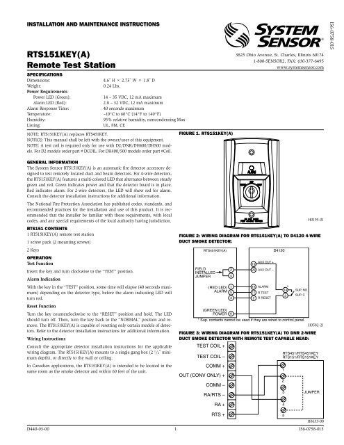
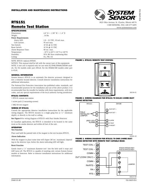
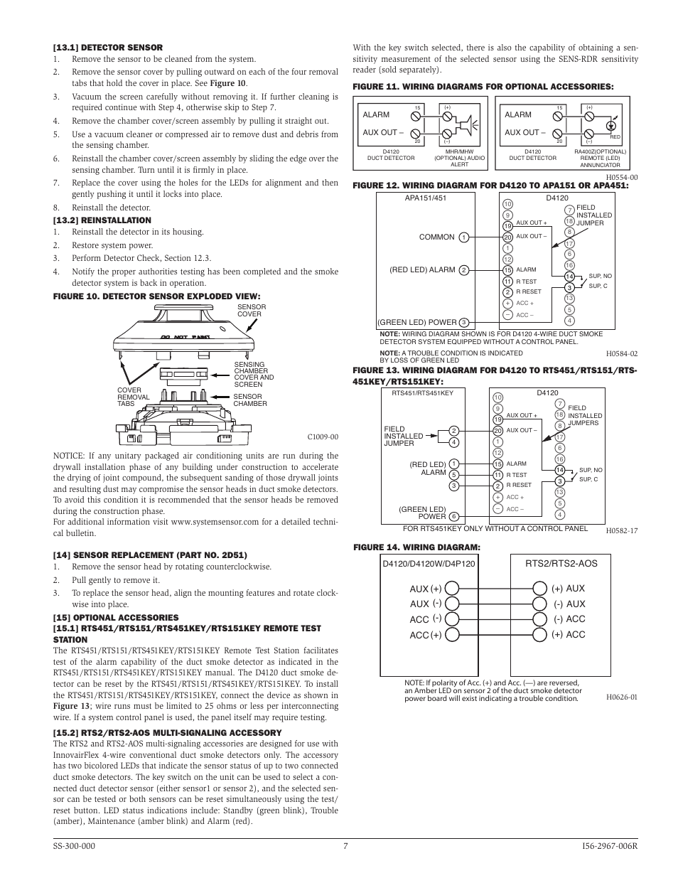
Here's how I usually wire in my smoke detectors on Rtus and commercial splits. Like,subscribe or comment below WIRING OF RTS151 Consult the appropriate detector installation instructions for the applicable wiring diagram. The RTS151 mounts to a single gang box (2 1/2” minimum depth), or directly to the wall or ceiling. See Figure 8 for wiring diagram of RTS151 with Duct Smoke Detectors.
Duct Smoke Detector Wiring Diagram Download. Assortment of duct smoke detector wiring diagram. A wiring diagram is a simplified traditional photographic depiction of an electric circuit. It reveals the elements of the circuit as streamlined shapes, and also the power and also signal connections between the devices. A wiring diagram typically gives details regarding the loved…

Duct smoke detector wiring diagram
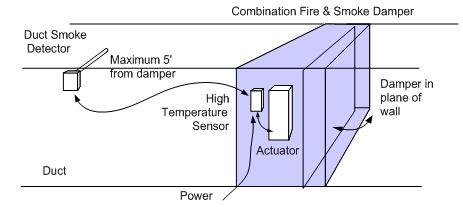
SuperDuct Four-Wire Duct Smoke Detector 1 SuperDuct Four-Wire Duct Smoke Detector P/N 3100685 • Rev 2.0 • 18AUG05 Combination smoke sensor and controller ... Figure 1: Duct smoke detector application diagram The controller is designed for multiple operating voltages and provides relay contacts for connection to fire alarm systems, Smoke introduced into an air duct system will be distributed throughout the entire building. Smoke detectors designed for use in air duct systems are used to sense the presence of smoke in the duct. Model D4120 and D4S Duct Smoke Detectors utilize 4-wire photoelectric technology for the detection of smoke. This detection method, when com- sensor head installation manual. Failure to comply with these requirements may prevent the detector from activating when smoke is present in the air duct.6 pages
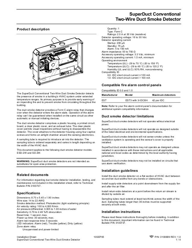
Duct smoke detector wiring diagram. Also verify HVAC shutdown and closure of (any) smoke doors. These functions must be done by the FACU, rather than by integral smoke detector relay contacts. Shutdown must occur within 20 seconds, except gas pack units can be arranged for up to 60 seconds delay before the fan stops, to prevent heat exchanger damage. Alarm Normal NORMAL ALARM Return air Remote Indicator Duct smoke detector FACP HVAC unit Duct smoke Supply air detector HVAC controls Remote Indicator DS-SD DS-SD FROM FACP SIGA-LED 1 3 2 4 7 8-+ TO NEXT DEVICE 1 3 2 4} 7 + SIGA-LED-Dimensions 8.70 x 5.45 x 1.90 in (220.98 x 138.43 x 48.26 mm) Wire size 14 to 22 AWG Smoke detection method ... The SL-2000 Series smoke detector is fitted with a mounting base that will accept an ionization smoke detector head model 55000-225APO or photoelectric smoke detector head model 55000-328APO. The duct unit supports two sets of form "C" alarm contacts, one form "A" alarm contact and one form "C" trouble contact. The Go ahead and enjoy some dirty incest kinky fun with desi aunty sex
Smoke introduced into this air duct system will be distributed throughout the entire building. Smoke detectors designed for use in air duct systems are used to sense the presence of smoke in the duct. Model D355PL Air Duct Smoke Detector utilizes photoelectric technology for the detection of smoke. This detection method, when combined with an ... 2. Jun 21, 2009 · 1969--SMOKE DETECTOR Randolph Smith and Kenneth House patent a battery-powered smoke detector for home use. Sep 27, 2021 · A smoke detector has to be versatile, which means that it will sound and show an alert as soon as there is a fire hazard in the property. The word comes from the Latin spirare, meaning to breathe. Duct Smoke Detector Wiring Diagram - Simple Wiring Diagram - 2 Wire Smoke Detector Wiring Diagram. Wiring diagram also gives useful suggestions for tasks which may demand some added gear. This book even contains recommendations for additional provides that you might require in order to end your projects. The SM-501 Series smoke detector is fitted with a mounting base that will . accept an ionization smoke detector head model 55000-225 (or 55000-250) or photoelectric smoke detector head model 55000-328 (or 55000-350). The duct unit supports two sets of form "C" alarm contacts and one form "C" trouble contact.
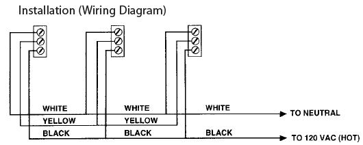
2.5.2019 · Smoke detector spacing with beams and smooth ceilings can be tricky. This article will walk you through the NFPA 72 requires for smoke detectors spacing based on the ceiling height and beam depths. Article also covers smoke spacing for corridors and rooms under 900 square feet. Tags: addressable duct smoke detector wiring diagram, d4120 duct smoke detector wiring diagram, duct smoke detector installation manual, duct smoke detector wiring diagram, hvac smoke detector wiring diagram, siemens duct smoke detector wiring diagram, siga-sd duct smoke detector wiring diagram, simplex duct smoke detector wiring diagram, sl ... Wiring Diagrams for Duct Smoke Detectors | Duct Detectors Smoke Detection NFPA 90A Code. Firstly, it is important to follow all the instructions provided with the new duct detector. Always follow duct detector manufacturer’s instructions and code for wiring. The wiring diagram graphics here are for illustration purposes only. Duct Smoke Detector Wiring Diagram | Manual E-Books – Duct Smoke Detector Wiring Diagram. In addition, Wiring Diagram provides you with time body during which the projects are to be completed. You’ll be in a position to understand specifically if the tasks ought to be completed, that makes it much easier for you to properly control your time and efforts. Wiring A Hvac Ducted Smoke Detector ...
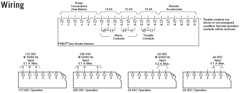
The following wiring diagrams are applicable only to compatible, current limited, UL Listed remote accessories from Air Products and Controls. Use of any other devices may result in damage to the duct smoke detector, potential injury, and will void any applicable warranties. á. REMARQUE:
Duct Smoke Detector Housing with Photoelectric Detector* Model Description Compatibility 4098-9685 2-Wire Duct Detector, standard operation No relay(s) Remote LED indicator and test stations per below 4098-9688 2-Wire Duct Detector with supervised single remote relay output; includes one 4098-9841 relay; NOTE: Must be only device on
22.4.2014 · Fire alarm requirements for group B occupancy based on the 2012 International Fire Code section 907. Sprinkler monitoring is required and a manual fire alarm system is required if the occupant load combined is over 500 persons. This includes manual pull …
RWF-N or RWJ-N 4 Wire Ionization Duct Smoke Detector RWF-P or RWJ-P 4 Wire Photoelectric Duct Smoke Detector DETECTOR HEAD MODEL NUMBER: Ionization Detector Head: 55000-225APO or 55000-250APO Photoelectric Detector Head: 55000-328APO or 55000-350APO POWER REQUIREMENTS: QUIESCENT CURRENT ALARM CURRENT 24VAC 50mA 24VAC 180mA 24VDC 13mA 24VDC 62mA
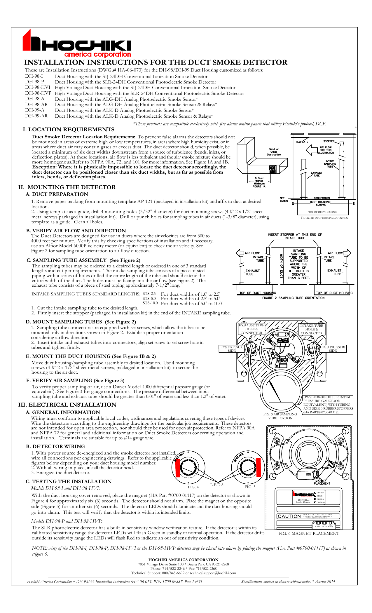
general and additional information on Duct Smoke Detectors concerning operation and installation. Terminals are suitable for up to #14 gauge wire. To verify proper sampling of air, use a Dwyer Model 4000 differential pressure gauge (or equivalent). See Figure 3 for gauge connections. The pressure differential between input sampling tube and exhaust tube should be greater than 0.01" of water ...
duct smoke detector wiring diagram - What's Wiring Diagram? A wiring diagram is a type of schematic which uses abstract pictorial symbols to show all of the interconnections of components inside a system.
System wiring diagram for 2-wire duct smoke detectors (powered from initiating device circuit): 24 VAC (+10%, –15%) FULLW AVE RECTIFIED, UNFIL TERED POWER MAY BE USED RTS451/RTS451KEY (OPTIONAL) REMOTE TEST S TATION MAGNET TEST SWITCH ALARM LED (RED) 4 5 2 1 (+) (–) + RA + RT S – RA + TEST COIL – TEST COIL + IN + OUT – (–) (+) D2 24 VDC AUX POWER SUPPLIED BY USER (100mA SUPPL Y ...
Hvac Duct Smoke Detector Wiring Diagram. Sl 2000 duct smoke detector hvac talk heating air refrigeration weatherproof ionisation universal voltage detectors wire detection nfpa 90a 4 low profile dn 60267 notifier and nx 8 edwards superduct conventional two. Firex 2650 761 Photoelectric 115 230 Vac Universal Voltage Duct Smoke Detectors.
Duct Smoke Detector Wiring Diagram. Variety of duct smoke detector wiring diagram. A wiring diagram is a simplified traditional pictorial depiction of an electric circuit. It shows the components of the circuit as streamlined shapes, as well as the power as well as signal links between the gadgets. A wiring diagram usually offers info concerning…
Smoke introduced into an air duct system will be distributed throughout the entire building. Smoke detectors designed for use in air duct systems are used to sense the presence of smoke in the duct. Model D4120A and D4SA Duct Smoke Detectors utilize 4-wire photoelectric technology for the detection of smoke. This detection method, when com-
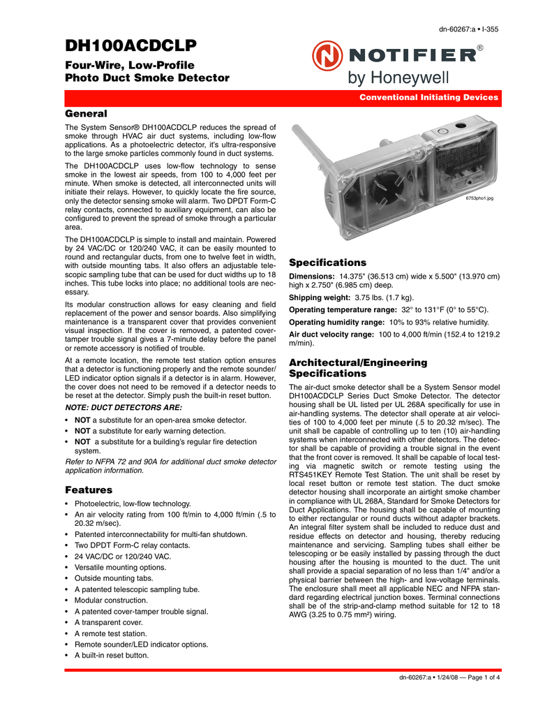
System wiring diagram for 4-wire duct smoke detectors Wiring diagram for DH100ACDCLP to SSK451: 15 19 14 3 20 1 3 Alarm Signal 2 Aux. Power + Sup. N. O. Sup. COM Aux. Power – NOTE: Wiring diagram shown is for DH100ACDCLP 4-wire duct smoke detector system equipped without a control panel. Alarm (Red LED) Power (Green LED) Common DH100ACDCLP APA451 NOTE: A trouble condition is indicated when ...
Smoke introduced into an air duct system will be distributed throughout the entire building. Smoke detectors designed for use in air duct systems are used to sense the presence of smoke in the duct. Model D4120 and D4S Duct Smoke Detectors utilize 4-wire photoelectric tech - nology for the detection of smoke. This detection method, when combined
with “R” Remote Test Capable Detector Head Option: DNR to RA100Z: System wiring diagram for DNR: RTS151/RTS151KEY JUMPER 4 5 3 2 1 TEST COIL + TEST COIL – COMM + OUT (CONV ONLY) + COMM – RA/RTS – RA+ RTS + Wiring for Intelligent Non-Relay Duct Smoke Detector COMM. LINE (+) UL/FM LISTED CONTROL DETECT PANEL 1ST OR IN LOOP 2ND DETECTOR ...
System wiring diagram for 4-wire duct smoke detectors Specifications Size 143⁄ 8″ (37 cm.) Length 51⁄ 2″ (14 cm.) Width 23⁄ 4″ (7 cm.) Depth Shipping Weight 33⁄ 4 lbs. (1.7 kg.) Operating Temperature Range 32° to 131°F (0° to 55°C) Storage Temperature Range –22° to +158°F (–30° to +70°C) Operating Humidity Range 10% to 93% relative humidity non-condensing Air Duct ...
additional information on Duct Smoke Detectors concerning operation and installation. Terminals are suitable for up to #14 gauge wire. B. DETECTOR WIRING.3 pages
any other devices may result in damage to the duct smoke detector, potential injury, and will void any applicable warranties. SL-2000 Series Duct Smoke Detectors * NOTE: For remote accessories with a Trouble LED (yellow), a jumper wire must be placed between Terminals 20 and 15. The Trouble LED wi ll
Smoke introduced into the air duct system will be distributed throughout the entire building. Smoke detectors designed for use in air duct systems are used to sense the presence of smoke in the duct. Model D2 Duct Smoke Detector utilizes photoelectric technology for the de-tection of smoke. This detection method, when combined with an efficient
The panel, in turn, depending on programming and wiring, turns off fans, blowers, and other devices. The duct housing allows for mounting of SK-RELAY addressable relay module. The Model SK-DUCT Air Duct Smoke Detector utilizes photoelectric technology for the detection of smoke. It provides early detection of smoke
NOTICE: This manual shall be left with the owner/user of this equipment. ... Model D4120 and D4S Duct Smoke Detectors utilize 4-wire photoelectric tech-.
E-PDD Duct Smoke Detector Installation Sheet Operation The duct smoke detector's primary purpose is to provide early warning of an impending fire and shut down the HVAC unit in order to prevent smoke from circulating throughout the building. The duct smoke detector is designed for use in duct
WARNING: Duct detectors have specific limitations. Duct detectors are not a substitute for an open area smoke detector. Duct detectors are not a substitute for early warning detection or a replacement for a building's regular fire detection system. Smoke detec-tors are not designed to detect toxic gases which can build up to hazardous levels in
c. Kitchen exhaust duct (1) A kitchen exhaust duct running outside a building shall not be located within 3m of any unprotected openings. This separation distance can be reduced to 1.5m if the unprotected opening is on the same plane as the duct. (See Diagram 7.1.13c.(1) - 1 and 2)
Wiring for 2-wire Duct Smoke Detector System wiring diagram for 2-wire duct smoke detectors powered from initiating device circuit. 24 V AC 10 15 FULL W AVE RECTIFIED UNFIL TERED. Pin On Electric . 15 19 14 3 20 1 3 Alarm Signal 2 Aux.
Duct Smoke Detector Location Requirements: To prevent false alarms the detectors should not ... DH-98-AR /DH-99-AR WIRING DIAGRAM DH-98-A/DH-99-A WIRING DIAGRAM The DH-98-A/DH-99-A and DH-98-AR/DH-99-AR are not self-contained sensors. This product is compatible only with fire alarm
The jet fan system, such as the mechanised air supply fans, smoke exhaust fans, jet fans, duct works and wiring shall be capable of operating effectively at 250°C for 2 hours. The fans, ducts and wiring shall be tested in accordance with BS 7346: Pt 2, BS 476: Pt 24 and SS 299 respectively.
Wiring for 2-wire Duct Smoke Detector System wiring diagram for 2-wire duct smoke detectors (powered from initiating device circuit): Electrical Ratings Power supply voltage: 8.5-35VDC Input capacitance: 0.1 µF max. Reset voltage: 2 (-) - (-) (+) (-) -
sensor head installation manual. Failure to comply with these requirements may prevent the detector from activating when smoke is present in the air duct.6 pages
Smoke introduced into an air duct system will be distributed throughout the entire building. Smoke detectors designed for use in air duct systems are used to sense the presence of smoke in the duct. Model D4120 and D4S Duct Smoke Detectors utilize 4-wire photoelectric technology for the detection of smoke. This detection method, when com-
SuperDuct Four-Wire Duct Smoke Detector 1 SuperDuct Four-Wire Duct Smoke Detector P/N 3100685 • Rev 2.0 • 18AUG05 Combination smoke sensor and controller ... Figure 1: Duct smoke detector application diagram The controller is designed for multiple operating voltages and provides relay contacts for connection to fire alarm systems,









0 Response to "35 duct smoke detector wiring diagram"
Post a Comment