35 in a state transition diagram, the circle to the left is the final state.
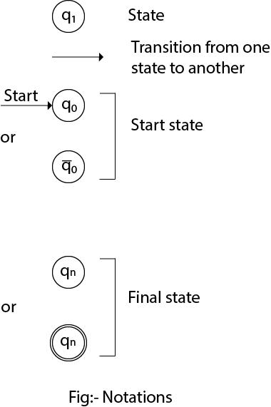
1. Transition diagrams Each state is a node Then the transition diagram has an arc from q to p, labeled a There is an arrow to the start state q0 Nodes corresponding to final states are marked with doubled circle 2. Transition tables Tabular representation of a function The rows correspond to the states and the columns to the inputs In a state transition diagram, the circle at the right with a hollow border is the initial state. False.
Accepting states or final states are indicating by a double circle. Some Notations that are used in the transition diagram: There is a description of how a DFA operates: 1. In DFA, the input to the automata can be any string. Now, put a pointer to the start state q and read the input string w from left to right and move the pointer according to ...
In a state transition diagram, the circle to the left is the final state.
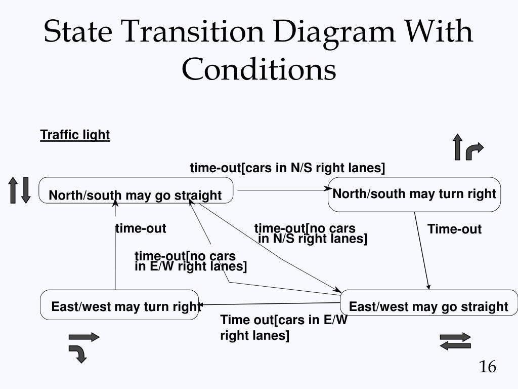
In a state transition diagram, the circle at the right with a hollow border is the initial state. True False. False. In a state transition diagram, the circle at the right with a hollow border is the initial state. False. In a state transition diagram, the circle to the left is the final state. False. In a state transition diagram, the states appear as rounded rectangles with the state names inside. Transaction States in DBMS. States through which a transaction goes during its lifetime. These are the states which tell about the current state of the Transaction and also tell how we will further do the processing in the transactions. These states govern the rules which decide the fate of the transaction whether it will commit or abort.
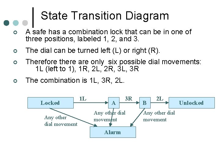
In a state transition diagram, the circle to the left is the final state.. 4, State transition diagram, A tool used to depict the sequence and variation of ... The circle at the right with a hollow border is the final state. Transcribed image text: The figure below shows the state transition diagram of a finite state machine (FSM). This diagram shows the input conditions which initiate the transition. If no input condition is satisfied, then the FSM remains in the same state. a 1 start st task1 tl FSM termin task2 clock The outputs are defined in the following Table: state start st taskl ask2 ermin ul Implement ... In a state transition diagram, the circle to the left is the final state. F23.A class diagram resembles a horizontal flowchart that shows the actions and ... State Transition Testing is a black box testing technique in which changes made in input conditions cause state changes or output changes in the Application under Test(AUT). State transition testing helps to analyze behaviour of an application for different input conditions. Testers can provide positive and negative input test values and record the system behavior.
Solution. Taking as states the digits 0 and 1 we identify the following Markov chain (by specifying states and transition probabilities): 0 1 0 q p 1 p q where p+q= 1. Thus, the transition matrix is as follows: P = q p p q = 1−p p p 1 −p = q 1−q 1 −q q . It is clear that the probability that that the machine will produce 0 if it starts ... In a state transition diagram, the states appear as rounded rectangles with ... In a state transition diagram, the circle to the left is the final state.26 Nov 2012 · Uploaded by Derek Banas t is the state at timet. On the transition diagram, X t corresponds to which box we are in at stept. In the Gambler’s Ruin (Section 2.7), X t is the amount of money the gambler possesses after toss t. In the model for gene spread (Section 3.7), X UML state diagram. There are a total of two states, and the first state indicates that the OTP has to be entered first. After that, OTP is checked in the decision box, if it is correct, then only state transition will occur, and the user will be validated.
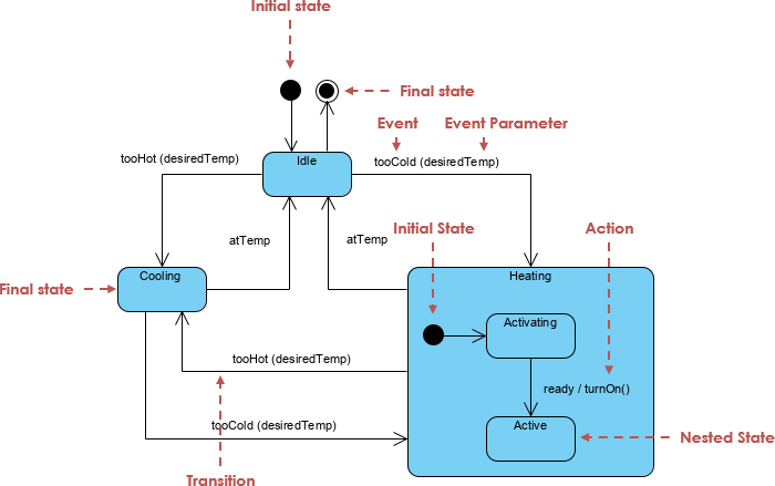
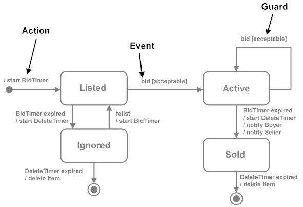
An initial state, also called a creation state, is the one that an object is in when it is first created, whereas a final state is one in which no transitions ... In a state transition diagram, the circle to the left is the final state. diagram. A use case ____ is a visual summary of several related use cases within a ... Initial and Final States. The initial state of a state machine diagram, known as an initial pseudo-state, is indicated with a solid circle. A transition from ... The syntax and conventions used in state machine diagrams will be discussed in full in the following sections. States. A state is denoted by a round-cornered rectangle with the name of the state written inside it. Initial and Final States. The initial state is denoted by a filled black circle and may be labeled with a name.
Ppt State Transition Diagrams Powerpoint Presentation Free Download Id 1715920
Transaction States in DBMS. States through which a transaction goes during its lifetime. These are the states which tell about the current state of the Transaction and also tell how we will further do the processing in the transactions. These states govern the rules which decide the fate of the transaction whether it will commit or abort.

Figure 3 Simplification Of State Transition Diagrams In Average Unavailability Analysis By Using Generalized Perturbation Theory
In a state transition diagram, the circle at the right with a hollow border is the initial state. False. In a state transition diagram, the circle to the left is the final state. False. In a state transition diagram, the states appear as rounded rectangles with the state names inside.

Technical To Decide Whether Stream Of 0 And 1 Is Divisible By 3 Or Not
In a state transition diagram, the circle at the right with a hollow border is the initial state. True False. False.

State Machine Diagram Uml 2 Tutorial Sparx Systems
Finite State Machine Wikipedia

Uml State Diagrams With Draw Io Draw Io
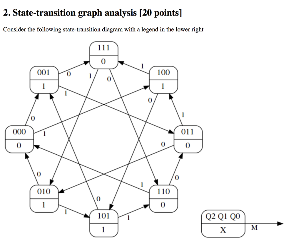
Solved 2 State Transition Graph Analysis 20 Points Chegg Com

State Machine Diagram Uml 2 Tutorial Sparx Systems

Building A State Machine Fab Slider
Transition Diagram Javatpoint
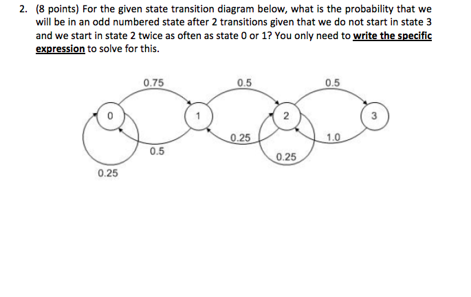
Solved 2 8 Points For The Given State Transition Diagram Chegg Com
State Transition Matrix And Diagram

Fun With Arduino 17 Railway Crossing State Transition Diagram Switch Case Fun With Arduino
1

Uml State Diagrams With Draw Io Draw Io

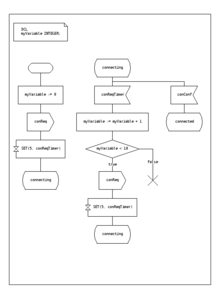
Configuring A Process R2 Docuo Documentation
Class
All You Need To Know About State Diagrams

Uml State Machine Wikipedia

Architecture Left And State Transition Diagram Right Of Download Scientific Diagram

Figure 1 Derivation Of Line Shape Function In The Optical Conductivity By A New Diagram Method

Modeling A Uml State Diagram Support Bizzdesign Support

State Machine Diagram Vs Activity Diagram

State Transition Diagram For Searching For A Door First The Door Edge Download Scientific Diagram
State Transition Representation In State Diagram

Uml 2 State Machine Diagrams An Agile Introduction
Se 325425 Principles And Practices Of Software Engineering

State Machine Diagram Uml 2 Tutorial Sparx Systems

Transition Maps Guide Successful Asynchronous State Machine Design Edn
State Transition Diagrams Stickyminds

Teaching Innovation Entrepreneurial Global Ppt Download
State Diagram Comprehensive Guide With Examples By Warren Lynch Medium

State Machine Diagram Uml 2 Tutorial Sparx Systems

Uml State Diagrams With Draw Io Draw Io
What Is State Machine Diagram
0 Response to "35 in a state transition diagram, the circle to the left is the final state."
Post a Comment