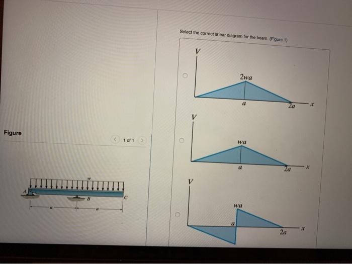
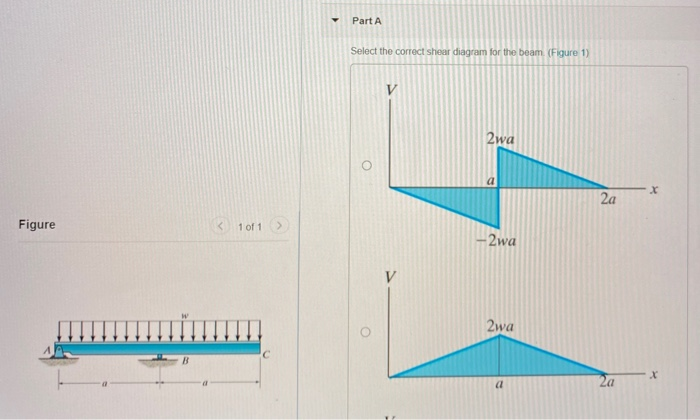
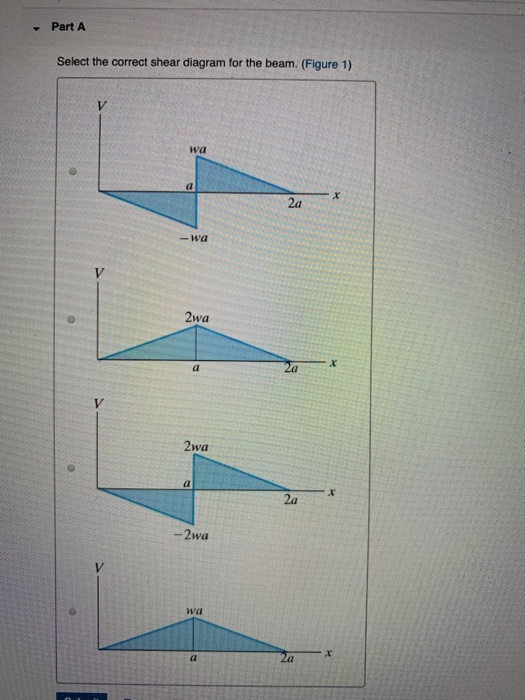
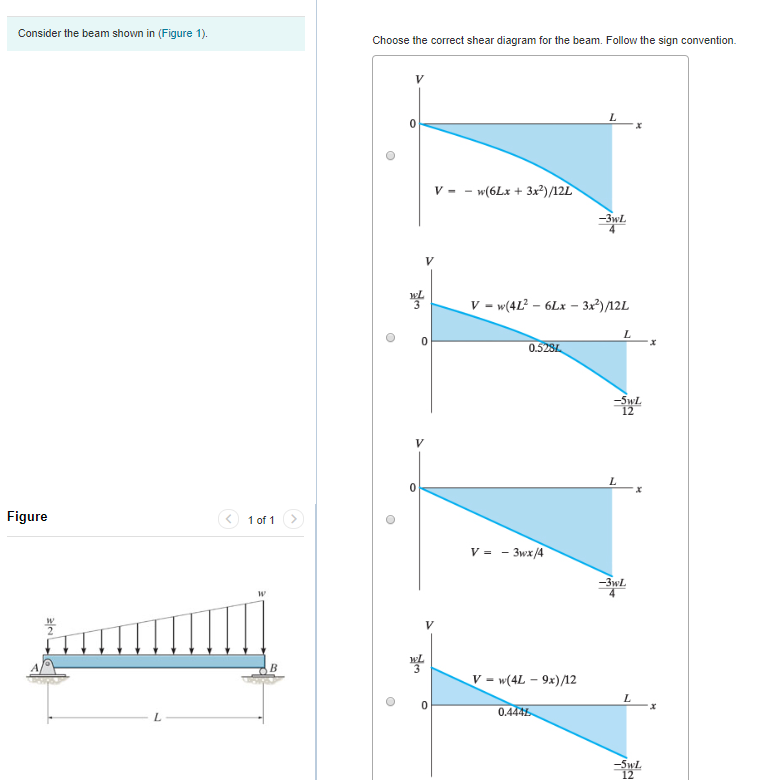
36 select the correct shear diagram for the beam. (figure 1)
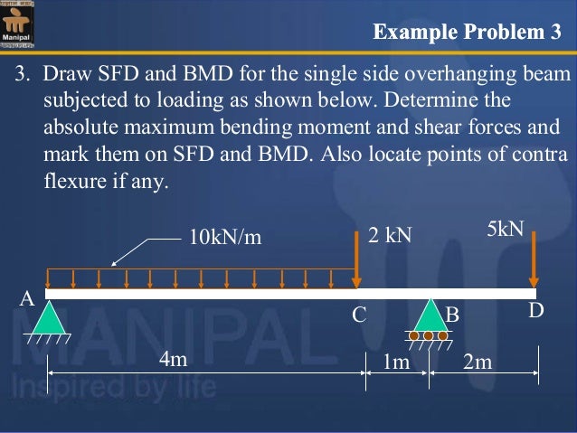
The curvature of a beam is identified as dθ /ds = 1/R In the figure δθ is small and δ x; is practically = δ s; i.e ds /dx =1. From this simple approximation the following relationships are derived. Integrating between selected limits. The deflection between limits is obtained by further integration. RB = -1 kN. (For member BC). So SFD will be. So For member AC, SF will be. For section AP, ...1 answer · Top answer: "Explanation ∑ V = 0 ⇒ RA + RB = 5 kN HB = 3 kN. ∑ MB = 0 ⇒ RA × 15 – 3 × 5 – 5 × 15 = 0 ⇒ 15 RA = 90 ⇒ RA = 6 kN. RB = -1 kN. ...
0. For convenience, formulas are derived and spreader beam design calculation xls free download 3: An update to the Beam Calculator tool. Over the midspan, L/4 x 3L/4, the bending moment is constant, the shear force is zero, the beam is in pure bending. Download Forms ATTAR. M) 1) Design a cantilever beam of span 3m subjected to u.
Select the correct shear diagram for the beam. (figure 1)
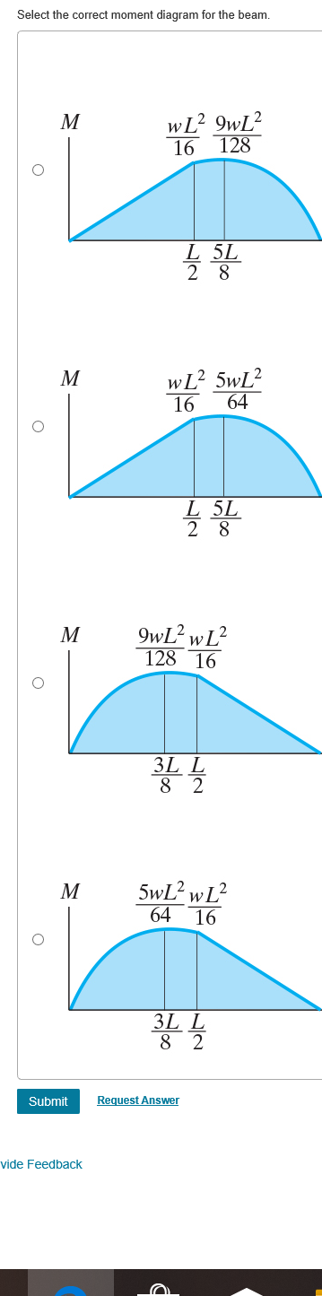
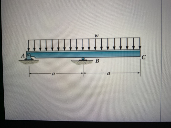
Dec 31, 2020 · Example 1: internal actions at a section cut of a simply supported beam. For the following simply supported beam, loaded by a uniform distributed load: Find the bending moment and the transverse shear force at the middle span; Find the bending moment and the transverse shear force as a function of distance x from edge A; Support reactions Mar 5, 2021 — Fig. 4.1. Internal forces in a beam. 4.2 Basic Definitions. 4.2.1 Normal ... The bending moment diagram of the beam is shown in Figure 4.5d. (Figure 1) wa 2a -wa 2wa 2wa x. 2a -2wa wa -Part B Select the correct moment diagram for the beam. 2a 2a 2a 24. This problem has been solved ...
Select the correct shear diagram for the beam. (figure 1). Sep 21, 2021 · Detailing Beams of Special Moment Frames per ACI 318M-19 – Part 2: Calculating the Probable Shear Detailing Beams of Special Moment Frames per ACI 318M-19 – Part 1: Ensuring Correct Geometrical Proportions and Adequate Flexural Reinforcement Problem 7.56 4 of 4 Part A Draw the shear diagram for the beam. Follow the sign convention. (Figure 1) Click on "add vertical line off" to add discontinuity ...1 answer · 0 votes: We were unable to transcribe this image Ә) 2 х = 0 By - 40.5 gas my 4* * * и оп5 - 0, 5x x 0.5%, 4 • 0, це 10 2 3. Ке? О Maxime B., M 2 ... Figure 6a shows a footing loaded at the center. From a rigid wide beam analogy, P = R x L. Similarly, for an eccentrically loaded footing, the reaction will vary linearly from one end to the other as shown in Figure 6c. Equations 3 and 4 can be solved to find end reactions. But none of the equations contain modulus of subgrade reaction (Ks). Problem 1: Computation of Reactions. Find the reactions at the supports for a simple beam as shown in the diagram. Weight of the beam is negligible. Figure:.25 pages
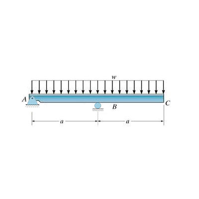
Figure 5.2.1. Table of common two-dimensional supports and their representation on free body diagrams. Three-dimensional Reactions. The main added complexity with three-dimensional objects is that there are more possible ways the the object can move, and also more possible ways to restrain it. Answer to: Select the correct shear diagram for the beam. (Figure 1) By signing up, you'll get thousands of step-by-step solutions to your homework...1 answer · Top answer: Let the reaction at point A and point B is Ra and Rb respectively. Taking moment about point A, (w×2a)×a=Rb×a(w×2a)×a=Rb×a {eq}R_b... Mar 8, 2021 — Nov 16,2021 - A loaded beam is shown in the figure. The bending moment diagram of the beam is best represented asa) b) c) d) Correct answer ... Draw the moment diagram for the beam for the figure below. View Answer Two 0.0024 kg point charges on 1.0 m long threads repel each other after being equally charged.
(Figure 1) wa 2a -wa 2wa 2wa x. 2a -2wa wa -Part B Select the correct moment diagram for the beam. 2a 2a 2a 24. This problem has been solved ... Mar 5, 2021 — Fig. 4.1. Internal forces in a beam. 4.2 Basic Definitions. 4.2.1 Normal ... The bending moment diagram of the beam is shown in Figure 4.5d. Dec 31, 2020 · Example 1: internal actions at a section cut of a simply supported beam. For the following simply supported beam, loaded by a uniform distributed load: Find the bending moment and the transverse shear force at the middle span; Find the bending moment and the transverse shear force as a function of distance x from edge A; Support reactions


0 Response to "36 select the correct shear diagram for the beam. (figure 1)"
Post a Comment