37 control transformer wiring diagram
Apr 20, 2017 — 1 See Page V7-T7-11 for wiring diagrams. 2 105°C insulation system. 3 Secondary fuse clips are not available on this catalog number.27 pages A wiring diagram is a simple visual representation of the physical connections and physical layout of an electrical system or circuit. It shows how the electrical wires are interconnected and can also show where fixtures and components may be connected to the system.
[SOLVED] Add open wire to the common wire going to the Condenser unit. After writing that out, complete face palm cause that makes so much sense lol, thank you everyone for your help! So I’m installing a Nest thermostat that needs a common wire. My furnace only has 4 wire outputs, but fortunately the wire to the thermostat does have an open C-wire (just not connected to anything). I’ve ordered a 24v transformer that is meant to plug into an AC outlet by the thermostat where one wire connects t...
Control transformer wiring diagram
A wiring diagram is an electrical print that shows connections of all components in a piece of equipment.A schematic diagram is a type of drawing that illustrates the electrical connections and functions of specific circuit arrangements with graphic symbols.A ladder diagram is a diagram that explains the logic of the electrical circuit or system using standard NEMA or IEC symbols. ​ https://preview.redd.it/1hbv41sv0vy71.jpg?width=2000&format=pjpg&auto=webp&s=1eb52ff170638a99c80f954d4d7a00f74f9dc569 Search is a vital aspect of app usability. When application developers add a great search experience to their maps, they earn user appreciation. In a previous article, we showed [how to create a simple app to display TomTom Maps on a React Native WebView control](https://developer.tomtom.com/blog/build-different/using-tomtom-maps-web-sdk-react-native-w... So I had a reme halo led installed, but I noticed it was on whether the system was on or off. I know the old halo was supposed to be wired this way to preserve bulb life, but the led is not (and it technically voids my warranty). I was looking to fix it myself. Intuitively, I would think to connect it between the green and common outputs of the control board. That way it cuts on when the fan does and uses the existing 24v from the control panel. But the wiring diagram from reme uses a relay....
Control transformer wiring diagram. CONNECTION DIAGRAMS. CONNECTION DIAGRAM: CONNECTION DIAGRAM: CONNECTION DIAGRAM: GROUP "A". GROUP "B". GROUP "C". CONNECTION DIAGRAM: CONNECTION DIAGRAM:.1 page Consider the above 2-way switch wiring diagram which has been used to control a bulb in staircase. The schematic shows that circuit is completed and bulb is ON. Suppose you want to OFF the bulb from the upper switch at top of stair ( (upper portion of staircase) ) simply Switch OFF the switch then circuit will break and the bulb will be OFF. I've done a lot of searching around and found some into that leads me to believe I'm doing the right thing with this setup. I have an oil furnace, 2 Taco controllers (ZVC404 & ZVC406) and 4 air condensers/air handlers. The 4 zones with their own separate AC systems are using Nest 4th Gen's w/o a C wire, no problems. The 5 zones that are heat only are 2-wire only (no C wire) back to the Taco controllers that I intend to use Nest E's for. The problem is I know running 5 Nest E's may draw m... Hi all, Hoping to get some feedback on V2 of my generator control board. It is to make an old Generac standby generator smart (well... mostly its for fun, but also that). V1 I've already had printed and assembled, found a few flaws (well, mostly just some things I wanted to add, as well as some logic around relay5 being wrong) and had to add some mounting holes. Project is intended to be controlled by ESPHome. Heavily rearranged the PCB to keep it oriented visually how it'll be mounted (easier ...
Hey all, we have two HVAC units in this 1927 arts and crafts house, one in the attic and one in the basement. Both were relatively recent additions, house used to have hot water heat up until around 10 years ago or so. The house was formerly owned and lived in by a reknowned slumlord who later rented it out. He sold it to help cover legal expenses, so that's the background of the house here. I went to inspect the blower fan and motor, and found the controller board was mounted in front of i... Wiring Diagram Book A1 15 B1 B2 16 18 B3 A2 B1 B3 15 Supply voltage 16 18 L M H 2 Levels B2 L1 F U 1 460 V F U 2 L2 L3 GND H1 H3 H2 H4 F U 3 X1A F U 4 F U 5 X2A R Power On Optional X1 X2115 V 230 V H1 H3 H2 H4 Optional Connection Electrostatically Shielded Transformer F U 6 OFF ON M L1 L2 1 2 STOP OL M START 3 START START FIBER OPTIC ... My furnace has been short cycling so I've been trying to figure out if everything is connected properly. I first added a C wire directly to the air handler/Furnace control board, but it still seems to shut off multiple times before hitting the target temperature. Since then I've been reading more about the the wiring and therefore traced all the wires in my Hvac system and came up with the diagram attached. It seems that I only have 1 transformer but the R wire directly from the furnace is bein... Three Phase Motor Connection Schematic, Power and Control Wiring Installation Diagrams. Star-Delta (Y-Δ) 3-phase Motor Starting Method by Automatic star-delta starter with Timer.
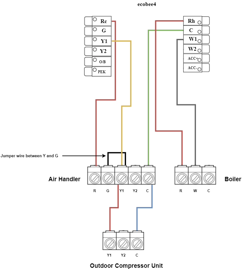
How many times have you heard people say of a sniper or a master swordsman, “They were born for that weapon!” Not every day, maybe, but you hear it. And what do they say about me? “What is that idiot doing?” “It’s a crazy man!” “He’s gonna get us all killed!” Well, I’m about to show them. It all started ten years ago, on a summer evening just after I had finished college. I was on my way home from meeting friends for a few beers and decided to take my old high school shortcut through a narro... Effectively speaking, I want to have a Solid State Relay (rated at 240v 50A) setup to interrupt a 240V line I have coming out of my electrical panel. Opening/Closing of the Relay will be done via the GPIO pins of the control board (Probably a Raspberry Pi). I also will want to have a simple 240v > 5V step down power supply in there, to power the RPI off that same 240V power (draw only a few milliamps) ~~Solid State Relay I am using:~~ https://www.amazon.ca/gp/product/B00DDDFUZG?psc=1 Scra... I just moved into a much larger house. At my old house, my ecobee4 controlled the forced-air furnace (which supplied a C wire); so I brought that thermostat with me, since I want wifi/homekit control. But the new house has a dual-zone (1st and 2nd floors separated) boiler for baseboard hot water radiators, and additionally a 2nd floor-only air conditioning system, for 3 thermostats in all. I'd like to consolidate the 2nd floor heating thermostat with the A/C thermostat, and use the ecobee for b... Charles Trout · 2010 · Technology & Engineering... control center, 66 H High and low-voltage connection split-phase motor, ... on motor nameplate, 20 Integral control transformer, wiring diagram for, ...
Installing Your Ecobee With A Boiler And Ac Dual Transformer System
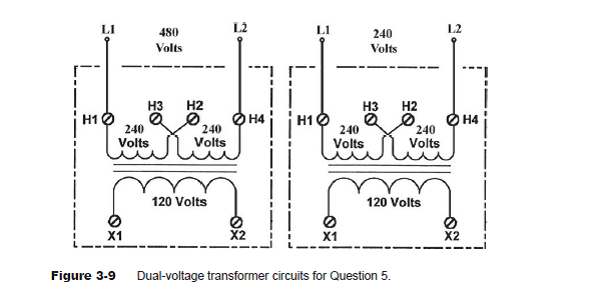
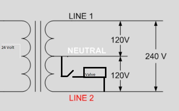
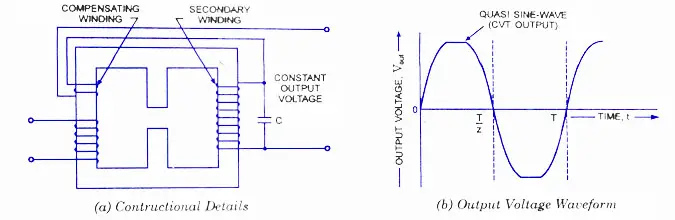
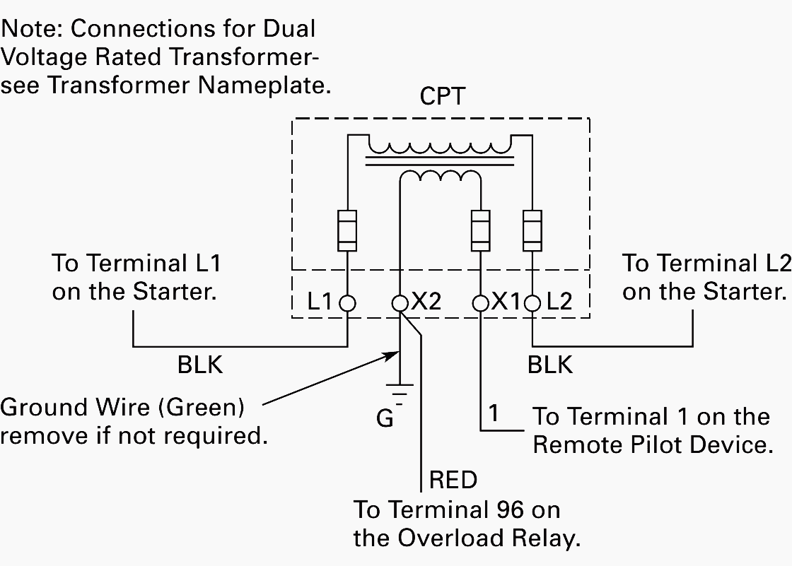
Oct 28, 2016 — A typical control transformer is shown in Figure 1 below. It consists of two separate coils of wire (windings) placed adjacent to each other ...
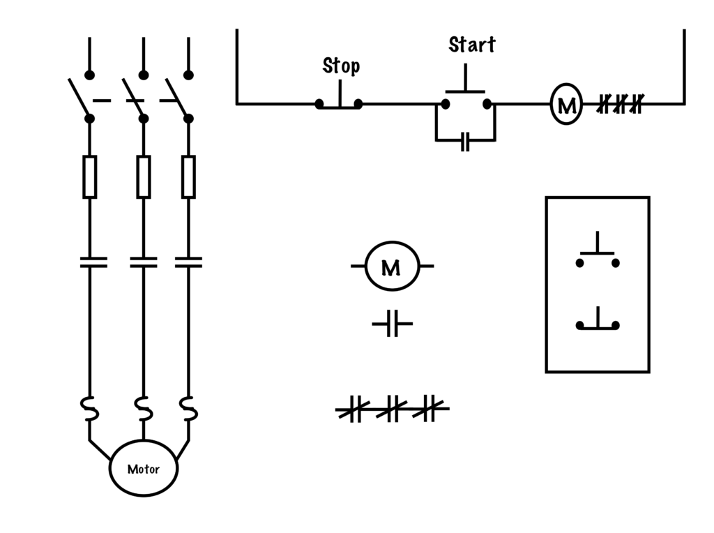
Transferring From Schematic To Wiring Diagram For Connection Purposes Basic Motor Control
Hey all. I had a question about circuit wiring. I guess this is a theory thing and I'm still a student/trainee not working in the field yet so no journeyman I could ask and it's midnight so I can't reach my Professor. Anyways, my professor talked about this a few months ago and he was talking about a time where he had an electrical engineer apply to teach under him. My professor has actual previous experience working as an electrician and the engineer never did, so he asked the engineer some bas...
Correctly Connect The Dual Voltage Control Transformer Cir Chegg Com
The control transformer line is particularly ... Single Phase Transformers ... 95 (3.75). 111 (4.375). 3.6 (7.9). 2. WEigHt kg (lbs). Wiring. DiAgrAm ...2 pages

Buck Boost Transformer
I'm thinking about making the switch from a substation to hydropower engineer. This will put me closer to the power generation side of power engineering which I'm more interested in, plus there are a lot of rivers and dams where I live. If you are an electrical hydropower engineer, I want to hear what you do. Background: I'm an electrical engineer. I have worked on the P&C (protection and controls) side, involving relaying (think SEL-351, 487, 311, 411, 451, RTACs, satellite clocks, fiber p...

Control Transformer An Overview Sciencedirect Topics
[First](https://www.reddit.com/r/HFY/comments/geph88/meet_the_freak_1/) | [Prev](https://www.reddit.com/r/HFY/comments/jmteq0/meet_the_freak_18/) | [Next](https://www.reddit.com/r/HFY/comments/k3zubv/meet_the_freak_20/) [Discord](https://discord.gg/ZVgVe5m) | [Patreon](https://www.patreon.com/ThisHasNotGoneWell) --- As I relaxed, my breathing and heart rate slowed, and I let it all give way to silence. I'd lived most of my life in the city, and as was the case for most city dwellers, it was...
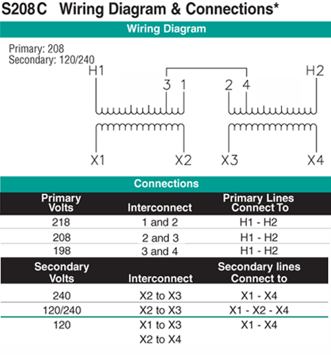
100 Kva Transformer Primary 208 Secondary 120 240 Jefferson 421 7242 000
Hello, I have a very old furnace (original to a 1950s home). No A/C. I installed a Nest thermostat (basic no touch screen, just tap the right side). The wiring to the thermostat is only 2 wires: RED and WHITE. The wiring worked fine and the thermostat operated the furnace without any problems, but the thermostat complained it was not getting enough power given there was no "C" (common) wire. Google offered to send me the power connector to help with this issue. I went to install the power...
Motor Power Control Wiring Diagram Edrawmax Editable Templates
In control panel wiring, it is customary to route AC power wires in such a way that they do not lay parallel to low-level signal wires, so that both forms of coupling may be reduced. If conductors carrying incompatible signals must cross paths, it is advisable to orient the conductors perpendicular to each other rather than parallel, like this:

Cosmostat Servo Voltage Stabilizer Isolation Transformer Wiring Diagram For Cosmostat Digital Servo Stabilizer Controller Single Display Module Servostabilizer In Electricalsolutions Controller Microcontrollers Servostabilizer
Typical Wiring Diagrams For Push Button Control Stations 3 Genera/ Information @ Each circuit is illustrated with a control circuit (continued) schematic or line diagram and a control station wiring diagram. l The schematic or line diagram includes all the components of the control circuit and indicates their function.

Pin On Wiring Diagram Templates Examples Edrawmax
> Who are you? > **Explorers, in the further regions of experience. Demons to some, angels to others.** --- The Cenobites are a clan of beings from another dimension, worshippers of a religion based around both suffering and pleasure. Summoned to Earth with a simple puzzle box, their role is to drag those who wish to experience all that existence can offer back to Hell. Whether they kill people on Earth or drag their bodies into the Labyrinth, the Cenobites will never relent in claimi...
1
HPS Imperator Wiring Schematics . ... Can a Control Transformer regulate the output voltage? ... Refer to page 52 for wiring schematic drawing.34 pages

Pin On Motor
I have a hot water baseboard system with a Taco SR503-4 controlling three pumps and a boiler. I am changing the thermostat on one of the heat-only zones from a battery powered 2-wire thermostat to an ecobee 3 lite. I've ran a new 18/7 wire from the thermostat to the Taco unit, so that I have plenty of leads to work with. I attached the the Taco's 24v common and that did not power the ecobee. Found this [support page](https://support.ecobee.com/hc/en-us/articles/236335908-Taco-SR503-4-Three-Z...
Practical Machinist Largest Manufacturing Technology Forum On The Web
0.How do you all memorize in situations that require word per word memorization for school? For example things like, 1.Memorizing the Bill of Rights 2.Lines for a school play 3.I'm considering law school. Anyone else attorneys? How did you go through memorizing the law for your classes? My original post ends here. The below is if you feel compelled for further discourse.. After seeing so many people reply in a short time frame to the above questions, I thought I'd ask a "few" more questions...
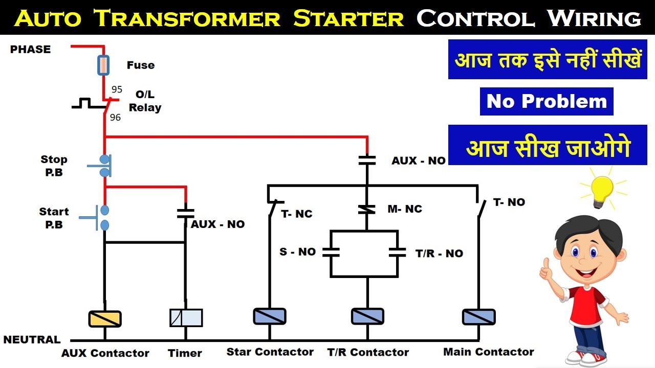
Auto Transformer Starter Control Wiring Auto Transformer Starter Connection Electrical Technician Youtube
The HPS IMPERATORTM series of machine tool industrial molded control transformers are available in many standard offerings. This wiring hook-up instruction ...9 pages
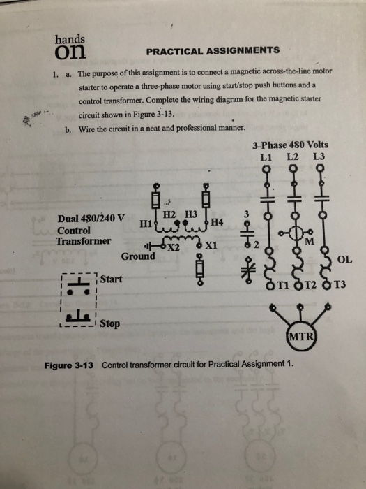
Solved Hands On 1 A The Purpose Of This Assignment Is To Chegg Com
Machine Tool and Control Power. Description. Type IP transformers are core and coil units designed for machine ... 1See page 14-6 for wiring diagrams.14 pages
Cvt Constant Voltage Transformer Working Circuit Diagram Application
So I had a reme halo led installed, but I noticed it was on whether the system was on or off. I know the old halo was supposed to be wired this way to preserve bulb life, but the led is not (and it technically voids my warranty). I was looking to fix it myself. Intuitively, I would think to connect it between the green and common outputs of the control board. That way it cuts on when the fan does and uses the existing 24v from the control panel. But the wiring diagram from reme uses a relay....

Wiring Diagram Of Three Phase Magnetically Controlled Controllable Reactor Download Scientific Diagram
​ https://preview.redd.it/1hbv41sv0vy71.jpg?width=2000&format=pjpg&auto=webp&s=1eb52ff170638a99c80f954d4d7a00f74f9dc569 Search is a vital aspect of app usability. When application developers add a great search experience to their maps, they earn user appreciation. In a previous article, we showed [how to create a simple app to display TomTom Maps on a React Native WebView control](https://developer.tomtom.com/blog/build-different/using-tomtom-maps-web-sdk-react-native-w...

Using Potential Transformers Continental Control Systems Llc
A wiring diagram is an electrical print that shows connections of all components in a piece of equipment.A schematic diagram is a type of drawing that illustrates the electrical connections and functions of specific circuit arrangements with graphic symbols.A ladder diagram is a diagram that explains the logic of the electrical circuit or system using standard NEMA or IEC symbols.

Buck Boost Transformer
Mastering Motor Control Center Mcc Wiring Diagrams And Equipment From Zero To Hero Eep
Transformer Diagram High Resolution Stock Photography And Images Alamy

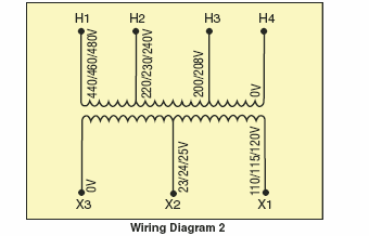
How To Wire A Multi Tap Transformer Functional Devices Inc

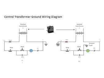
Motor Control Transformer Wiring Elec Eng World

480v Single Phase Transformer Wiring Diagram Diagram Base 480 Volt Motor Wiring Diagram
Electrification Us Abb Com
Control Transformers Power Transformers Voltage Transformers Stepdown Voltage Converters
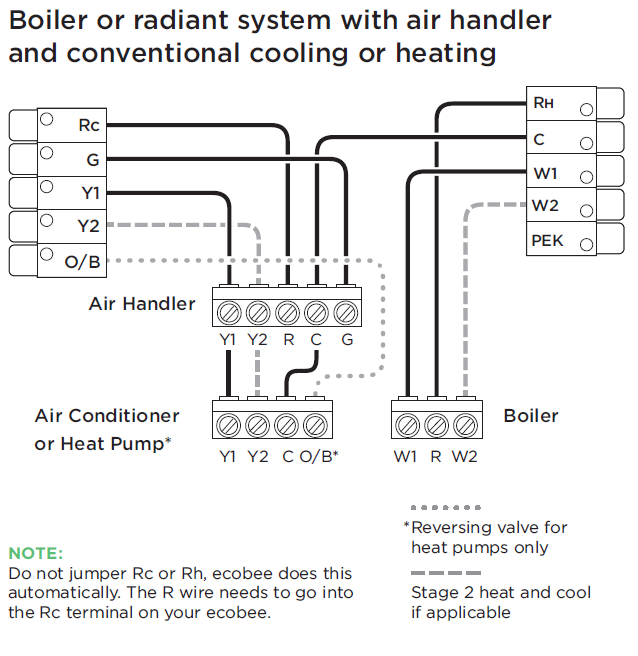
Installing Your Ecobee With A Boiler And Ac Dual Transformer System

Auto Transformer
Wiring Of Control Power Transformer For Motor Control Circuits Eep
Eaton Com
Galco Com

Overcurrent Protection Grounding And Applications For Control Transformers Technical Articles
Galco Com
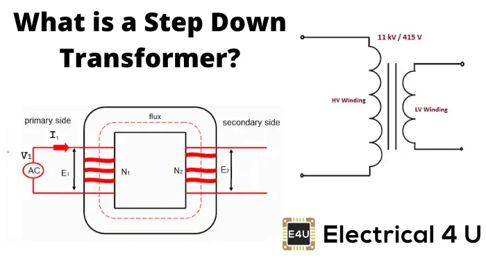
Step Down Transformer Definition Diagram Working Principle Electrical4u

Industrial Control Transformer Wiring Diagrams Pdf Document
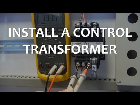
Install A Control Transformer Youtube
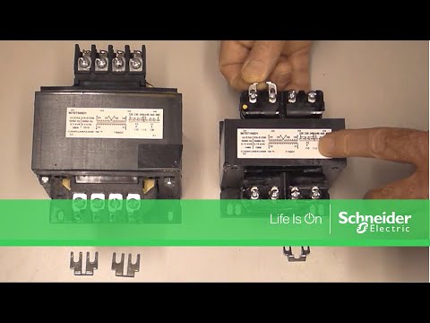
Installing Jumpers On Square D 9070 Industrial Control Transformers Schneider Electric Support Youtube
1
0 Response to "37 control transformer wiring diagram"
Post a Comment