37 intermatic t103 wiring diagram
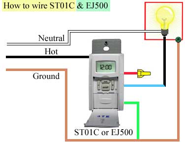
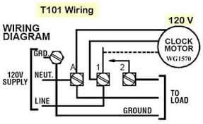
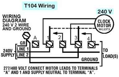
Intermatic T103 Wiring Diagram – wiring diagram is a simplified conventional pictorial representation of an electrical circuit. It shows the components of the circuit as simplified shapes, and the faculty and signal friends between the devices. A wiring diagram usually gives counsel practically the relative outlook and concurrence of devices ... T103 Timer Wiring Diagram. WIRING INSTRUCTIONS: To wire switch follow diagram above. Use solid or stranded COPPER only wire with insulation to suit installation. See gauge selection. I purchased an Intermatic T timer switch and am unable to get the clock running. This is a wiring diagram for the T is this how you have it wired?.
Dimension: 1500 x 1281. DOWNLOAD. Wiring Diagram Images Detail: Name: intermatic t103 wiring diagram – Intermatic cell Wiring Diagram Best 06 Intermatic Et1125 Intermaticring Diagram Timer T101 T103. File Type: JPG. Source: irelandnews.co. Size: 677.49 KB. Dimension: 1280 x 1641. DOWNLOAD.
Intermatic t103 wiring diagram
Intermatic Dial Timer Mechanism For Use With Grainger Items 2e022 4e024 T103 T103p Timers 4a213 T103m. Intermatic t101 timer wiring diagram t103 jpg trouble free pool landscape light two hot wires t104 off state full hooking up pump to relay switch parts dial mechanism for doentation time switches i bought an and wire it model t101m mechanical t7801b manualzz t106r 24 hour dt101 manual pdf ... Intermatic T103 Wiring Diagram Download. intermatic t103 wiring diagram - Building electrical wiring representations reveal the approximate areas as well as affiliations of receptacles, lights, as well as permanent electrical solutions in a building. Interconnecting wire paths may be revealed about, where specific receptacles or components should be on a common circuit. 07.09.2018 07.09.2018 6 Comments on Intermatic T103 Wiring How to wire Intermatic T and T timers - Hardware & Accessories, Tip, How -To and Do It Yourself Directions. Electrical - AC & DC - Intermatic T Timer Wiring - I had bought a timer I removed the breaker panel and ther are 3 wires going to the timer.
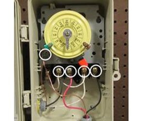
Intermatic t103 wiring diagram. Intermatic T103 Wiring Diagram. Assortment of intermatic t103 wiring diagram. A wiring diagram is a streamlined traditional pictorial representation of an electric circuit. It shows the elements of the circuit as streamlined shapes, as well as the power as well as signal links between the devices. A wiring diagram generally gives information about the… Intermatic T103 Wiring Diagram. Currently, there are two white wires from A & 1 leading to the timer itself. My question is, in which locations (1 thru 4) do I wire the black and. I purchased an Intermatic T timer switch and am unable to get the clock running. This is a wiring diagram for the T is this how you have it wired?. Electrical - AC ... Intermatic T103 Wiring Diagram – One of the most difficult automotive fix tasks that a mechanic or fix shop can assume is the wiring, or rewiring of a car’s electrical system.The trouble really is that all car is different. in imitation of infuriating to remove, replace or repair the wiring in an automobile, having an accurate and detailed intermatic t103 wiring diagram is necessary to the ... on Intermatic T103 Timer Wiring Diagram. Purchased a new T Outdoor Timer. On the inside, there are 5 screws, labeled A, 1, 2, 3, and 4. Additionally, 1 & 3 are labeled 'Line', and 2. The wiring is incorrect. The wiring diagram for that timer is misleading. The volt clock timer motor is connected internally to the "A" (neutral).
07.09.2018 07.09.2018 6 Comments on Intermatic T103 Wiring How to wire Intermatic T and T timers - Hardware & Accessories, Tip, How -To and Do It Yourself Directions. Electrical - AC & DC - Intermatic T Timer Wiring - I had bought a timer I removed the breaker panel and ther are 3 wires going to the timer. Intermatic T103 Wiring Diagram Download. intermatic t103 wiring diagram - Building electrical wiring representations reveal the approximate areas as well as affiliations of receptacles, lights, as well as permanent electrical solutions in a building. Interconnecting wire paths may be revealed about, where specific receptacles or components should be on a common circuit. Intermatic Dial Timer Mechanism For Use With Grainger Items 2e022 4e024 T103 T103p Timers 4a213 T103m. Intermatic t101 timer wiring diagram t103 jpg trouble free pool landscape light two hot wires t104 off state full hooking up pump to relay switch parts dial mechanism for doentation time switches i bought an and wire it model t101m mechanical t7801b manualzz t106r 24 hour dt101 manual pdf ...
Need Help Hooking Up Pool Pump To Relay Switch And Intermatic Mechanical Timer Diy Home Improvement Forum
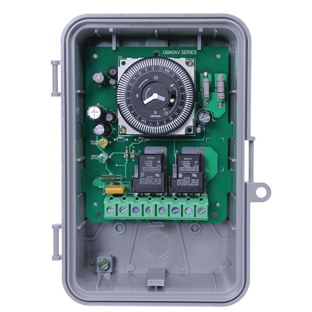
Intermatic Gm40av Series 40 Amp 24 Hour Indoor Outdoor Wall Mounted Autovoltage General Purpose Time Control Gray Gm40av D89 The Home Depot

Anyone Have Any Idea What This Is It S Always Ticking Light Google Search Didn T Produce Much R Homeimprovement

I Bought An Intermatic T103 And Wire It As Follows Power To 1 3 Poles Lights To 2 4 Poles And A Jumper From 3 To










0 Response to "37 intermatic t103 wiring diagram"
Post a Comment