37 iron carbon phase diagram
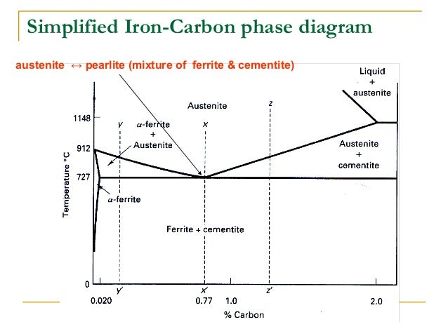
The state diagram of the iron-carbon system is also called the iron-carbon phase diagram. Due to its complexity, the creation of the phase diagram on the basis of selected cooling curves will not be discussed. Furthermore, the iron-carbon diagram in the following sections is initially only considered up to a carbon content of around 2%, as only ... Iron Carbon phase diagram. The austenite-pearlite reaction. Pearlite is the most familiar microstructural feature in the whole science of metallography. It was discovered by Sorby over a century ago, who correctly assumed it to be a lamellar mixture of iron and iron carbide.
Iron carbon phase diagram study guide by given_degrace includes 49 questions covering vocabulary, terms and more. Quizlet flashcards, activities and games help you improve your grades.

Iron carbon phase diagram
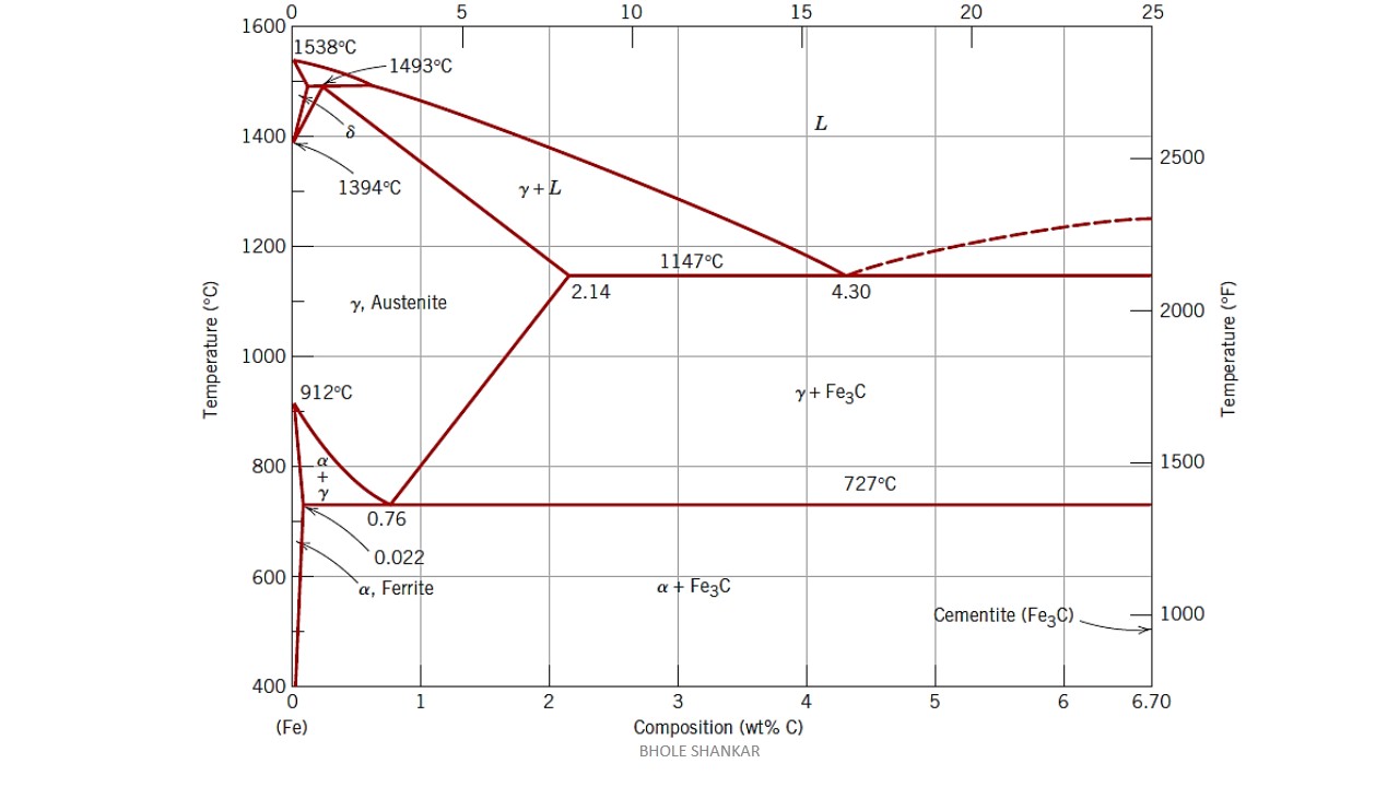
Carbon is the most important alloying element in iron. For this reason, even the smallest changes in carbon content can have massive changes in the characteristics of the material. However, the importance of the iron-carbon phase diagram decreases rapidly if the material is rapidly cooled or heated. The diagram is also less meaningful if the proportion of other alloying elements increases. This iron carbon phase diagram is plotted with the carbon concentrations by weight on the X-axis and the temperature scale on the Y-axis. The carbon in iron is an interstitial impurity. The alloy may form a face centred cubic (FCC) lattice or a body centred cubic (BCC) lattice. It will form a solid solution with α, γ, and δ phases of iron. Hypereutectoid steel: has a carbon content greater than the eutectoid 8 Example: Phase Equilibria For a 99.6 wt% Fe-0.40 wt% C at a temperature just below the eutectoid, determine the following a) composition of Fe 3C and ferrite (α) b) the amount of carbide (cementite) in grams that forms per 100 g of steel
Iron carbon phase diagram. Simplified Iron-Carbon phase diagram austenite ↔ pearlite (mixture of ferrite & cementite) The Austenite to ferrite / cementite transformation in relation to Fe-C diagram. MICROSTRUCTURE OF AUSTENITE. MICROSTRUCTUREOF PEARLITE Photomicrographs of (a) coarse pearlite (b) fine pearlite . 3000X. Dr. Dmitri Kopeliovich Iron-carbon phase diagram describes the iron-carbon system of alloys containing up to 6.67% of carbon, discloses the phases compositions and their transformations occurring with the alloys during their cooling or heating.. Carbon content 6.67% corresponds to the fixed composition of the iron carbide Fe 3 C. . The diagram is presented in the picture: The Iron-carbon phase or equilibrium diagram is an overall study of iron, carbon, and their alloys and how they act under the various equilibrium conditions. In this blog, we studied these aspects of the equilibrium diagram and also how phase transformation depends upon the temperature conditions. Phase Diagram Evaluations: Section II The C-Fe (Carbon-Iron) System by Ho Okamoto ASM International Equilibrium Diagram The number of experimental and theoretical publications on the Fe-C phase diagrams and related subjects is virtually unlimited because of the unqueslionable importance of Fe-C alloys in all as- ...
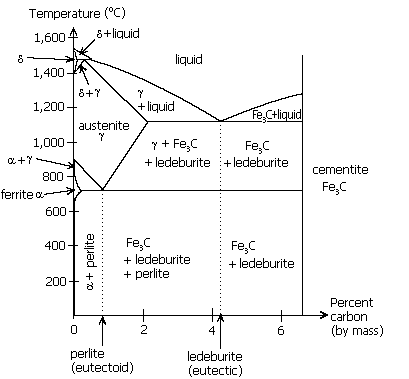
Dr. Ray Taheri, Fe-C phase diagram, Eutectoid Phase transformation 4. Fe-C PHASE DIAGRAM. As mentioned before the Fe-C phase diagram is the representation of all the phases and structures of the alloy iron - carbon based on the different temperature and carbon ... 1. Ferrite: It is a solid solution of upto 0.025% carbon in the solvent a-iron. This phase is indicated in the diagram by GSP. ϒ phase is converted to ferrite due to slow cooling of the solid alloys. Ferrite generally contains no carbon but many other elements such as Mn, Si, Cr in the solid solution. Ferrite is soft, weak and ductile. Iron/Carbon Phase Diagram Iron shows a eutectic with Carbon allowing for a lower melting alloy Body Centered Tetragonal. 6. 7. 8 Carbon content can be reduced by reaction with oxygen and stirring. 9. 10 Eutectoid Steel Pearlite. 11 Time-Temperature-Transformation Diagram. 12 Time-Temperature-Transformation Diagram
In the present investigation, the iron-rich end of the iron copper-carbon phase diagram was studied at 950°C by gas carburization experiments. The solubility of graphite in iron-copper alloys was determined at 950 . 0 , 1000 0 , and 1050 0 C and the solidus temperature was determined for a 90% copper-iron alloy. ... How much carbon can be dissolved in a phase is something that the phase diagram tells you.: Dissolved means that the foreign atoms are sitting as individuals in the crystal (interstitial places for carbon in iron) in some random distribution. In other words: they are extrinsic point defects.Any point inside the blue area in the phase diagram above (the a-phase or ferrite phase) denotes an ... Fig 1 Iron carbon phase diagram. C is an interstitial impurity in Fe. It forms a solid solution with alpha, gamma and delta phases of iron. Maximum solubility of C in alpha iron is 0.025 % at 727 deg C. Body centred cubic (BCC) iron has relatively small interstitial positions. The Iron-Carbon Diagram: A map of the temperature at which different phase changes occur on very slow heating and cooling in relation to Carbon, is called Iron- Carbon Diagram. Iron- Carbon diagram shows - the type of alloys formed under very slow cooling, proper heat-treatment temperature and how the properties of steels and cast irons
Iron Carbon Phase Diagram Drawing Iron Angle White Png Pngegg
The iron-carbon diagramLearning objectives:- You name and describe the different phases of pure iron during the cooling process.- You distinguish between met...

Iron Carbon Phase Diagram A Review See Callister Chapter 9 Pages 1 34 Flip Pdf Download Fliphtml5
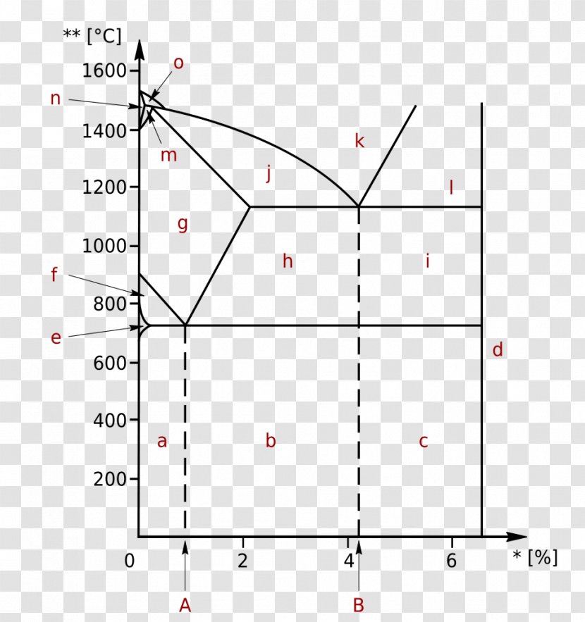
Unit Quiz - The Iron-Carbon System Multiple Choice Identify the choice that best completes the statement or answers the question. Use the diagram to answer the following questions ____ 1. According to the diagram, point "b" is which of the following? a. Iron Carbide c. A hypereutectoid steel b. Alpha Iron d. A hypoeutectoid steel ____ 2.
Iron Carbon Diagram
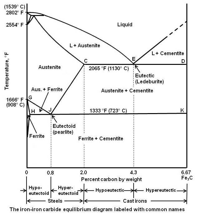
The Iron-Iron Carbide Diagram A map of the temperature at which different phase changes occur on very slow heating and cooling in relation to Carbon, is called Iron- Carbon Diagram. Iron- Carbon diagram shows the type of alloys formed under very slow cooling, proper heat-treatment temperature and how the properties of steels and cast irons can ...
Having Trouble Understanding The Iron Carbon Phase Diagram Chemistry Stack Exchange
The Iron-Carbon Diagram: A map of the temperature at which different phase changes occur on very slow heating and cooling in relation to Carbon, is called Iron- Carbon Diagram. Iron- Carbon diagram shows - the type of alloys formed under very slow cooling, proper heat-treatment temperature and how the properties of steels and cast irons
File Phase Diag Iron Carbon Png Wikimedia Commons
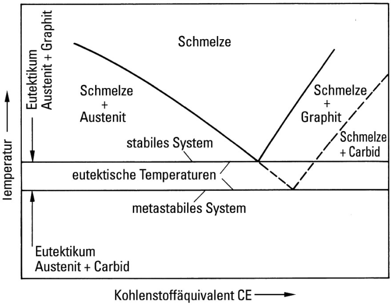
Iron-Cementite diagram is not a true equilibrium diagram, since equilibrium means no change of phase with time, however long it may be. Graphite is more stable form of carbon. Cementite is a metastable phase, which decomposes to graphite if given long periods of time. Graphitisation, however, rarely occurs in steels and may take years to form.
Fe Carbon Phase Diagram Ppt Video Online Download
•Equilibrium iron-carbon phase diagram . White and Malleable Cast Irons • The low-silicon cast irons (<1.0wt.%), produced under rapid cooling conditions • Microstructure: most of cementite • Properties: extremely hard very but brittle • White iron is an intermediate for the production of malleable iron

Iron Carbon Phase Diagram In Their Simplest Form Steels Are Alloys Of Iron Fe And Carbon C The Study Of The Constitution And Structure Of Iron And Steel Start With The Iron Carbon
The simplest phase diagrams are pressure-temperature diagrams of a single simple substance, such as water.The axes correspond to the pressure and temperature.The phase diagram shows, in pressure-temperature space, the lines of equilibrium or phase boundaries between the three phases of solid, liquid, and gas.. The curves on the phase diagram show the points where the free energy (and other ...

Iron Carbon Phase Diagram Engineering Materials
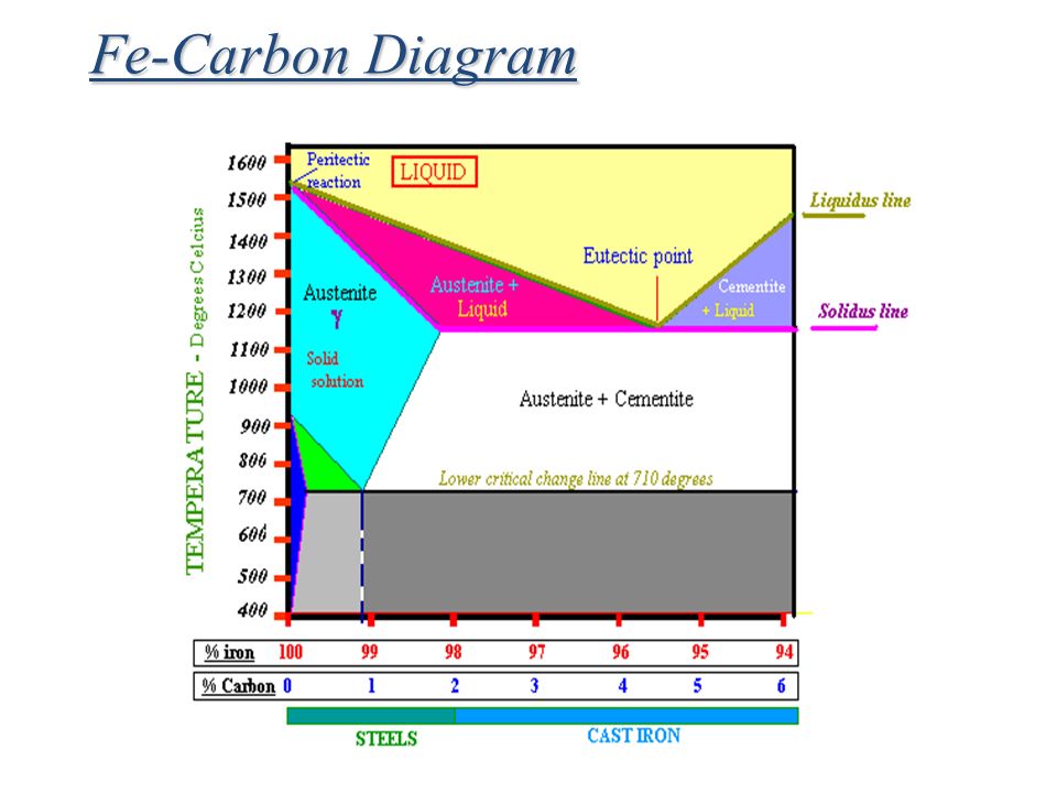
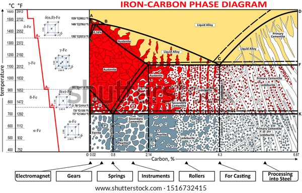
Iron-Carbon Phase Diagram with Detailed Explanation: If the percentage of the carbon is in the range of 0 to 2.11 % then it is called Steel and if the percentage of carbon is in the range of 2.11 to 6.67% then it is called Cast iron. As the carbon content increases, it produces more Iron-Carbide volume and that phase will exhibit high hardness.
Iron Carbon Phase Diagram Steemit
The primary phase of low-carbon or mild steel and most cast irons at room temperature is ferromagnetic α-Fe. It has a hardness of approximately 80 Brinell. The maximum solubility is about 0.02 wt% at 727 °C (1,341 °F) and 0.001% carbon at 0 °C (32 °F). When it dissolves in iron, carbon atoms occupy interstitial "holes". Being about twice the diameter of the tetrahedral hole, the carbon ...

The Iron Iron Carbide Fe Fe3c Phase Diagram Ppt Download
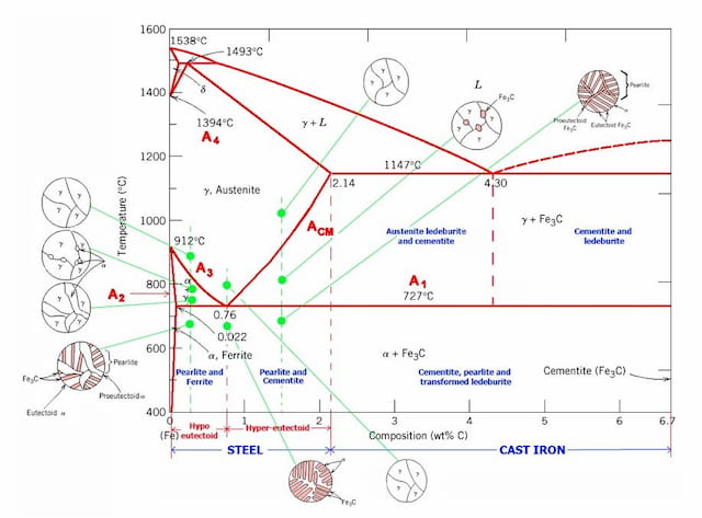
The Iron Carbon Phase Diagram. There is more to the iron-carbon phase diagram than related in the backbone. In particular, there is some nomenclature that I avoided in the main text but that is important for understanding other writings about iron and steel. So let's start with a phase diagram that contains maximal information: A 1: The upper ...
Iron Carbon Phase Diagram Cementite Ternary Plot Iron Transparent Png
The Iron–Iron Carbide (Fe–Fe3C) Phase Diagram In their simplest form, steels are alloys of Iron (Fe) and Carbon (C). The Fe-C phase diagram is a fairly complex one, but we will only consider the steel part of the diagram, up to around 7% Carbon.

Gate Metallurgical Engineering Iron Iron Carbide Phase Diagram
Click here to download pdf notes NOW - http://bit.ly/3lggovpIron Carbon DiagramIron Iron Carbide DiagramIron Carbon Phase Diagram ExplanationIron Carbon Equ...

File Iron Carbon Phase Diagram Svg Wikipedia
Iron Carbon Phase Diagram. At the low-carbon end of the metastable Fe-C phase diagram, we distinguish ferrite (alpha-iron), which can at most dissolve 0.028 wt. % C at 738 °C, and austenite (gamma-iron), which can dissolve 2.08 wt. % C at 1154 °C. The much larger phase field of gamma-iron (austenite) compared with that of alpha-iron (ferrite ...

Iron Carbon Phase Song Youtube
The iron-carbon system (steel and cast iron) MSE 2090: Introduction to Materials Science Chapter 9, Phase Diagrams 2 Component - chemically recognizable species (Fe and C
Introduction To Iron Carbon Phase Diagram Engineering Materials Youtube
Hypereutectoid steel: has a carbon content greater than the eutectoid 8 Example: Phase Equilibria For a 99.6 wt% Fe-0.40 wt% C at a temperature just below the eutectoid, determine the following a) composition of Fe 3C and ferrite (α) b) the amount of carbide (cementite) in grams that forms per 100 g of steel
Iron Carbon Phase Diagram Explained With Graphs
This iron carbon phase diagram is plotted with the carbon concentrations by weight on the X-axis and the temperature scale on the Y-axis. The carbon in iron is an interstitial impurity. The alloy may form a face centred cubic (FCC) lattice or a body centred cubic (BCC) lattice. It will form a solid solution with α, γ, and δ phases of iron.

File Iron Carbon Phase Diagram Svg Wikimedia Commons
Carbon is the most important alloying element in iron. For this reason, even the smallest changes in carbon content can have massive changes in the characteristics of the material. However, the importance of the iron-carbon phase diagram decreases rapidly if the material is rapidly cooled or heated. The diagram is also less meaningful if the proportion of other alloying elements increases.

Iron Carbon Fe C Phase Diagram Ppt Download
Practical Maintenance Blog Archive The Iron Iron Carbide Equilibrium Diagram

4 Iron Carbon Phase Diagram Download Scientific Diagram
2

Scientific Net Publisher In Materials Science Engineering Iron Carbon Phase Diagram Credit Metallurgical Engineering Facebook

Reading The Iron Carbon Phase Diagram Welding Hardfacing Cladding And Cutting Of Metals

Iron Carbon Phase Diagram Google Search Metal Working Tools Metal Working Blacksmithing

Briefly Explain The Eutectic And Eutectoid Reactions In Iron Iron Carbide Fe Fe3c Phase Diagram At What Temperatures And Compositions Percent C Do These Reactions Occur What Are The Phases Before And

Iron Carbon Phase Diagram

The Iron Carbon Alloys And Fe C Phase Diagram Mechanicalbase

Mod 01 Lec 23 Iron Carbon Phase Diagram Youtube

File Iron Carbon Phase Diagram Svg Wikipedia
Iron Carbon Phase Diagram

Iron Carbon Phase Or Equilibrium Diagram Or Iron Carbide Diagram Mechstudies Com
What Is The Use Of An Iron Carbon Diagram Quora

Iron Carbon Phase Diagram Pdf

Iron Carbon Phase Diagram Value Creation From Uzbekistan

Materila Science Engineering Iron Carbon Phase Diagram Slide 5
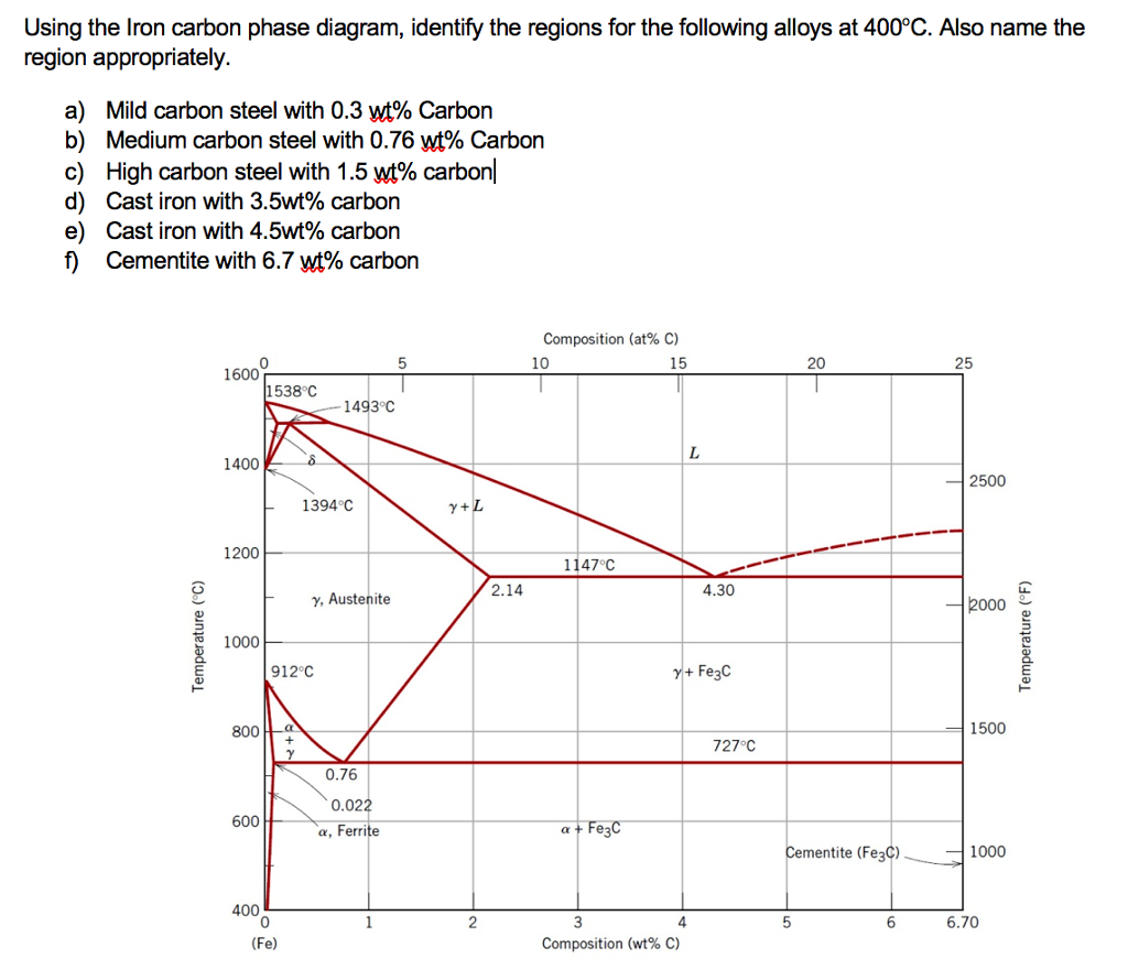
Solved Using The Iron Carbon Phase Diagram Identify The Chegg Com
Vektor Stok Coloring Vector Ironcarbon Phase Diagram Tanpa Royalti 1516732415
0 Response to "37 iron carbon phase diagram"
Post a Comment