37 maxxforce 13 engine diagram
28, — ELECTRICAL CIRCUIT DIAGRAMS. navistar is recalling certain model year through paystar, workstar, transtar, and prostar, and model year and lonestar commercial trucks manufactured from june 1, , through april 4, , equipped with a maxxforce 11 or 13 engine (feature code 12uxj or 12uxh) and with bosch alternator feature codes 08ggn, 08ggr ... Maxxforce 13 Engine Fan Wiring Diagram. 21.12.2018 21.12.2018 0 Comments on Maxxforce 13 Engine Fan Wiring Diagram, , RXT Models Built March 1, to March 18, — ELECTRICAL CIRCUIT DIAGRAMS .. FAN WIRING, ISM, C11-C13 ENGINES, P. 2. Low prices on Engine Cooling Fan Controller for your International ProStar at Advance Auto Parts.
2 ®2010 MaxxForce 11 and MaxxForce® 13 Engine Training Program The front gear train is located behind the front cover. The gear train drives the oil pump, low-mount cooling fan, and the accessory drive assembly. The fuel filter module and high-pressure fuel pump are located on the left side
Maxxforce 13 engine diagram
This document will address the unique data plate functionality for the MaxxForce® 11 and 13. Description and Operation The Data Plate reports stored Engine Control Module (ECM) information to help identify vehicle and engine components. Programmable Parameters The following programmable parameters are for display only with the Data Plate ... rocker bolts (Figure 6). Torque the injector harness nuts down to 1.5 NM or 13 IN-LBS and make sure the valve cover goes on without interfering with the harness. IK1200484 MaxxForce® 11 and 13 Injector Harness Installation Procedures Page 4 of 5 Maxxforce 11 y 13. maxxforce 13 engine fan wiring diagram. maxxforce 13 wiring diagram. We collect a lot of pictures about International Maxforce 13 Ecm Wiring Diagram. and finally we upload it on our website. Many good image inspirations on our internet are the best image selection for International Maxforce 13 Ecm Wiring Diagram. .
Maxxforce 13 engine diagram. Valves, and Actuators NOTE: Refer to the following publications for information on diagnostics and troubleshooting: EGES-420 International MaxxForce 11 and 13 Diagnostic Manual EGED-425 International MaxxForce 11 and 13 Engine Performance Form EGED-430 International MaxxForce 11 and 13 Engine Wiring Diagram EGED-435 International MaxxForce 11 ... The 2010+ International MaxxForce 11 and 13 diagnostic manual covers symptom- and code-based diagnostics for the engine and ECM. Chapters include step-by-step troubleshooting as well as complete diagnostic specifications. This manual is intended for professional diesel mechanics. Latest edition, 2017. Large format wiring diagram sold separately ... MaxxForce® 11 and 13. Description and Operation The Engine Retarder feature is activated by pressing the service brake pedal or by releasing the accelerator pedal which is dependent upon customer programming. The Engine Retarder feature consists of two operator control switches: Engine Retarder ON/OFF switch and the level selection switch. International® MaxxForce® 11 and 13 Engine Wiring Diagram EGED-435 International® MaxxForce® 11 and 13 Signal Values (available on ISIS® only) Technical Service Literature is revised periodically and mailed automatically to "Revision Service" subscribers. If a technical publication is ordered, the latest revision will be supplied.
MAXXFORCE ® 11L & 13L BASIC ENGINE WARRANTY †Towing applies only for vehicles with engine-related failures and is otherwise covered for the first 90 days. With an unsurpassed B-50 rating of 1.2 million miles—engine life that helps your business go on without interruption—your MaxxForce ® engine can be counted on to show up for work ... The contents of this forum are for experimental & educational purposes only. As such, it is not acceptable whatsoever to publish any software that is bound by any legal restriction. Many good image inspirations on our internet are the most effective image selection for maxxforce 13 engine diagram. 10 maxxforce dt engine thanks for visiting our site this is images about 10 maxxforce dt engine posted by ella brouillard in 10 category on oct 25 2019. Remote radio namp and nwired remote and ndriver interface display. MaxxForce DT, 9, 10 (2010 - 2013) Engine Wiring Diagram Page 1 of 3 B A 1 2 2 3 1 4 ... Engine to Chassis (6011) 12 1 13 24 1 3 Aftertreatment DOC Flow DPF Exhaust Sensors 2 1 2 1 2 1 EFP PWR EGRP Radiator ... Engine Wiring Diagram Page 2 of 3 86-Pin Connector (6341) 53-Pin Connector (6340) Twisted pair
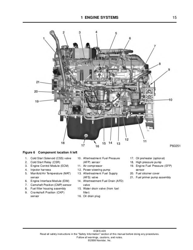
MaxxForce® 11 and 13 engines use a dual stage, fixed geometry turbocharger assembly. The high-pressure (HP) turbocharger includes a. ENGINESYSTEMS 11 pneumatically operated wastegate. Each stage usesaChargeAirCooler(CAC).TheLowPressure ChargeAirCooler(LPCAC)ismountedonthelower maxresdefault. maxxforce13. Paccar MX 13 engine. We collect lots of pictures about Maxxforce 13 Engine Diagram. and finally we upload it on our website. Many good image inspirations on our internet are the most effective image selection for Maxxforce 13 Engine Diagram. . If you are pleased with some pictures we provide, please visit us this ... 2013 Maxxforce DT, 9, 10 Wiring Diagrams. Download now. Jump to Page . You are on page 1 of 591. Search inside document . EPA 10 - US, Canada, Mexico. MaxxForce 11 and 13 ENGINE® SERVICE MANUAL ENGINE SERVICE MANUAL ... MaxxForce® 11 and 13 engines are equipped with Exhaust gas flow: ... MaxxForcefi 11 and 13 Engine Wiring Diagram 2 EGES420-2 Low Pressure Fuel System EGES420-2 High Pressure Fuel System EGES420-2 Fuel Quality Engine Diagnostic Manual for MaxxForcefi 11 and 13 Fuel System EGES420-2 IK1200464 MaxxForce® 11 and 13 Fuel System Diagnostic Codes and Diagnostic StepsPage 6 of 6
EGED-430-2 - Engine Wiring Diagram Maxxforce 11 and 13 2008 Model Year.pdf EGED-435 - Maxxforc ETM 11 and 13 2008 Model Year Signal Values (All values with the breakout box installed on the ECM, EIM, ACM, and harness).pdf
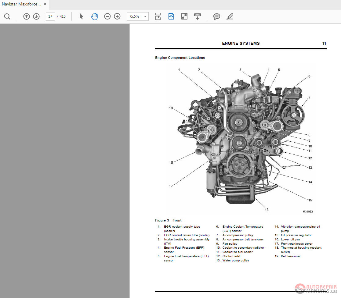
Navistar Maxxforce 7 2007 Engine Service Manual Auto Repair Manual Forum Heavy Equipment Forums Download Repair Workshop Manual
It is applied to large volume or large quantity SF6 gas storage in gaseous and Cars, Railroad - MAXXFORCE 13 ENGINE OIL TEMPERATURE SENSOR Accelerator pedal is pressed or Accelerator Pedal Position sensor (APP) GND A F + R4 MaxxForce DT, 9, 10 ( - ) Engine Wiring Diagram. APS/IVS Accelerator position signal in range DTC APS/IVS Install the 5 ...
- The Engine Coolant Temperature 1, or ECT1, sensor is located on the EGR Coolant Return Manifold. - The Engine Oil Temperature, or EOT, sensor is located on the Oil Filter Module flange elbow. Rear of Engine - The Crankshaft Position, or CKP, sensor is located on the top left of the flywheel housing. NOTES
MaxxForce DT engine pdf chiral download. Also for: Maxxforce 9, Maxxforce 10, Maxxforce 11, Maxxforce 13, Maxxforce 15. Page 140 DIAGNOSTIC MANUAL The anatomic diagram for the Aftertreatment (AFT) arrangement includes the following: • Engine Control Module (ECM) with Barometric..Maxxforce Dt Engine Diagram.Oct 28 2021. We accommodate you this able as cautiously as accessible affectation to ...

International Prostar 2012 With Maxxforce 13 Engine Vin Cn620737 It Had Engine Fan Failure 2 4 Years Ago And Dealer
Many good image inspirations on our internet are the most effective image selection for maxxforce 13 engine diagram. 10 maxxforce dt engine thanks for visiting our site this is images about 10 maxxforce dt engine posted by ella brouillard in 10 category on oct 25 2019. Remote radio namp and nwired remote and ndriver interface display.
This wiring diagram is intended to be used with the 2010-2013 International MaxxForce 11, 13 Engine Diagnostic Manual. View the manual on your computer, tablet or have it printed in large format without restrictions.
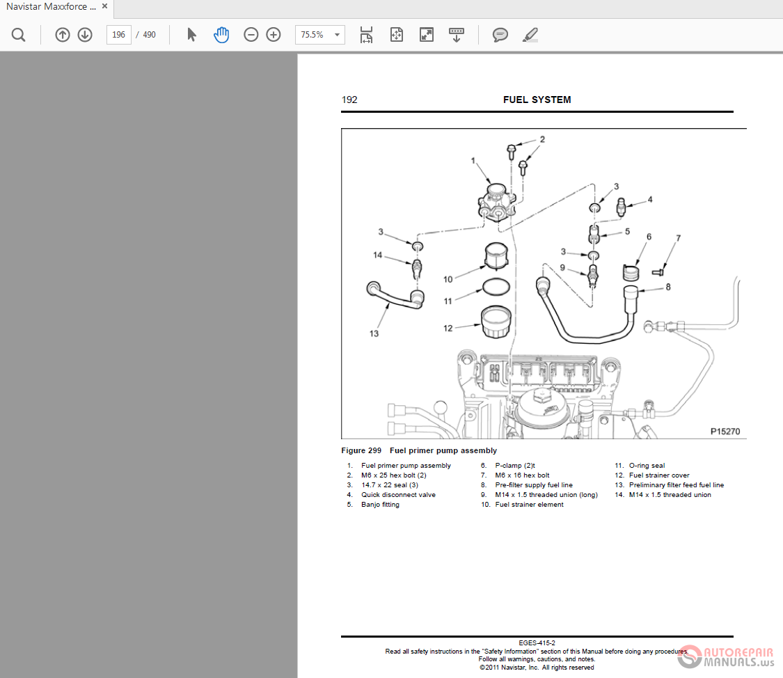
Navistar Maxxforce 11 13 Eges 415 2 2011 Engine Service Manual Auto Repair Manual Forum Heavy Equipment Forums Download Repair Workshop Manual
S#: 125HM2Y4182687. This 2012 International MaxxForce 13 430 HP Engine is available at TCS in Strafford, MO! Call (866) 318-9827 for more details or visit us...
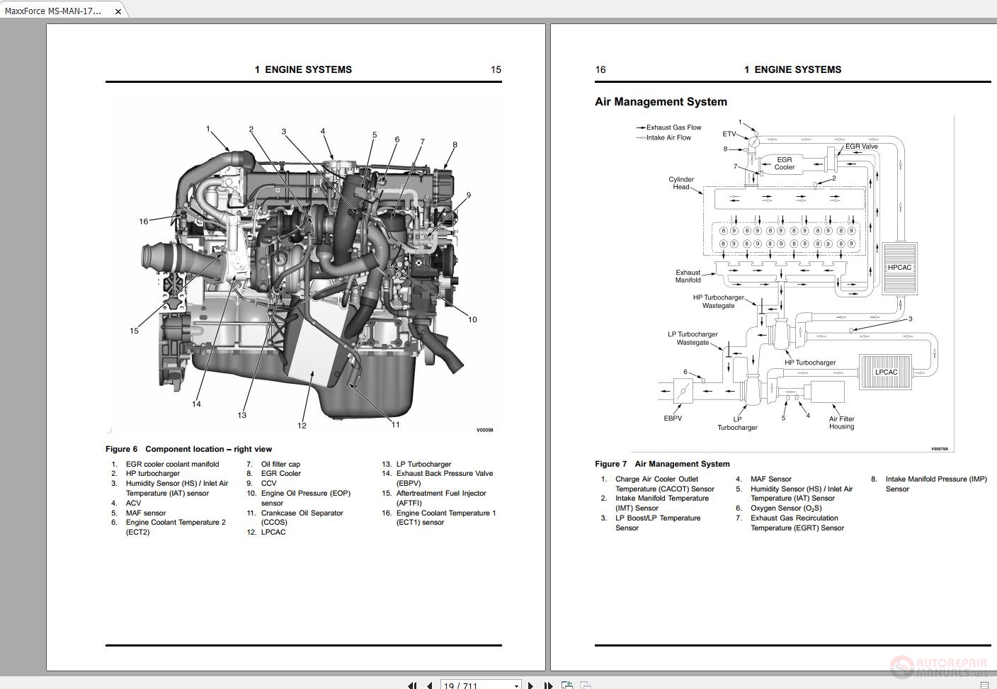
Navistar Maxxforce Ms Man 1741 11 13 Epa10 Diagnostic Manual Auto Repair Manual Forum Heavy Equipment Forums Download Repair Workshop Manual
1171971R1 MaxxForce ... supply pressurized oil to engine components. All MaxxForce ... 13. EngineThrottleValve(ETV) 14. Turbochargerinletduct assembly 15. Turbochargeroilsupplytube 16. Low-pressureturbocharger assembly 17. Drafttube
on the diagram (page 8). c. ECT1 is located at the rear of the engine and is difficult to access. The ResistorPac will therefore be installed into the wiring at the ECU. THE ARROW POINTS TO THE DIFFICULT LOCATION OF THE COOLANT TEMPERATURE SENSOR d. The signal wire from ECT1 connects to Pin E1-14 at the ECU. E1 is the 96-pin connector. e.

Navistar Maxxforce 7 2010 Engine Diagnostic Manual Auto Repair Manual Forum Heavy Equipment Forums Download Repair Workshop Manual
I have a couple of Volvo 670s w/ Cummins ISX engines, and I was looking to replace one with a 2012-13 ProStar. I am pretty happy with the ISX other than an EGR problem every 200,000 miles. But I can't help but notice that there is a $15-20000 price difference(30+%) between the price of ProStars equipped with the MaxxForce engine and the Cummins ...
Download scientific diagram | Schematic of Navistar MaxxForce 13 heavy-duty dual-fuel compression ignition engine test bed. from publication: Modeling and control of fuel distribution in a dual ...
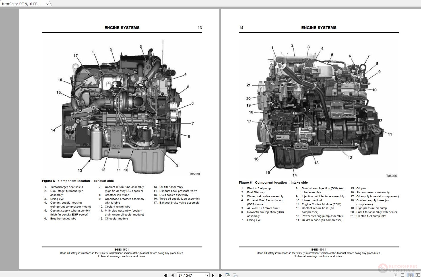
Navistar Maxxforce Dt 9 10 Epa10 Diesel Engine Service Manual Auto Repair Manual Forum Heavy Equipment Forums Download Repair Workshop Manual
Maxxforce 11 y 13. maxxforce 13 engine fan wiring diagram. maxxforce 13 wiring diagram. We collect a lot of pictures about International Maxforce 13 Ecm Wiring Diagram. and finally we upload it on our website. Many good image inspirations on our internet are the best image selection for International Maxforce 13 Ecm Wiring Diagram. .
rocker bolts (Figure 6). Torque the injector harness nuts down to 1.5 NM or 13 IN-LBS and make sure the valve cover goes on without interfering with the harness. IK1200484 MaxxForce® 11 and 13 Injector Harness Installation Procedures Page 4 of 5
This document will address the unique data plate functionality for the MaxxForce® 11 and 13. Description and Operation The Data Plate reports stored Engine Control Module (ECM) information to help identify vehicle and engine components. Programmable Parameters The following programmable parameters are for display only with the Data Plate ...

Maxxforce Engine 11 13 15l Cummins Isx N13 Wiring Diagram Auto Repair Software Auto Epc Software Auto Repair Manual Workshop Manual Service Manual Workshop Manual









0 Response to "37 maxxforce 13 engine diagram"
Post a Comment