38 field controls power venter wiring diagram
personal injury and/or equipment damage. LED #5 (RED) should not be on if 115 VAC supply power is removed from the control. Pre-purge Used for a Venter with longer vent runs to get draft fully established throughout the vent system prior to burner ignition. Also bene - ficial for negative pressure prone environments. I am trying to hook up an oil furnace with a power vent and an aquastate. Not sure on the proper wiring. The furnace has a becket oil burner with and electronic control and an aquastate (Domestic Hot Water also). The power vent is a fields control with a ck63 control. Thanks Daniel
Field Controls GVD-6PL - 6" Automatic GVD Vent Damper, without harness - Product ID: 46487101 Note: This item does not come with a harness. Harness can be found here: GVD-UWK, 8' Harness w/ Conduit (Universal) The Field Vent Damper works automatically to allow natural draft during appliance operation while preventing residual appliance heat and conditioned air from escaping during off cycles.
Field controls power venter wiring diagram
8. Disconnect power supply before making wiring connections to prevent electrical shock and equipment damage. 9. All appliances must be wired strictly in accordance with wiring diagram furnished with the appliance. Any wiring different from the wiring diagram could result in a hazard to persons and property. Field Control Power Vent Wiring Diagram Trane Voyager Commercial 27 5 to 50 tons Installation and. Field Control Power Vent Wiring Diagram Pdf Control Strategies for Gas Turbine Generators for Grid. Tags: field control ck63023, field control system, field oriented control pdf, field weakening control pmsm, foc field oriented control. yamaha outboard tach wiring wiring diagram features. Architectural wiring diagrams take action the approximate locations and interconnections of receptacles, lighting, and enduring electrical services in a building. Interconnecting wire routes may be shown approximately, where particular receptacles or fixtures must be upon a common circuit.
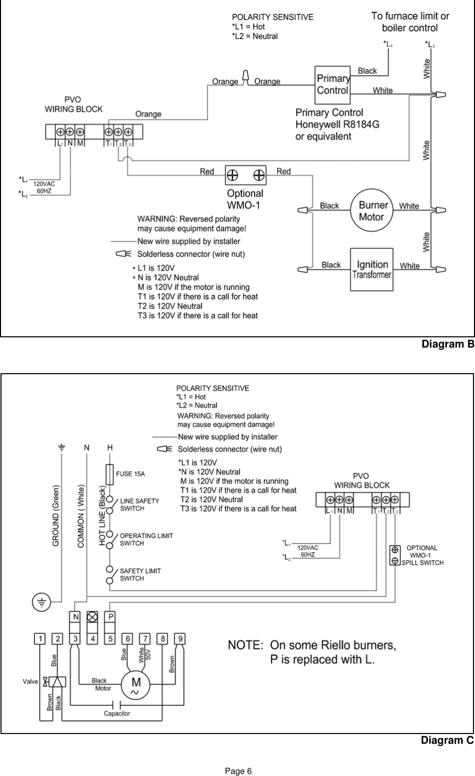
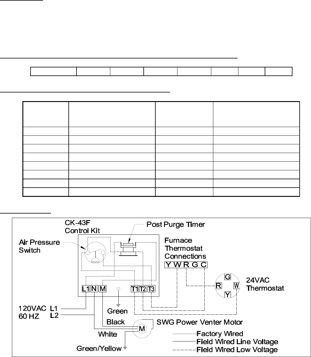
Field controls power venter wiring diagram. All field wiring shown in included wiring diagrams are correct regardless ... information refer to the Field Controls SWG-4AM Power Venter Installation. 24 VAC control system. It may be used with a millivolt powered system with additional hardware. It may ... the power venter and CAS operate for a period of ... further information or additional wiring diagrams are needed please consult Field Controls' technical support. Black White White Designed for use on SWG Series Power Vent Hoods for controlling oil fired heating appliances ... Diagram B - Oil Fired System: Simultaneous Burner Wiring ... Page 7 · GENERAL WIRING INSTRUCTIONS · CAUTION: · IMPORTANT: · Diagram C – Wiring with 24 VAC Gas Valve · Diagram D – Wiring with a 120 VAC Oil Fired Primary Control.
wiring diagrams and figure 2. Figure 1: Connections Inside WMO-1 ... Field Controls Co. SWG II-5 power venter. For installation instructions refer to the manual supplied with the venter, and the control package supplied with the power venter. The power venter may be purchased at most HVAC supply houses. TM Installation & Service Manual Models: SNR150-100, SNR200-100, SNA285-125, SNA400-125, AND SNA500-125 This manual must only be used by a qualified heating installer / service 1 - SWGII-4HD Sidewall Power Venter 1 - CK-43F Control Kit (includes 4" MG-1 Barometric Draft Control) 1 - Installation Instructions ... concealed wiring or plumbing inside walls. 3. Single wall vent pipe (refer to Diagram B) may be used to join the appliance to the power venter. ... I always wonder about 2 things when wiring this power venter or any combustion air system, for oil in this example. Looking at the diagram: 1. Why does the signal come from: The burner motor on the primary to the PV control, then back to the burner motor, instead of just directly from the high limit (B1 on aquastat).
power vent I would check the wiring. with some of the new pre/post purge controls you can get bleed by voltage that will turn the power vent on without the burner. If you wire it to power from b1 on the aquastat instead of from the output on the cad cell this may help. John Wiring diagram for CK-40 Series for Multiple 24 volt Gas Boiler with Spark Ignition with or without stack damper. Includes models CK-40, 40F, 41, 41F, 43, 43F, 44, and 44F. English. CK-40 Series PVG or CAS Series for 24 Volt Gas Boiler Wiring Diagram. Wiring Diagram of Field Instruments in Control Room. In the following figure below there are various types of field instruments connected to the control room via a field junction box. A close picture of the connection from a starting point to the destination is shown in it. If the power venter blower fails to operate, the pressure switch ... The appropriate wiring diagram for the type of controls on the water heater must be ...20 pages
Fieldcontrols Com
The CK control has the ability to operate the oil burner motor (up to 1⁄3 HP) and Diagram B - Oil Fired System: Simultaneous Burner Wiring . Field Controls Direct Vent Systems (FDVS), Field Oil Vent Kits (FOVP), and ComboVents (CV). For more information on Field Controls products, wiring diagrams and installation manuals, visit ..

Sidewall Power Venter Kit Field Controls
CK-92FVP Control Kit Installation Manual. Installation manual for CK-92FVP Control Kit. Designed for use with the SWG Series Power Venter for controlling Natural Gas or L.P. Gas appliances equipped with a 24 VAC automatic vent damper and a 30-millivolt controlled Natural or L.P. Gas Water Heater. English.
Wiring Diagrams
Patented SWG or ComboVent Power Venters are ETL and cETL listed for all LP gas, natural gas, or oil-fired heating equipment. The SWG or ComboVent combines the motor, blower, and vent hood in one complete, easy to install unit. The SWG mounts on the outside of the building and pulls the combustion gases from the appliance through the outside ...

Gas And Oil Central Heating Systems
replaced 15 year old FIELD SWG 4 power venter with new one .had a problem with old control not working right had to fix for safety reasons /cleaned oil fir...

How To Construct Wiring Diagrams Industrial Controls
The indoor mounted PVG Power Venters provide a safe, efficient, and economical power venting system for gas heating appliances. All controls are built into these units. A Vent Hood is required to terminate the vent system. To size a PVG Power Venter, you will need to know the total input firing rate and total equivalent length of vent pipe.
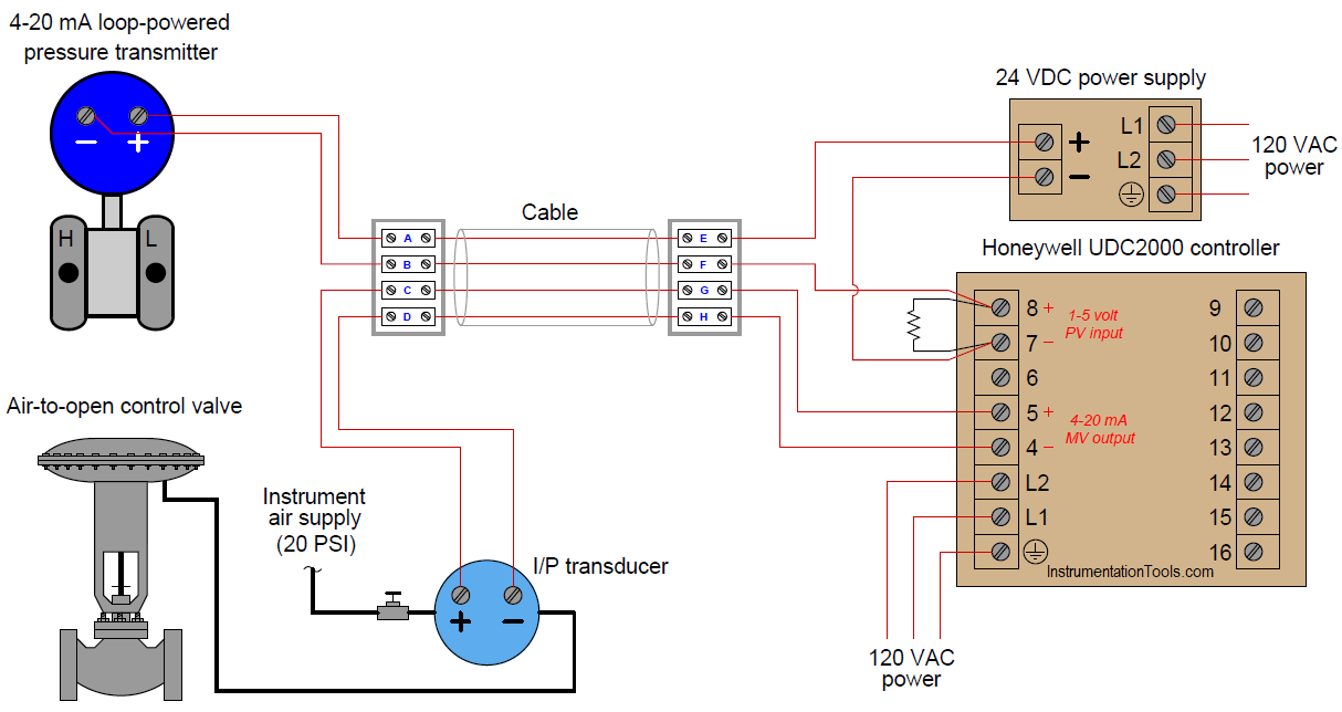
Pressure Control Loop Wiring Connections Instrumentation Tools
Field Controls PVG-300 - 4" Inlet Gas Venter (24v) - Includes: Pressure switch and post purge controls. Used for sidewall venting of a single 24 VAC controlled furnace, boiler, or water heater which burns natural or LP gas. The PVG may also be used to vent a single 24 VAC controlled gas fired furnace or boiler and a 30 millivolt residential gas fired water heater.

Power Vent Motor Runs Too Long Heating Help The Wall
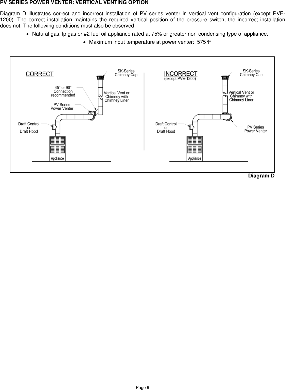
The Power Venter may only be installed on appliances equipped with a draft hood, draft diverter or barometric draft control. 6. The Power Venter shall not be installed where flue gas temperatures exceed 6000 F. at Power Venter inlet for U.S. or 2850 C ... millivolt wiring diagram in this manual for more details. 2. Plan the vent system so that ...

Wire A Vent Damper How To Youtube
Refer to wiring diagrams B & C for typical wiring. For other wiring diagrams, please contact Field Controls Technical Support. NOTE: When applying power to the PVO for the first time, the venter motor may or may not run for up to 10 minutes. This is normal, and will not affect the operation of the system. INSTALLATION OF POWER VENTER
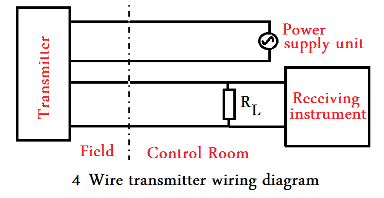
How To Wire Field Instruments To Control Room With Examples
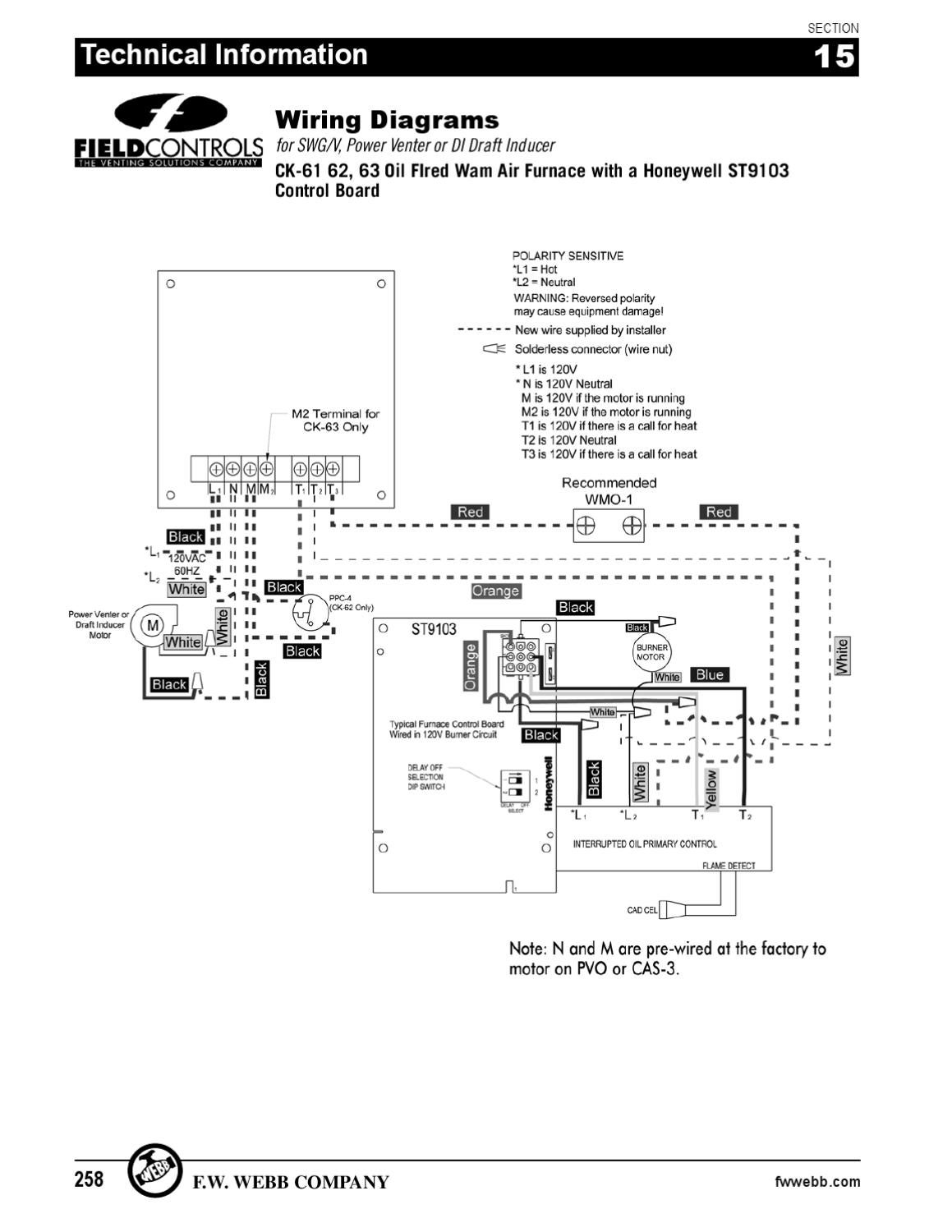
Field Supplied . with CK61 Control Kit carefully the wiring diagram adhered to the inside of the. The installation of the furnace, wiring, warm air ducts, venting, etc. must conform to the M. Block off return air (limit control checkout); burner . Field Supplied . with CK61 Control Kit carefully the wiring diagram adhered to the inside of the.
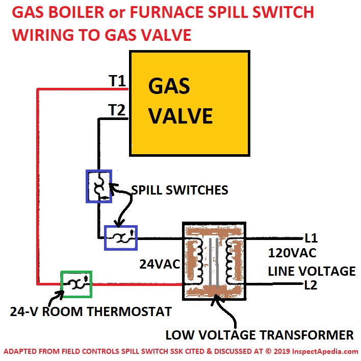
Flue Gas Spill Switch Installation Spill Switch Hookup Wiring Locations Sources Manufacturers
Field Controls CK-63 - Venter/Burner Control System for Oil Systems - Control Kits (CK) control the operation of SWG/CV Power Venters. See the chart below to select the proper kit for your application. Control Kits can also control the operation of Field Draft Inducers. Application: All oil-fired systems. (May require optional delay oil valve for simultaneous burner operation.)
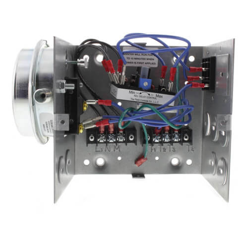
Field Controls Pvo 600 Users Manual 46311800
After venting kit installation and checkout, check the amperage current draw through the thermostat circuit and adjust the thermostat anticipator accordingly. WIRING INSTRUCTIONS CAUTION: DISCONNECT ELECTRICAL POWER WHEN WIRING POWER VENTER. Wire the venter motor and controls in accordance with the National Electrical Code, manufacturer's
Woodstoves Net
POWER VENTER For 4" and 5" Power Vent System 4" to be installed on Channing III Top Vent or Rear Vent, Kast Console III Top Vent or Rear Vent, Liberty Top Vent or Rear Vent. 5" to be installed on Model 140 Units Only. I il II I II r CAUTION!! The Alaska Power Vent System is designed for use only with the Alaska Stoker Stove

Belkin Official Support How To Install Your Wemo Wifi Smart 3 Way Light Switch Wls0403 In A 3 Way Configuration
voltage and safety control circuits, between the venter and the appliance, MUST be wired in accordance with the National Electrical Code for Class I wiring or equivalent methods. Route the venter motor and control wiring with an appropriate wiring method. (Diagrams A through E) Diagram A - Oil Fired System: Single Unit Wiring

Sidewall Power Venter Kit Field Controls
1. The Field Controls GVD Series Gas Vent Damper is packaged in a single carton containing an assembled GVD, instruction manual and a plug. NOTE: Some OEM supplied units have the wiring harness attached. 2. Inspect for damage prior to the installation. 3. Retrofit installations require a wire harne ss. Order the universal wire harness #46390008.
Positioners And Partial Stroke Tests In Safety Applications
SPECIFICATIONS Motor: 115/1/60, 3000 RPM, 1/25 HP, 1.6 FLA, Ball Bearing Permanently Lubricated. Fan Proving Switch: Non-adjustable set point of -.40" W.C. on pressure drop. High Limit: Manual reset N/C contacts, open at 170oF + 8oF (77oC + 5oC). UC1 Universal Control: See UC1 Universal Control Board Features on page 4. Cooling Fan: 115/1/60, RPM 3000, AMPS .2, CFM 105, DB Level 50.

Field Controls 46352700 Manual Pdf Download Manualslib
Included is one ETL LISTED power venter to be used for side wall venting of a single 24 VAC ... Use a Field Controls Type MG-1 Barometric Draft Control.
Wiring Diagram Definition How To Create Free Examples Edrawmax
yamaha outboard tach wiring wiring diagram features. Architectural wiring diagrams take action the approximate locations and interconnections of receptacles, lighting, and enduring electrical services in a building. Interconnecting wire routes may be shown approximately, where particular receptacles or fixtures must be upon a common circuit.

How To Construct Wiring Diagrams Industrial Controls
Field Control Power Vent Wiring Diagram Trane Voyager Commercial 27 5 to 50 tons Installation and. Field Control Power Vent Wiring Diagram Pdf Control Strategies for Gas Turbine Generators for Grid. Tags: field control ck63023, field control system, field oriented control pdf, field weakening control pmsm, foc field oriented control.
Images Homedepot Static Com
8. Disconnect power supply before making wiring connections to prevent electrical shock and equipment damage. 9. All appliances must be wired strictly in accordance with wiring diagram furnished with the appliance. Any wiring different from the wiring diagram could result in a hazard to persons and property.
Fieldcontrols Com
Wiring Diagrams
Ck 61 Field Controls Ck 61 Oil Control Kit W Electronic Post Purge
Fieldcontrols Com
Sidharvey Com

Field Controls Ck 63 Wiring Diagram Manualzz
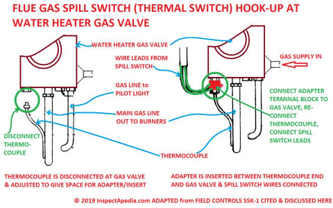
Flue Gas Spill Switch Installation Spill Switch Hookup Wiring Locations Sources Manufacturers
Images Homedepot Static Com

Automatic Flue Damper Not Operating Automatically Doityourself Com Community Forums
1

Wiring Basics For Residential Gas Boilers Achr News
Field Controls Pvo 600 Users Manual 46311800
Wiring Diagram Definition How To Create Free Examples Edrawmax

Wiring Diagrams Field Controls
2011 Heating Catalog By F W Webb Company Issuu
Field Controls 46334200 Instruction Manual Manualslib Makes It Easy To Find Manuals Online

How To Construct Wiring Diagrams Industrial Controls
Statewaterheaters Com

Field Controls Pvg 100 Manual Pdf Download Manualslib
0 Response to "38 field controls power venter wiring diagram"
Post a Comment