39 draw the free-body diagram for the boom. connection at a is a pin.
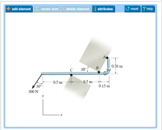
In a free-body diagram we draw the system somewhat realistically and replace ... To get a feeling for the force at a pin connection consider the physical ... Free-Body Diagram.The x, y, z axes are established at B and the free-body diagram of segment AB is shown in Fig. 1-8b.The resultant force and moment components at the section are assumed to act in the positive coordinate directions and to pass through the centroid of the cross-sectional area at B. The weight of each segment of pipe is
Pin Connection at A Ball & Socket at A. Frames and Machines Example: Free Body Diagrams Draw FBD of (a) Each member (b) Pin at B, and (c) Whole system. Example Members ACE and BCD are connected by a pin at C and by the link DE. For the loading shown, determine the force in link DE and the

Draw the free-body diagram for the boom. connection at a is a pin.
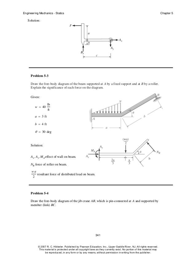
Engineering Mechanics - Statics Chapter 5 Problem 5-10 Draw the free-body diagram of the beam, which is pin-connected at A and rocker-supported at B. Given: F = 500 N M = 800 N⋅ m a = 8m b = 4m c = 5m Solution: Problem 5-11 The sphere of weight W rests between the smooth inclined planes. Determine the reaactions at the supports. 37 Free Body Diagrams Wednesday, October 3, 2012 New Support Conditions Pin Connection ! Another way Here is a pin support 38 Free Body Diagrams Wednesday, October 3, 2012 New Support Conditions Pin Connection ! On a pin, we know that there is an x and a y component of the reaction but without other 5.4 Draw a free body diagram of the automobile side mirror pictured, by ... Calculate the reaction forces at the pin at point A and the roller at point B.126 pages
Draw the free-body diagram for the boom. connection at a is a pin.. Draw the free-body . diagrams for each pipe and . both pipes together. 5-10 Free-Body Diagrams. Solution For idealized models, Free-Body Diagram of pipe A. 5-11 p.216, 5-9. Draw the free-body diagram of the beam, which is pin- connected at A and rocker-supported at . B. 5-12 A short video to show how to form an imaginary cut and draw a free body diagram of a simply supported beam with a point load.Related videos:Reactions of a Si... Sec. 3.2 Free-Body Diagrams in the Equilibrium of a Rigid Body 119 Problem 3. 2-2 Draw the free-body diagram of the jib crane AB, which is pin-connected at A and supported by member (link) BC. Neglect the weight of the crane. 8 kN 3 m 0.4 m A C B 3 4 5 4 m Solution 1. Free-Body Diagram 4 - 4 The first step in the static equilibrium analysis of a rigid body is identification of all forces acting on the body with a free body diagram. • Select the body to be analyzed and detach it from the ground and all other bodies and/or supports. • Include the dimensions, which will be needed
Drawing Free-Body Diagrams. Free-body diagrams are diagrams used to show the relative magnitude and direction of all forces acting upon an object in a given situation. A free-body diagram is a special example of the vector diagrams that were discussed in an earlier unit. These diagrams will be used throughout our study of physics. • A free body diagram of the complete frame is used to determine the external forces acting on the frame. • Internal forces are determined by dismembering the frame and creating free -body diagrams for each component. • Forces between connected components are equal, have the same line of action, and opposite sense. Knowing that 8 kNAF and 16 kN,BF determine the magnitudes of the other two forces. SOLUTION Free-Body Diagram of Connection 3 3 0: 0 5 5 x B C AF F F F With 8 kN, 16 kNA BF F 4 4 16 kN 8 kN 5 5 CF 6.40 kNCF 3 3 0: 0 5 5 y D B AF F F F With AF and BF as above: 3 3 16 kN 8 kN 5 5 DF 4.80 kNDF 154 155. Free Body Diagrams. A free body diagram is a tool used to solve engineering mechanics problems. As the name suggests, the purpose of the diagram is to "free" the body from all other objects and surfaces around it so that it can be studied in isolation. We will also draw in any forces or moments acting on the body, including those forces and ...
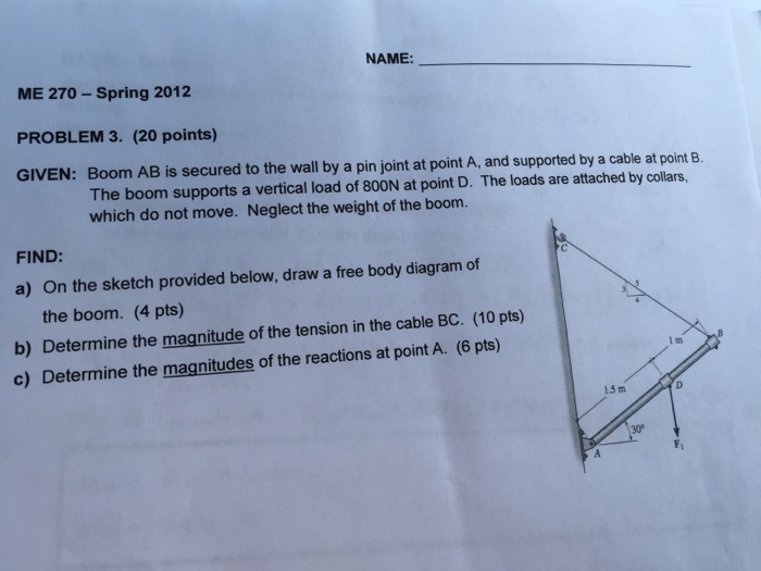
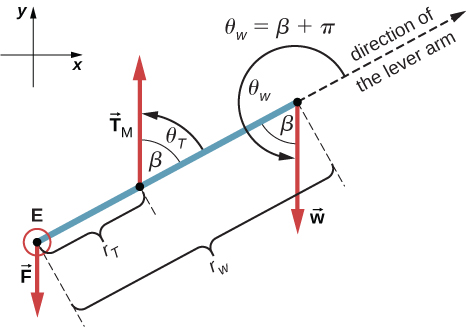
5—6. the free-body diagram af the crane boom AB which has a weight of 650 1b and center of gravity at G. The boom is supported by a pin at A and cable BC. The load of 1250 1b is suspended from a cable attached at B. Explain Lhc significance of each force acting on the diagram. (See Dr. Ahmed A. Abu-foul T.A: Eng. Waseem (Younis 30 sithBo COS So Draw the free-body diagram of the beam, which is pin- connected at A and rocker-supported at B. Page 12. 5-12. 5.3 Equations of Equilibrium. ▫ For ...55 pages PROBLEM 2.F8 A transmission tower is held by three guy wires attached to a pin at A and anchored by bolts at B, C, and D. Knowing that the tension in wire AB is 630 lb, draw the free-body diagram ... Pin-Connected Frame. For rigid plane frames, there are three requirements for complete analysis: (1) finding the values of the reaction components, (2) modelling how the principal stresses (axial, shear, and moment) act on the structure, and (3) determining the deflected shape. An interesting feature of this problem is that we have an internal ...
Free-Body Diagram: For no motion, reaction at . A must be downward or zero; smallest distance a for no motion corresponds to A = 0. + SM B = 0 200 150 150 50 200 300 0: ( )( ) ( ) ( )( ) ( )N mm N N mm mm- - + +a a A= A a = (200 20000- ) 300
pin in joint B. See the diagram in the lower right of Figure 3-2. Step 2: The set of free-body diagrams is shown in Figure 3-3. Step 3: Now consider the free-body diagrams of all of the members in Figure 3-3. We have already discussed member 1, recog-nizing it as a two-force member in tension carrying forces RA and RC equal to 48.07 kN.
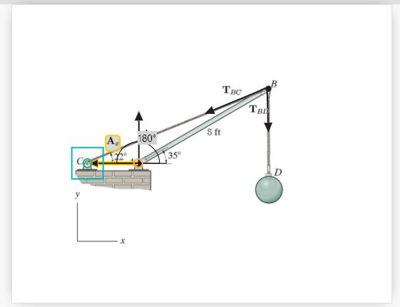
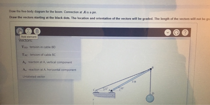
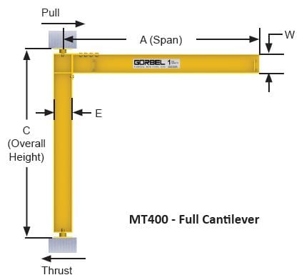
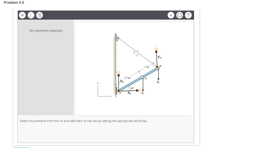
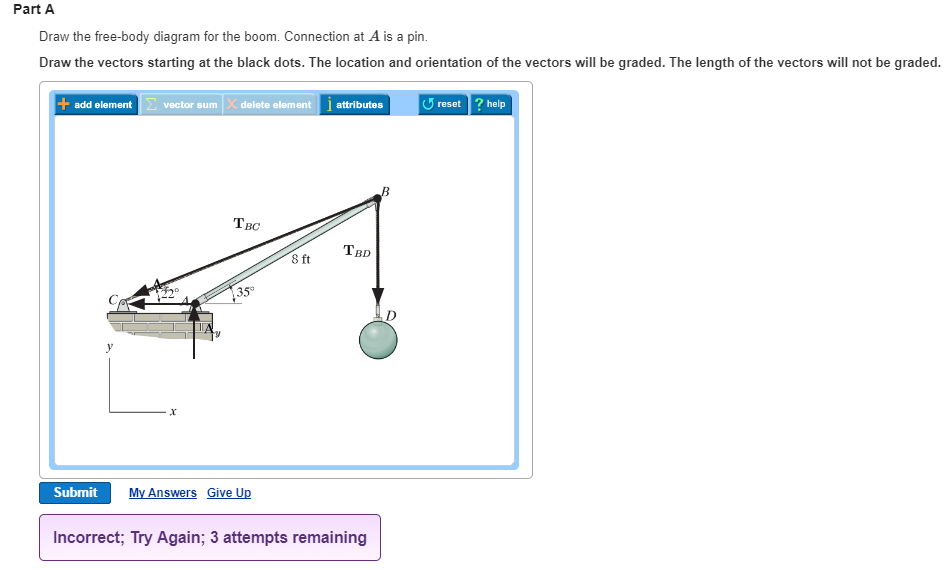
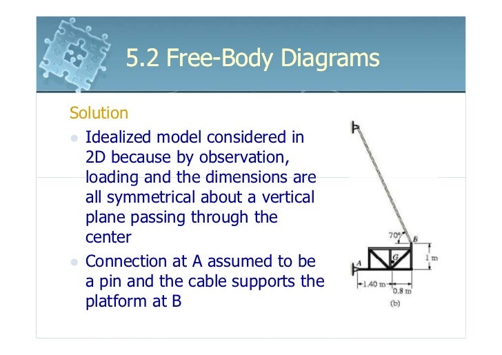
Draw the free-body diagram for the boom. Connection at A is a pin. Draw the vectors starting at the black dots. The location and orientation of the vectors will be graded. The length of the vectors will not be graded. The dimensions of a jib crane, which is manufactured by the Basick Co., are given in the figure.
Question: Draw the free-body diagram for the boom. Connection at A is a pin. Draw the vectors starting at the black dots. The location and orientation of the vectors will be graded. The length of the vectors will not be graded. The dimensions of a jib crane, which is manufactured by the Basick Co., are given in the figure.
A is a rocker and B is a pin. Draw the vectors starting at the black dots. The location and orientation of the vectors will be graded. The length of the vectors ...

May 13, 2017 — Draw the free body diagram for the boom connection at a is a pin. My free body shows a collinear force t through the rope the given downward ...

Body Incomplete FBD 1. Bell crank supporting mass m with pin support at A. 2. Control lever applying torque to shaft at 0. 3. Boom 0A, of negligible mass compared with males in. Boom hinged at 0 and supported by hoisting cable at B. 4. Uniform crate of 111355 In leaning agamst smooth venicaLwall and supported on a rough horizontal surface. 5.
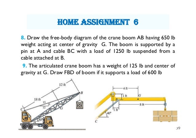
8. Draw the free-body diagram of the crane boom AB having 650 lb weight acting at center of gravity G. The boom is supported by a pin at A and cable BC with a load of 1250 lb suspended from a cable attached at B. 9.

Free-Body Diagram: First PROBLEM 4.121 The assembly shown is to collar A that fits the vertical pin shown, The pin can couples about x and t. axes but does prevent or along the For the loading shown, determine the tension in each cable and the reaction at A. 08 (0.08)2 N -e 0.6j) 12 —0.6k) T = 200N N (a) 480 N -O -480 N From D. Of assembly:
1. If the support reactions are not given, draw a FBD of the entire truss and determine all the support reactions using the equations of equilibrium. 2. Draw the free-body diagram of a joint with one or two unknowns. Assume that all unknown member forces . act in tension (pulling the pin) unless you can determine

4.2 Free Body Diagrams The free body diagram is a depiction of an object or a body along with allthe external forces acting on it. • Choose and draw the body (with dimensions). Carefully define its boundaries. • Imagine the body in its current state and how it interacts with its surroundings. • Draw ALL the external forces acting on the ...

The above diagrams, which show the complete system of applied and reactive forces acting on a body, are called free body diagrams. The whole system of applied and reactive forces acting on a body must be in a state of equilibrium. Free-body diagrams are, consequently ,often called equilibrium diagrams. Drawing equilibrium diagrams and finding
.PNG)
To draw a free body diagram, start by sketching a simple representation of the body you want to make the diagram of, like a square to represent a box. Next, draw arrows on the shape that show the forces acting on the object. For example, draw a downward arrow to signify the weight of the object, since gravity pulls the object down.

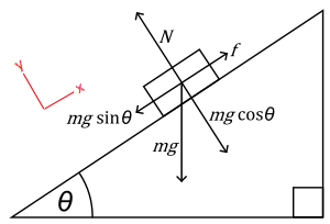
Engineering Mechanics - Statics Chapter 5 Problem 5-1 Draw the free-body diagram of the sphere of weight W resting between the smooth inclined planes. Explain the significance of each force on the diagram. Given: W = 10 lb θ 1 = 105 deg θ 2 = 45 deg Solution: NA, NB force of plane on sphere. W force of gravity on sphere.
FREE-BODY DIAGRAMS (Section 5.2) 2. Show all the external forces and couple moments. These typically include: a) applied loads, b) support reactions, and, c) the weight of the body. Idealized model Free-body diagram (FBD) 1. Draw an outlined shape. Imagine the body to be isolated or cut "free" from its constraints and draw its outlined shape.
16. We can now draw a free-body diagram of pin B: B 2121 N 3000 N 1500 N 1500 N 45˚ 17. Checking for static equilibrium at pin B gives: x!F = 2121 cos 45˚ - 1500 = 0 y!F = 1500 + 2121 sin 45˚ - 3000 = 0 18. We can also draw a free-body diagram for pin C: C 2121 N 1500 N 1500 N 45˚
5.4 Draw a free body diagram of the automobile side mirror pictured, by ... Calculate the reaction forces at the pin at point A and the roller at point B.126 pages
37 Free Body Diagrams Wednesday, October 3, 2012 New Support Conditions Pin Connection ! Another way Here is a pin support 38 Free Body Diagrams Wednesday, October 3, 2012 New Support Conditions Pin Connection ! On a pin, we know that there is an x and a y component of the reaction but without other

Engineering Mechanics - Statics Chapter 5 Problem 5-10 Draw the free-body diagram of the beam, which is pin-connected at A and rocker-supported at B. Given: F = 500 N M = 800 N⋅ m a = 8m b = 4m c = 5m Solution: Problem 5-11 The sphere of weight W rests between the smooth inclined planes. Determine the reaactions at the supports.


0 Response to "39 draw the free-body diagram for the boom. connection at a is a pin."
Post a Comment