39 ray diagram for diverging lens
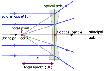
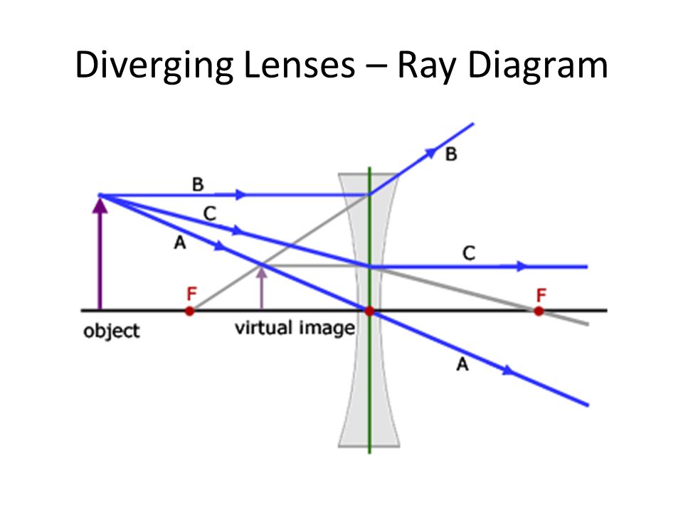
A diverging lens ray diagram follows three basic rules: Any ray of light that is parallel to the principal axis of the lens will pass through its focal point after refraction. Any incident ray of light that passes through the focus of the lens before getting refracted will emerge parallel to the principal axis on refraction. Constructing Ray Diagrams. For each of these applets, use the GeoGebra tools to construct where the image will appear. Then, use the measure tool to find its height, and calculate the magnification of this lens. You should also SALT your image. Type your answer here…. Find the height of the image, and hence the magnification.
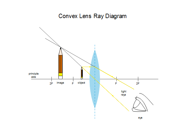
Two Converging Lens Ray Diagram. Examples are given for converging and diverging lenses and for the cases where the The third ray is not really needed, since the first two locate the image. In this section of Lesson 5, we will investigate the method for drawing ray diagrams for objects placed at various locations in front of a double convex lens.
Ray diagram for diverging lens
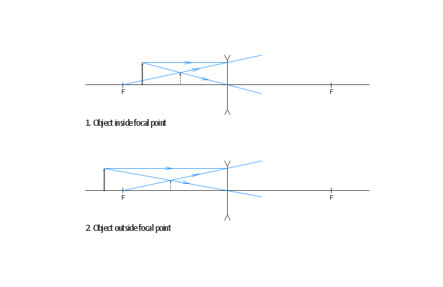
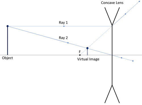
14+ Diverging Lens Ray Diagram. Examples are given for converging and diverging lenses and for the cases where the object is inside and outside the principal focal length. Ray tracing for concave or diverging lens draw different ray diagrams with the object at different places in relation to the focus and find out where the image appears. Ray Diagrams for Lenses. The image formed by a single lens can be located and sized with three principal rays. Examples are given for converging and diverging lenses and for the cases where the object is inside and outside the principal focal length. The "three principal rays" which are used for visualizing the image location and size are: Ray 1 is parallel to the axis and refracts as if from F. Ray 2 heads towards F' before refracting parallel to the axis. Ray 3 passes straight through the center of the lens. image is always virtual, upright and reduced O F I F' Ray diagram for diverging lens
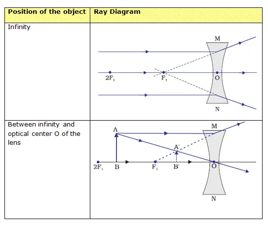
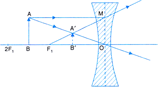
Ray diagram for diverging lens. We draw another ray which passes through Optical Center So, the ray will go through without any deviation We observe that both refracted rays are diverging It means that they would have met at some point Hence, we extend both rays behind the lens We see that the rays form an image behind the lens (on the left side). So, the image is virtual Earlier in Lesson 5, we learned how light is refracted by double concave lens in a manner that a virtual image is formed.We also learned about three simple rules of refraction for double concave lenses: . Any incident ray traveling parallel to the principal axis of a diverging lens will refract through the lens and travel in line with the focal point (i.e., in a direction such that its ... Converging and diverging lenses ray diagrams worksheet answers. Objective: The objective is to verify the formula of thin lenses by forming the image of an object in a convergent lens (convex). Equipment: A lens support, a converging lens (convex), an optical counter, a lampholder, a low watt bulb, a rectangular target, a lens support, and a ... Ray diagrams for diverging (concave) lens. If an object is on one side of the concave lens, the concave lens can form the image of the object. If the position of the object on one side of the concave lens is known, how to draw the image formation of the object? Suppose an object is on the left side of the concave lens as shown in the figure below.
Using the lens equations, calculate to verify the characteristics of the images, for the diverging lens as shown in the ray diagram. Fit your answer on the provided spaces below. 2.1. d i =. 2.2. m =. 2.3. h i =. The top diagram shows the formation of the virtual object where converging rays are prevented from meeting by the diverging lens. Then those converging rays are made to diverge by the lens and so a virtual image is formed. Update as a result of a comment from @Floris. Here you have the ray diagrams used to find the image position for a diverging lens. A diverging lens always form an upright virtual image. Ray diagrams are constructed by taking the path of two distinct rays from a single point on the object: A ray passing through the center of the lens will be undeflected. A ray proceeding parallel to the principal axis will diverge as if he came from the ... The ray diagram constructed earlier for a diverging lens revealed that the image of the object was virtual, upright, reduced in size and located on the same side. Any incident ray traveling parallel to the principal axis of a diverging lens will refract through the lens and travel in line with the focal point (i.e., in a direction such.
To explain how to draw the diagrams, there are two key things to remember. 1 A converging lens refracts the light so that any ray of light parallel to the principal axis (the thick horizontal line) is turned to pass through the focal point. Rays of light parallel to the principal axis are all refracted through the focal point. This Demonstration lets you visualize the ray diagrams for converging and diverging lenses. By manipulating the object and lens locations, you can create real or virtual images. The rays parallel to the principal axis and the ray through the center of the lens are drawn.Locators allow you to drag both the object and the lens. You can change the focal length using a slider. Diverging lens. Author: Ray Tuck. This simulation shows a ray diagram for a diverging lens. Use the slider to set the position of the object. The object is shown by a black arrow. Use the check boxes to choose which rays to show. You need any two to fix the position of the image. The image is shown by the red arrow. 122 - Ray Diagrams - LensesIn this video Paul Andersen explains how ray diagrams for lenses can be used to determine the size and location of a refracted ima...
Diverging lenses ray diagrams. While diverging lenses constantly produce virtual pictures converging lenses are capable of creating both real and also virtual images. The image allude of the top of the thing is the allude where the 3 refracted light ray intersect. Ray diagram because that object situated in former of the focal distance point. 1 ...
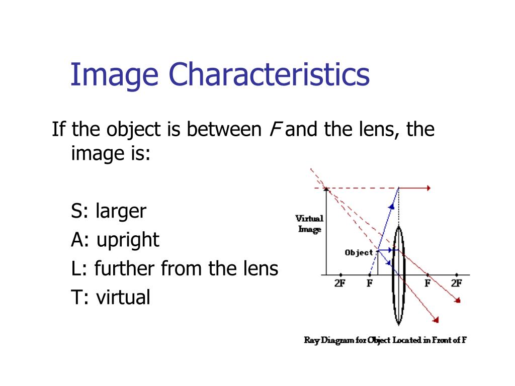
Ray Diagram for Object Located in Front of the Focal Point. In the three cases described above - the case of the object being located beyond 2F, the case of the object being located at 2F, and the case of the object being located between 2F and F - light rays are converging to a point after refracting through the lens. In such cases, a real image is formed.
Diverging Lenses As such, the rules for how light behaves when going through a diverging lens is a little bit different. You will be expected to be able to draw a Ray Diagram of a converging and diverging lens on our upcoming test without the rules.
Real images occur when objects are placed outside the focal length of a converging lens (s>f). If the lens is converging but the distance from the object to the lens is smaller than the focal length, the image will be virtual. Diverging lenses always produce virtual images. This calculator shows a ray diagram when the image is real. Magnification
Convex lens forms real image because of positive focal length and concave lens forms virtual image because of negative focal length. In mirrors , images are formed through reflection but lens es form images through refraction . This is explained with the help of ray diagram s as follows 1. Introduction (Refraction and Lens es) 2. The Lens Equation 3. Concave Lens es 4.
The ray diagram constructed earlier for a diverging lens revealed that the image of the object was virtual, upright, reduced in size and located on the same side. Any incident ray traveling parallel to the principal axis of a diverging lens will refract through the lens and travel in line with the focal point (i.e., in a direction such.
A convex lens is thicker in the middle than it is at the edges. Parallel light rays that enter the lens converge. They come together at a point called the principal focus. In a ray diagram, a ...
View Notes - Diverging Lenses - Ray Diagrams from GEO 111 at Vilniaus Gedimino technikos universitetas. 3/6/2011 Diverging Lenses - Ray Diagrams h om e - a bout - te rm s - cre dits - fe e dback T
Thus we imagine a diverging lens put between C and I in figure 1 interrupting the rays to the image , so that it becomes a virtual object for the second lens. The virtual object and virtual rays Fig.4 Ray diagram for diverging lens: virtual object, real image.
Description of how to draw ray diagrams for diverging lenses for grade 10 science.
Rules to Draw a Ray Diagram of Diverging Lenses. Essential rules to be remembered while drawing a ray diagram for a diverging lens are as follows. When a ray of light: · Is parallel to the principal axis, then the refraction from the lens causes the rays to pass through the focus of the lens.
Ray 1 is parallel to the axis and refracts as if from F. Ray 2 heads towards F' before refracting parallel to the axis. Ray 3 passes straight through the center of the lens. image is always virtual, upright and reduced O F I F' Ray diagram for diverging lens
Ray Diagrams for Lenses. The image formed by a single lens can be located and sized with three principal rays. Examples are given for converging and diverging lenses and for the cases where the object is inside and outside the principal focal length. The "three principal rays" which are used for visualizing the image location and size are:
14+ Diverging Lens Ray Diagram. Examples are given for converging and diverging lenses and for the cases where the object is inside and outside the principal focal length. Ray tracing for concave or diverging lens draw different ray diagrams with the object at different places in relation to the focus and find out where the image appears.

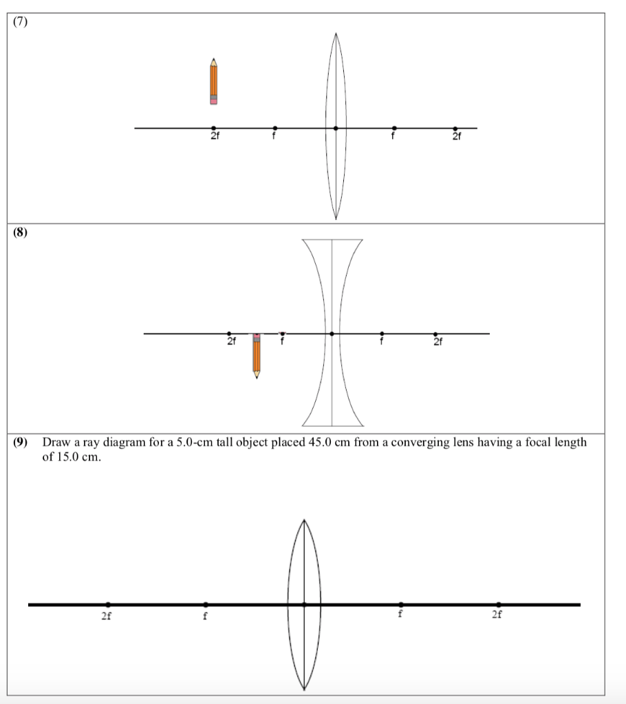
Converging Diverging Lenses Ray Diagrams Directions Use At Least Two 2 Rays With Different Colors Homeworklib
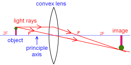
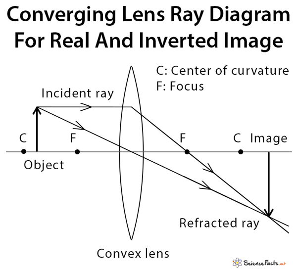
Gcse Physics Ray Diagram For An Image Made By A Convex Lens What Is A Real Image What Is An Inverted Image Gcse Science

Show By A Ray Diagram That A Diverging Lens Cannot Form A Real Image Of An Object Placed Anywhere On Its Principal Axis Physics Shaalaa Com












0 Response to "39 ray diagram for diverging lens"
Post a Comment