35 copeland potential relay wiring diagram
Potential Relay Wiring Diagram - compressor potential relay wiring diagram, copeland potential relay wiring diagram, mars potential relay wiring diagram, Every electrical arrangement consists of various distinct components. Each part should be set and connected with different parts in particular way. If not, the structure won't function as it ...
MARS HVAC Potential Relays MARS series relays are manufactured for the HVAC industry. These relays meet all requirements for original equipment relays. Features: • 50/60 Hz • cULus • Contact rating 35 amp, 400 VAC • Operating position tab up • Instructions and wiring diagram included in each relay • Class "B" insulation C O M P ...
Copeland Potential Relay Wiring Diagram Run Capicator For Hard Start Wiring Diagram Wiring Diagrams All Danfoss Current Relay Wiring DIAGRAM] 240v Airpressor Wiring Diagram FULL Version HD An automobile run relay adjust in size from the 3-pin to 5-pin types. The 4-pin type is generally used throughout the automobile.

Copeland potential relay wiring diagram
Potential relay /940-0140-03 I did some research and found these xref numbers: Start Capacitor Wholesaler P/N 914-0053-14 Copeland P/N 014-0053-30 Potential Relay Wholesaler P/N 940-0140-03 Copeland P/N 040-0166-02 GE P/N 3ARR3T25S5 The unit already had a potential relay installed.
Copeland start/run/potential relay question. Swapped compressor today in a Carrier 3-ton rooftop, with the comp. supplier gave me a 35Uf cap, a 178Uf "start cap" & a potential relay, original compressor just had L1 to Common, L2 to Run & 40Uf cap to Start terminals, no diagrams & no Copland website literature, supplier sent me only thing ...
12+ Copeland Compressor Wiring Diagram Single Phase. Single phase cr6/5t bristol tecumseh carlyle danfoss zrk5/k3/kc legend voltage code h20b153abc. Fancy single phase pressor wiring diagram with relay elaboration from wiring diagram for copeland compressor , source:itseo.info repair parts for the campbell hausfeld model wl thanks for visiting our website, contentabove…
Copeland potential relay wiring diagram.
potential relay wiring diagram - You will need a comprehensive, expert, and easy to understand Wiring Diagram. With such an illustrative guide, you'll be capable of troubleshoot, avoid, and total your projects easily. Not just will it assist you to accomplish your desired outcomes faster, but additionally make the complete procedure easier for everyone.
Copeland Potential Relay Wiring Diagram Run Capicator For A run relay helps to prevent wires from overloading and overheating. Overheated wires can spark a fire. They pull off not prevent volt spikes. If a relay switch stops vigorous for some reason, it is practical to exam it. This is unquestionably applicable in automobiles, as one switch can ...
Del City offers a full range of electrical supplies including wire, cable, electrical terminals, connectors, relays, circuit breakers, electrical wire, fuses, switches, and loom for automotive, truck, trailer, marine and other OEM/MRO applications.
Compressor Potential Relay Wiring Diagram - One of the most hard automotive repair tasks that a mechanic or fix shop can give a positive response is the wiring, or rewiring of a car's electrical system.The hardship in reality is that all car is different. subsequent to a pain to remove, replace or repair the wiring in an automobile, having an accurate and detailed compressor potential ...
A relay is an electrically operated switch. Learn how to wire a 4 or 5 pin relay with our wiring diagrams and understand how relays work.
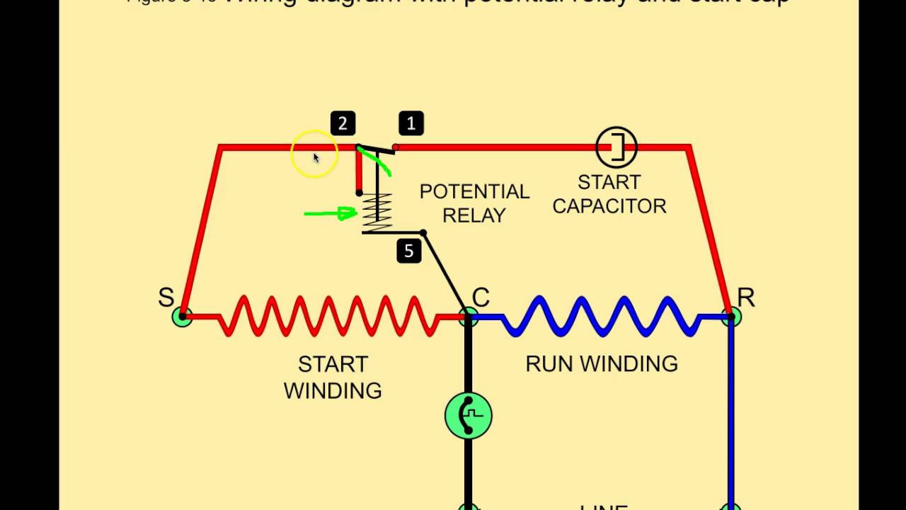
winding with start and run capacitor and potential relay. A Over current thermal protection switch in the terminal box for single-phase ... DWM Copeland semi-hermetic compressors are available for 50 and/or 60 Hz voltage supply. The use of a ... accordance with the position of the capacitors and relay shown on the wiring diagram.
Quick and easy way to wire a relay to safely power added lights. Why you need a relay is also covered. This video will explain details of how to wire a relay...
In the rubber plug that plugs into the compressor, there is a rectifier that changes the voltage DC. Do NOT put 24vlts AC to the solenoid. This will burn up the coil. (COPELAND K1 SCROLL COMPRESSOR ONLY) 1 Fig. 6—MH1A- (A) Heat Pump Schematic Diagram and Electric Heater Wiring Options v, 1 Phase, 60 Hertz A 5KW 5KW 5KW TOP 2 BANKS NOTES ...
November 5, 2020 - A simple 5 pin relay wiring diagram and how to use SPDT relay in circuits, how to use relay with fly back diode with a transistor or microcontroller.
Copeland Potential Relay 040 0166 19 Wiring | Wiring Diagram - Potential Relay Wiring Diagram. You are able to often depend on Wiring Diagram as an important reference that may assist you to preserve money and time. With the assist of this e-book, you'll be able to very easily do your own personal wiring tasks.
HVAC Training Solutions, LLCSummerville, SChttps://www.hvactrainingsolutions.net904-742-9511We provide online HVAC Training. We are an online HVAC School wer...
If you are looking for copeland potential relay 040 0166 19 wiring you have come to the perfect site. Instructions for wiring a standard automotive relay with descriptions of the pin out and the schematic. This is the wiring of the potential relay. Ribu1c wiring diagram lovely generous potential relay wiring diagram.
Know your potential starting relays | achr news
September 29, 2021 - In this powerful article, you are going to quickly learn the skill of wiring a car relay by yourself without an expert with practical demonstration of wiring the four-pin car relay for horn and lights.

55 new potential relay wiring diagram- a govern relay is used ...
A/C Copeland Scroll® .. Compressor wiring diagrams with motor winding connec- Data-Copeland Scroll Compressors, and Electrical. Refer to original equipment wiring diagrams. Care must be taken to ensure that wiring or . The Copeland Scroll compressor's inherent. Copeland Scroll compressors have a voltage tolerance of + 10%.

Air condition compressor potential relay wiring - eee community
Your Audio Solutions HQ Since 1986. Shop 18,000+ Audio Parts from Speakers and Subwoofers to Home Theater and Pro Audio. Top Gear at Low Prices and FREE Shipping

Pin on bad ass tools
Electrical wiring diagram tfd 3 phase. Universal bracket allows using the existing mounting of the potential relay being replaced. Copeland outdoor condensing unit. The purpose of this booklet is to dem onstrate how to wire a. Replaces both 3 and 5 terminal potential relays supr has dimensions identical to the industry standard potential relay.

10.3 potential relays - 10.4 solid-state starting relays and ...
May 11, 2018 - Best Relay Wiring Diagram 5 Pin Wiring Diagram Bosch 5 Pin Relay ...

P&m potential relay - model pm-a3c2 - hvac, air conditioning ...
This is the wiring of the potential relay. This video is part of the heating and cooling series of training videos made to accompany my websites: www.grayco...

Potential relays - what happened to terminal 3? | hvac
March 27, 2019 - I have spent most of my career being afraid of hard start kits, I heard too many horror stories of start caps exploding and sales technicians telling every customer they need one. It dawned on me recently that it may be time for me to take a more mature look at start capacitors, potential relays, ...

Electrical and electronics engineering: air condition ...
Javascript is disabled in this browser. This page requires Javascript. Modify your browser's settings to allow Javascript to execute. See your browser's documentation for specific instructions · Are you sure you want to switch accounts · Switching accounts in the middle of an order will clear ...
Potential relays - commercial refrigeration online hvac training
May 12, 2019 - I am trying to wire a potential relay into my rotary Phase Converter for remote starting. I am not having success. Here is the wiring diagram that I f

10.3 potential relays - 10.4 solid-state starting relays and ...
China Copeland Scroll Compressor Wiring Diagram Zr125kc E Tf5 522 Manual Zr. 4 Copeland Semi Hermetic Compressor Product Catalogue Feb 2010 By Andrew Tan Lee Issuu. Copeland semi hermetic compressors 4 compressor wiring diagram for open thermal overload on scroll c sbs235h38b china emerson electronics bush of herm discus technical information ...

Diagram of the potential relay part 2
6 Feb 2008 — A/C Copeland Scroll® ... Current and potential relays are used to actuate com- ... Electrical Handbook wiring diagrams show the compres-.543 pages

Unique single phase capacitor start capacitor run motor ...
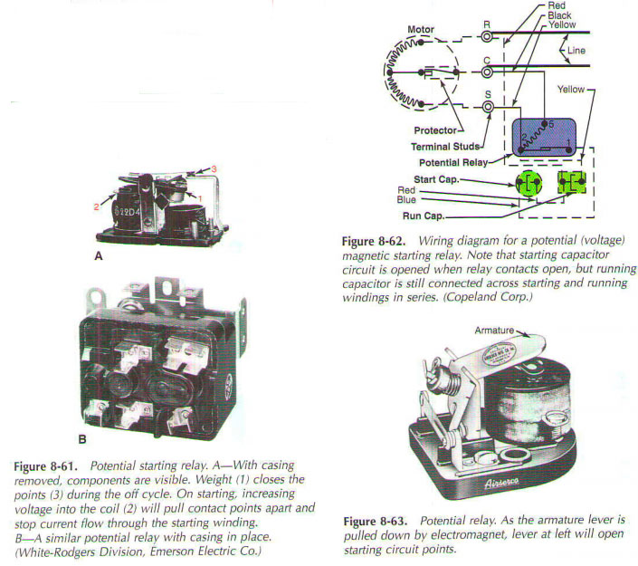
March 5, 2018 - Potential relays are commonly found on many smaller, single-phase, capacitor-start, capacitor-run motors in the HVACR industry. Their function is to assist in starting the electric motor. Potential relays are sometimes referred to as voltage relays because they rely on the back-electromotive-force ...
![como vestir a los 50 años hombres: [Get 42+] Ac Compressor ...](https://static-assets.imageservice.cloud/1116375/relay-ac-unit-diagram-as-well-hard-start-capacitor-wiring-diagram-on.jpg)
Como vestir a los 50 años hombres: [get 42+] ac compressor ...
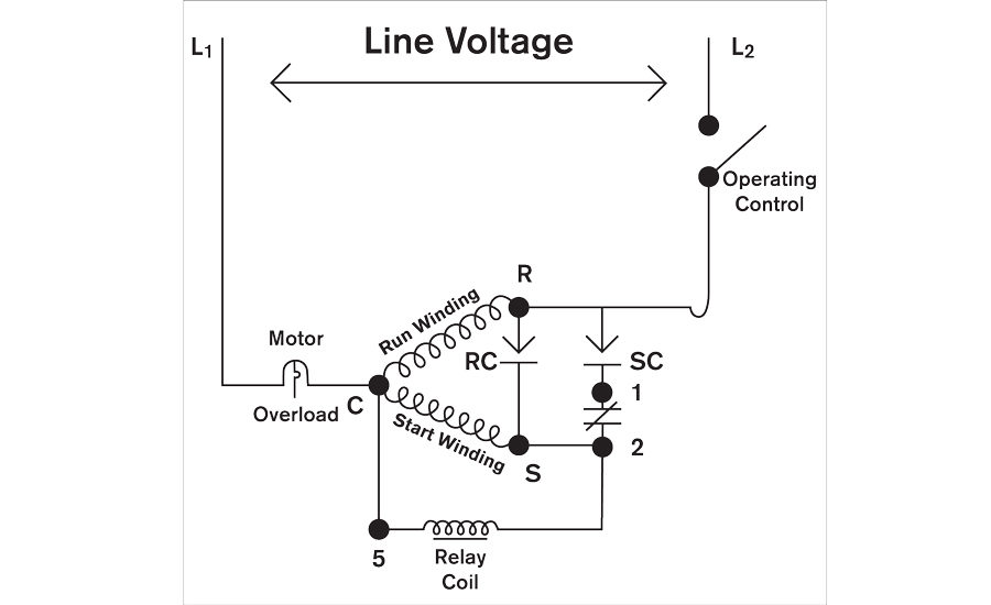
3-wire hard start schematic. Start winding. Run Winding. Potential. Relay ... RectorSeal 2019. Copeland handbook has 64 Potential. Relays! COPELAND.
![WRG 8228] Potential Relay Wiring Diagram | Hvac air ...](https://i.pinimg.com/564x/73/ab/e6/73abe674629c0c5126dd4aca577bad05.jpg)
Wrg 8228] potential relay wiring diagram | hvac air ...
They are usually labeled and identified on the fuse bin panel. Copeland Condenser Schematic Wiring Diagrams BlogCopeland Potential Relay Wiring Diagram Run ...
Electrical handbook
Explaining the differences between current relays and potential relays and their role in starting compressors.
Electrical handbook
They are usually labeled and identified on the fuse bin panel. Copeland Condenser Schematic Wiring Diagrams BlogCopeland Potential Relay Wiring Diagram Run ...

Basic electrical controls of air-conditioning units ...
10.3 Potential Relays - 10.4 Solid-State Starting Relays and Devices - 10.5 Motor Bearings - 10.6 Motor Drives (Components for Electric Motors)
![Copeland Electrical Handbook - [PDF Document]](https://reader021.docslide.net/reader021/html5/20170803/55cf9b5c550346d033a5c516/bg3.png)
Copeland electrical handbook - [pdf document]
September 2, 2002 - Potential or “voltage” relays are used with single-phase capacitor-start/capacitor-run motors, which need relatively high starting torque. Their main function is to assist in starting the motor. Knowing the sequence of operation for this type of starting relay can help you diagnose, confirm, ...

Potential for good and evil (the hard start & potential relay ...
Copeland Potential Relay Wiring Diagram Run Capicator For Electrical Switch Wiring, 3 Way Switch Wiring. 55 New Potential Relay Wiring Diagram.

Copeland electrical handbook | pdf
January 2, 2021 - Potential relays also known as voltage relays are used in capacitor-start capacitor-run (CSR) motors. We provide online HVAC Training.
Symptom-cause troubleshooting | achr news
Our Book https://www.acservicetech.com/the-book In This HVACR Training Video, I go over How the Potential Relay Works and How to Troubleshoot it! I show the ...
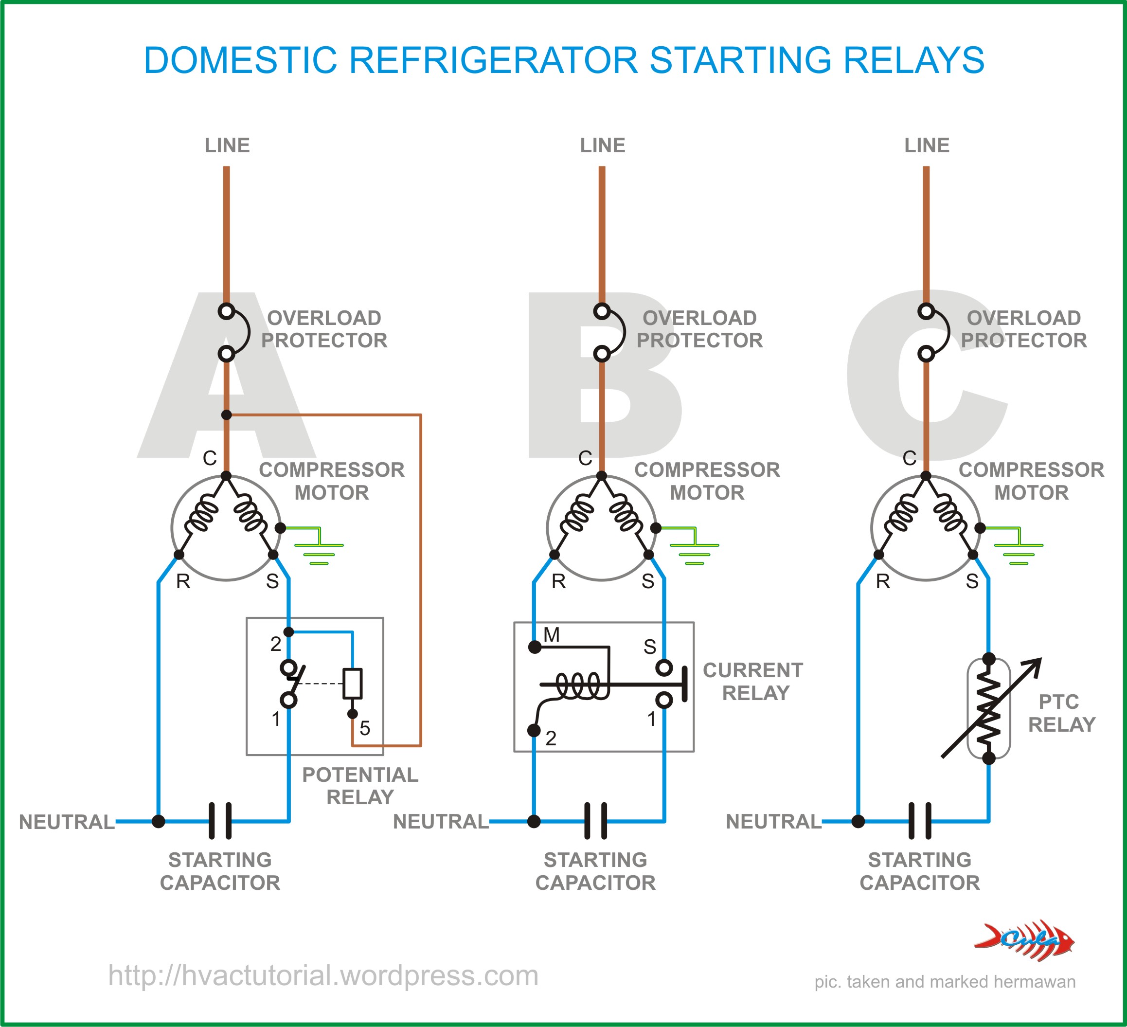
Domestic refrigerator starting relays | hermawan's blog ...
Wholesaler Copeland® GE P/N Pick-up Drop Out Cont. Volt Freq. P/N Brand P/N Volts Volts Rating Potential Relay Data 940-0001-82 040-0166-39 3ARR3T3U5 220 - 240 40 - 90 332 60
E 2 motors and motor starting 2 compressor
The Digital Compressor Controller is designed only for single phase Copeland Scroll . Copeland compressor wiring together with copeland potential relay wiring diagram furthermore what is a hermetic motor pressor also lincoln mig welder parts diagram along with b backhoe wiring diagram together with us moreover tecumseh pressor wiring diagram ...
Motors for copeland™ semi-hermetic compressors
A – Hermetic Compressors Emerson Climate Technologies 2014DS-78 R2 (2/16)4 AF - Compressor Parts Model Start Capacitor Run Capacitor Current Relay Potential Relay Overload
Electrical handbook
They are usually labeled and identified on the fuse bin panel. Copeland Condenser Schematic Wiring Diagrams BlogCopeland Potential Relay Wiring Diagram Run ...
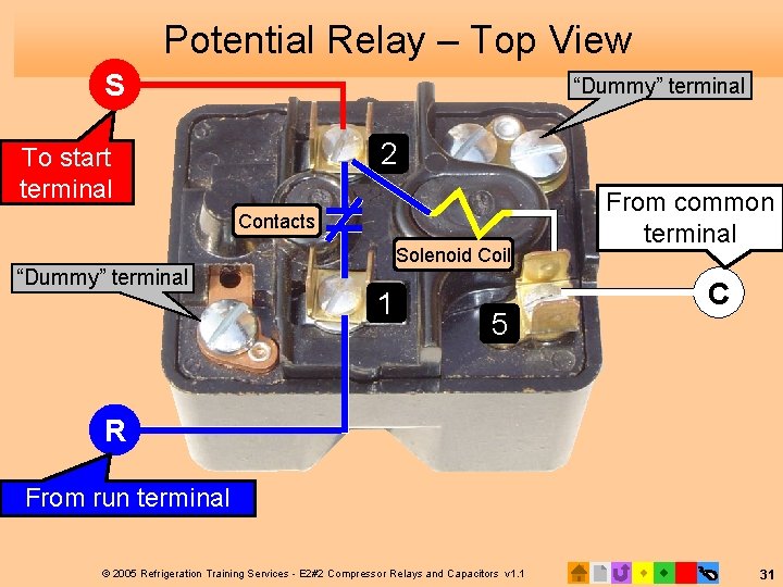
Potential (magnetic) relay: potential relay and current relay ...
As taking into account any electrical wiring make determined all wire friends are made securely bearing in mind the proper size wire nuts that they are not aimless and Potential Relay Wiring Diagram compressor potential relay wiring diagram copeland potential relay wiring diagram mars potential ...
Motors for copeland™ semi-hermetic compressors
55 New Potential Relay Wiring Diagram- A govern relay is used in the automotive industry to restrict and regulate the flow of electricity to various electrical parts inside the automobile. They permit a small circuit to direct a later flow circuit using an electromagnet to rule the flow of electricity inside the circuit.
Potential relays
Copeland Potential Relay 040 0166 19 Wiring | Wiring Diagram – Potential Relay Wiring Diagram. You are able to often depend on Wiring Diagram as an important reference that may assist you to preserve money and time. With the assist of this e-book, you’ll be able to very easily do your own personal wiring tasks.
Universal comp potential relay 2-5hp 1ph
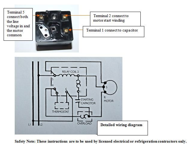
Copeland Compressor Wiring Diagram. accordance with the position of the capacitors and relay shown on the wiring diagram. Compressor model. Run capacitor. Start capacitor. Potential relay. MISWIRING IS MURDER. It is very easy to miswire a compressor, but the results can be deadly. The purpose of this booklet is to dem- onstrate how to wire a.
Operating and troubleshooting potential or voltage relays ...
Copeland Potential Relay Wiring Diagram. Know your potential starting relays achr news 10 3 4 solid state and devices 5 motor bearings 6 drives components for electric motors p m relay model pm a3c2 hvac air conditioning spare parts suppliers wholers in dubai good evil the hard start school electrical handbook copeland pdf doent basic controls ...

Domestic refrigerator starting relays | hermawan's blog ...
Copeland Potential Relay Wiring Diagram. Print the electrical wiring diagram off plus use highlighters in order to trace the routine. When you make use of your finger or perhaps stick to the circuit together with your eyes, it is easy to mistrace the circuit. 1 trick that I use is to print exactly the same wiring picture off twice.

Copeland potential relay 040-0001-02 040-0001-11 | ebay
Potential Relay Wiring Diagram – compressor potential relay wiring diagram, copeland potential relay wiring diagram, mars potential relay wiring diagram, Every electrical arrangement consists of various distinct components. Each part should be set and connected with different parts in particular way. If not, the structure won’t function as it should be.
Motors for copeland™ semi-hermetic compressors
Copeland Potential Relay Wiring Diagram. Copeland potential relay wiring diagram hermetic compressor voltage relays capacitor chart tifom what happened to elect handbook start a cscr motor electrical single phase wire diagrams 45 beautiful danfoss. Diagram Copeland Potential Relay Wiring Run Capicator For Full Version Hd Quality Diagramia ...
Final2_online version_a4 cdu catalogue_20pp
55 New Potential Relay Wiring Diagram- A govern relay is used in the automotive industry to restrict and regulate the flow of electricity to various electrical parts inside the automobile. They permit a small circuit to direct a later flow circuit using an electromagnet to rule the flow of electricity inside the circuit. ... Copeland Condenser ...
0 Response to "35 copeland potential relay wiring diagram"
Post a Comment