36 aerator timer wiring diagram
Diagram Boat Aerator Wiring Diagram Full Version Hd Quality Wiring Diagram Nervoussystemdiagram Conservatoire Chanterie Fr . It shows the elements of the circuit as simplified shapes and also the power as well as signal links in between the gadgets. John deere aercore 800 wiring diagram. All information illustrations and specifications in this ... Strip 1 2 inch of the covering from each insulated wire entering the intermatic timer with wire strippers. Variety of intermatic st01 wiring diagram. Each wire set contains two insulated and one bare wire. Wire c jumper diagram 2. Strip the existing wire ends 7 16 to 7 16. An example of single pole and three way wiring follow.
Doent Doent Baxi 630 Combi Wiring Diagram Heating Spare Parts Baxi Platinum Combi 33 HE Manuals and User Guides, Boiler . Duo-tec Combi Installation and Service Manual Gas Fired Wall Mounted Condensing Combination Boiler 24 - 28 - 33 - 40 28 LPG en United Kingdom These instructions include the Benchmark Commissioning Checklist and should be ...

Aerator timer wiring diagram
01.05.2017 · If your riding mower keeps blowing fuses, learn how to troubleshoot the possible causes. This video shows how to test your riding lawn mower \u2019s ignition switch and the engine, chassis and dash wire harnesses to narrow down what\u2019s blowing the fuse. Craftsman Lt Riding Lawn Mower Manual Find part in diagram CRAFTSMAN Lawn, Tractor Model # This model has a separate ... 4 way switch diagram. One ground and 4 circuit terminals divided into two matching pairs called travelers. In this circuit the power comes in through the first switch. Two switches will be 3-way and one will be a 4-way. In the diagrams below the first switch 3-way common terminal connects to line voltage. Aug 11, 2010 · 3 posts · 1 authorI made a rough wiring schematic of the way I would like to wire up my aerators and attached it. My boat has 2 fresh water aerators and 2 ...
Aerator timer wiring diagram. Boat Ignition Switch 6 Wire. May 16, 2021. Solder it to the B terminal with silver core solder and a soldering iron. Key Switch Ignition 6 Wire Mercury 2895 Sea Dog Line - 30044272 Sea Dog 420488-1 Kill Switch with Lanyard 1250 781 1 oz Sierra International MP41000 Ignition Switch white 2625 Compare with other electronic switches. Create a visual plot diagram of "The Devil and Tom Walker".Separate the story into the Exposition, Conflict, Rising Action, Climax, Falling Action, and Resolution. Create an image that represents an important moment or set of events for each of the story components. Write a description of each of the steps in the plot diagram. The devil and tom walker plot diagram example exposition. READ Aerator Timer Wiring Diagram Database. Camaro Wiring Diagram Source: sinusdiagram.biennaleangelogarofalo.it Camaro Wiring Diagram Source: image.jimcdn.com. Facebook Tweet Pin. MUST-KNOW TIPS FOR DIY ELECTRICAL WIRING AND CHANGING 1. Have the right tools handy. The nuts that hold the bracket can be stubborn so use some WD-40 or some other anti-rust spray. Determine the problem with your hornStep 2. 1 Locate the horn which looks like a small metal disk with two cables joined to it. How to Fix Car Horn - YouTube.
The following requirements on wire color codes apply in Canada. BLACK OR RED HOT. Provide over-current protection of 15 amperes for general purpose wiring lights and receptacles. The AC power cable color code is nearly similar to the code used in the USA except exclusion of bare copper from ground wire. Wiring diagrams attached. Note these are labeled for CC boats, not DC, but the harness is the same for both models. 15-17-19 wiring diagrams- 2000.pdf (114.92 KiB) 0 Johnson Boat Livewell Aerator Pump 3810 19/05/2016 · I want to install a livewell timer switch. My current setup has the livewell pump and the bilge pump on the same switch. Up for livewell … Johnson Pump Livewell Aerator Pump Rule 403STC Literature Download Owners Manual. port base for. threaded port for washdown installation. optional washdown Multicore Cable Unscreened 2 Core 041 mm² 328 ft 100 m. Cobra 13mm X 5m Black Cable Management Heavy. 3 Core Armoured SWA - 15mm - 25mm - 4mm - 6mm - 10mm - 16mm - 25mm. 6mm 3 Core Armoured Cable is a type of electrical cable used to supply mains voltage electricity for a variety of uses.
115. Loc. Reading PA. Oct 31, 2021. #35. jet pump on floor feeds blue pressure tank. From there it goes into the skinny vertical white tank, which is your water softener. Some form of resin in the tank, looks like very small beads, brownish in color. Black brine tank connects at back. 2 Tools you will need: 3 Diagram and Parts List. 4 Faucet Dimension. 4.1 Step 1: Remove washers and mounting nut. 4.2 Step 2: Installing the faucet. 4.3 Step 3: Connect waterlines to main valve. 4.4 Step 4: Install Press pop-up assembly. 4.5 Step 4: Install Press pop-up assembly. 4.6 Step 5: Flush faucet. Rheem Water Heater Manuals. It can sometimes be difficult to find the correct instruction manual for your device, particularly for older, discontinued models. Use the search bar below to find your specific Rheem Water Heater Manual. You can enter the model number, name or description. We've also included images to help. Dec 28, 2012 — I am kinda intrested if the rotary timer switch is a timer or a selector switch that controls the timer. any details or wiring diagrams on the ...

The aerator on my sewer system is reading aerator locked/short , but it is not locked and does not gave a short. On 2019-07-05 by Anonymous. causes for high water to be in chlorinator of a aqua klear septic tank. Alarm going off and sprinklers not spraying. Any assistance would be appreciated. On 2019-06-03 by (mod) - well pump lost prime
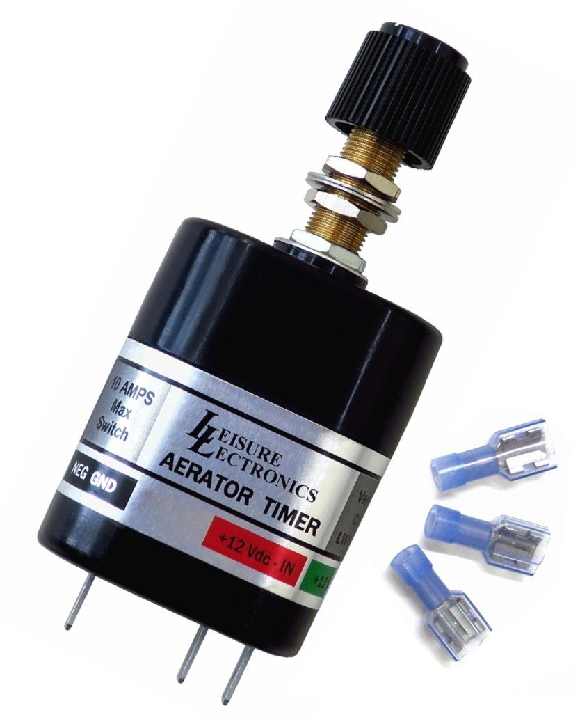
Find many great new & used options and get the best deals for VARIABLE / ADJUSTABLE AERATOR FISH LIVEWELL TIMER SWITCH,12 VOLT, BOAT, LWS-V at the best online prices at eBay! Free shipping for many products!

I have a 1999 champion and the hydro rocker switch is faulty. the original switch is a carlincswitch 5 pin on/off/on. I have not been able to find another 5 pin switch and told that a 4 pin will work. I have not been able to locate a wiring diagram to help me get this replace. the air and hydro switches are connected to a timer switch.
Livewell Aerator Pumps & Live Bait Wells ... Thanks to covid i cant afford a mechanic at this time but i need to get her running right. The area in the wiring diagram i need help identifying is highlighted. ... later models did away with the over stroke switch and have an ESA with a timer built in. ...

Wiring Info & Wiring Diagram. This Livewell Fill/Aerate rocker switch has 4 terminals on the back: 12V input - terminal 2; 12V output [switch up] - terminal 3 (to float switch) 12V output [switch down] - terminal 1 (to pump) negative source - terminal 7; A hard copy of the wiring diagram will be shipped with this switch.

Read electrical wiring diagrams from unfavorable to positive plus redraw the circuit as a straight range. All circuits are the same - voltage, ground, individual component, and switches. Rv Water Pump Switch Wiring Diagram Source: wholefoodsonabudget.com. Rv Water Pump Switch Wiring Diagram Source: clubdediagrams.studio-14.it.

Assuming the aerator to be a standard single phase AC motor, if the connection is fused (and has an RCD on it), and if the wiring were round the wrong way, would turning the motor on simply trip the fuse or could it damage the motor or capacitor?

Aerator Timer Switch Wiring Diagram. Yes7 Pin Rocker switch for Aerator 7 Pin Rocker switch for Lights 3 Pin Rocker… Ditulis novwo Sabtu, 04 September 2021 Tulis Komentar Edit. cart diagram Digital Library golf. 2010 Ezgo Golf Cart Wiring Diagram. We hope this article can help in finding the information you need. I just post…
I need a generic wiring diagram for my aerator and recirc/pumpout switches. Both the bow and the console have illuminated on/off/on switches.

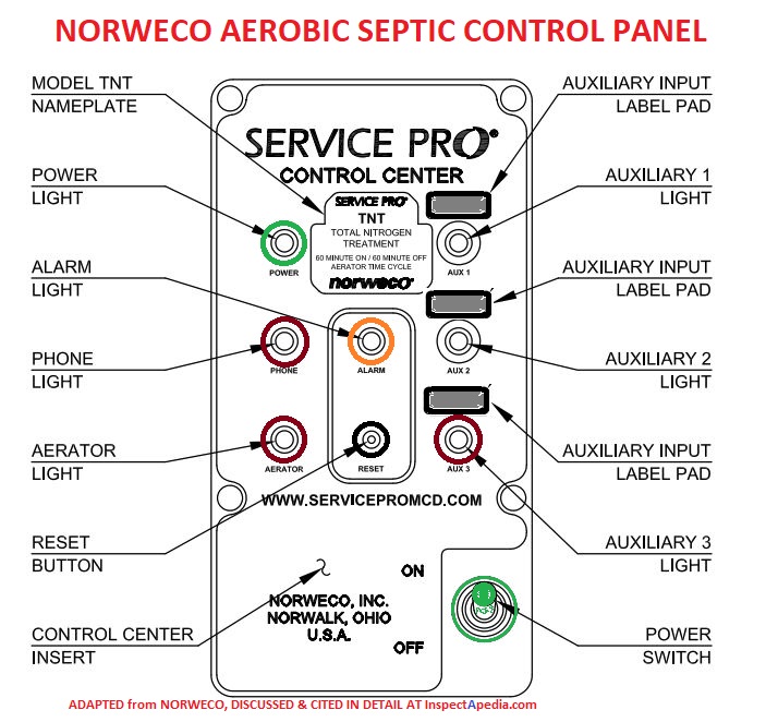
The pump can be controlled either by the use of control floats or by timer controls. series: Electrical wiring, control systems and fluid engineering software. ... WIRING DIAGRAM Included along with the schematic diagram is a wiring diagram and panel internal layout. ... Sump Pumps and Septic Sewage Systems - Jet Aerator Control Panel - Hi. ...
Aug 11, 2010 · 3 posts · 1 authorI made a rough wiring schematic of the way I would like to wire up my aerators and attached it. My boat has 2 fresh water aerators and 2 ...

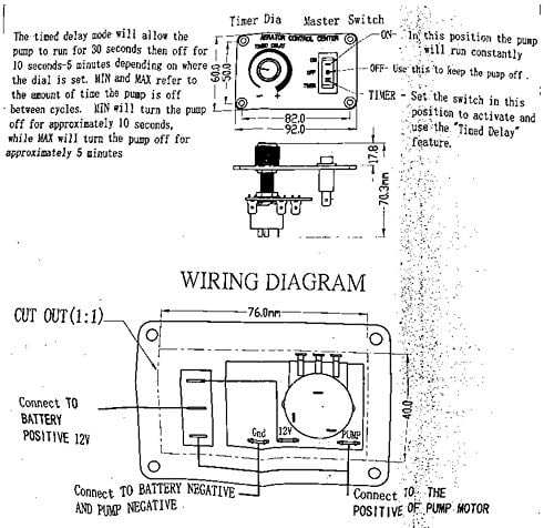
Livewell timer Installation Diagram, Installation Diagram, how to install livewell timer, how to wire a livewell timer, livewell timer wiring diagram.
Congratulations on your purchase of the Flow-Rite ProTimer™. The ProTimer is designed to ... Attach wires as shown in the wiring diagram on the next page.2 pages

This Automatic Aerator Control Pro Timer Plus Adjustable Livewell Timer with Push ON/OFF Switch provides a source of oxygen-rich water to your tank through pump. This unit features soild-state timer ad can be turned on automatically or manually. This product is made of Black Aluminum Plate and is rated at 5 Amps and 12V DC. The timer will run for 30 seconds then can be turned off from 10 ...
.gif)
Hoot Wiring Diagram from imgv2-2-f.scribdassets.com Please select the type of controller you have from hoot for instructions and troubleshooting information: An aerobic treatment system (ats), often called an aerobic septic system, is a small scale sewage treatment system similar to a septic tank system, but which uses an aerobic process for ...
3. They are in a primary wire which carries direct voltage to a primary function component. 4. The wire may appear to be slightly smaller in size than the rest of the wire, which is often where the fusible link exists. Note, the smaller diameter is often less than 1/2" in length so its not real obvious. 5.

Joined Dec 10, 2017. ·. 2,039 Posts. #10 · 9 mo ago. Only show this user. I did an online search for "JD2305 wiring schematic" and found this: As I don't see any reference to 2305 on the pic, I can't verify 100% this IS your actual schematic, BUT! This clearly shows what JimR stated: "X" is a wire connector or detachable plug.

Aug 11, 2010 · 3 posts · 1 authorI made a rough wiring schematic of the way I would like to wire up my aerators and attached it. My boat has 2 fresh water aerators and 2 ...
4 way switch diagram. One ground and 4 circuit terminals divided into two matching pairs called travelers. In this circuit the power comes in through the first switch. Two switches will be 3-way and one will be a 4-way. In the diagrams below the first switch 3-way common terminal connects to line voltage.

01.05.2017 · If your riding mower keeps blowing fuses, learn how to troubleshoot the possible causes. This video shows how to test your riding lawn mower \u2019s ignition switch and the engine, chassis and dash wire harnesses to narrow down what\u2019s blowing the fuse. Craftsman Lt Riding Lawn Mower Manual Find part in diagram CRAFTSMAN Lawn, Tractor Model # This model has a separate ...


0 Response to "36 aerator timer wiring diagram"
Post a Comment