36 auto meter wiring diagram
Power, Precision, Passion – Auto Meter, the most respected manufacturer of high quality, performance aftermarket instrumentation, tachometers, gauges, ...
INSTALLATION INSTRUCTIONS. GPS SPEEDOMETER INTERFACE. Installation . Calibration. 1. The interface module should be mounted away from high heat. For Installing Auto Meter Electric Speedometer, Tachometer, And Short This will require some basic knowledge of automotive electrical, and in some cases a vehicle specific wiring diagram, You may also use this to power a GPS interface.
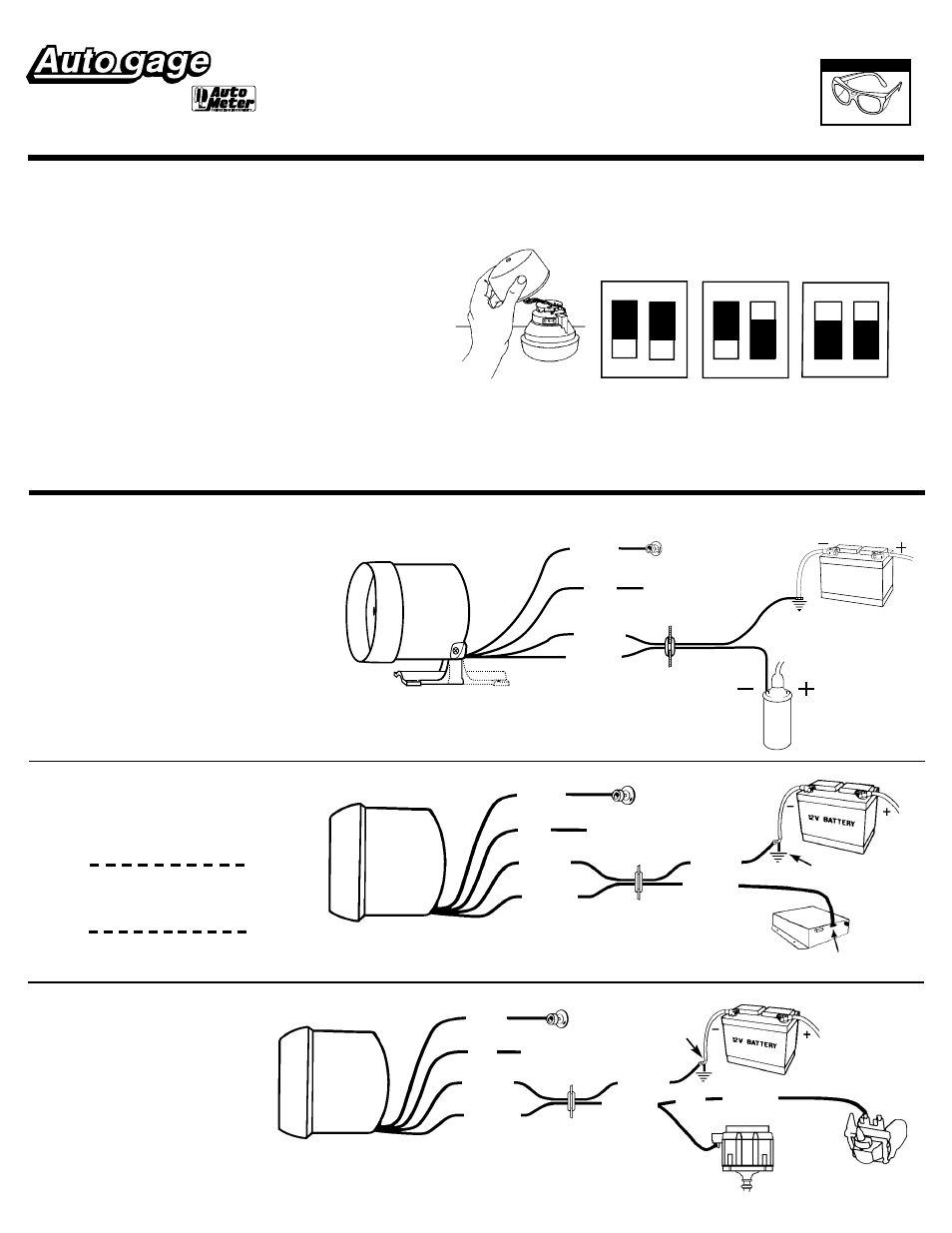
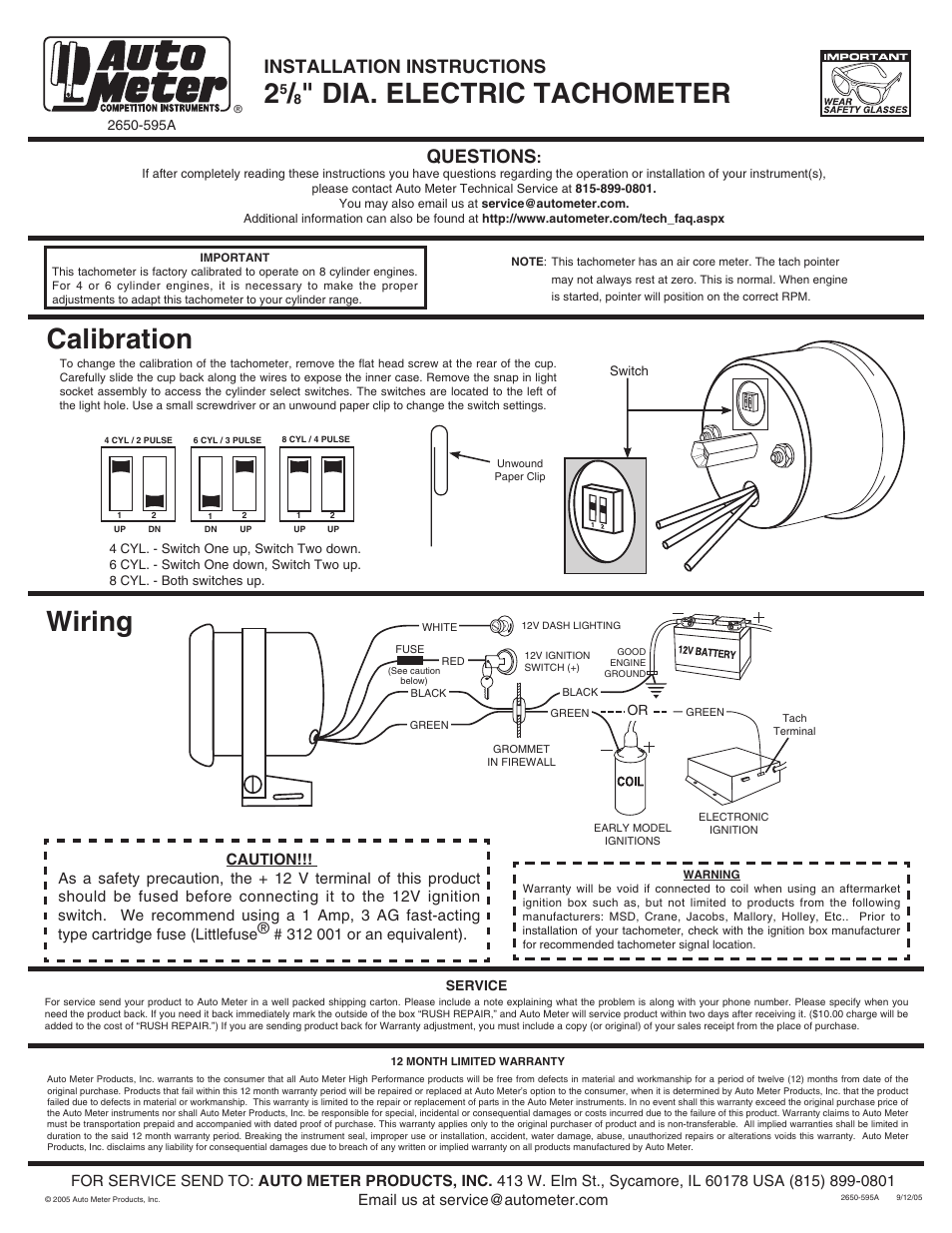
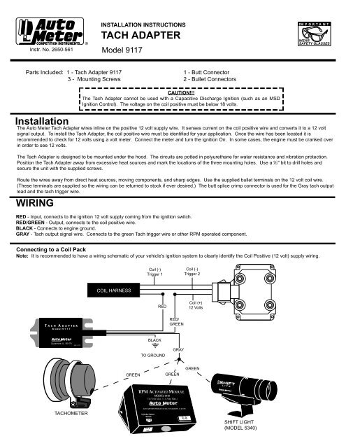
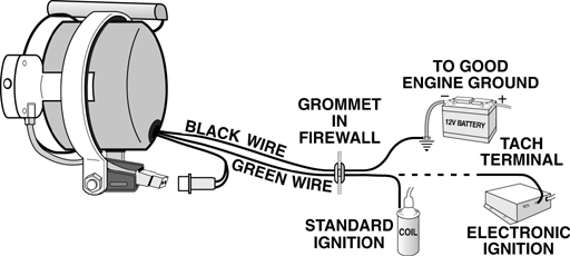
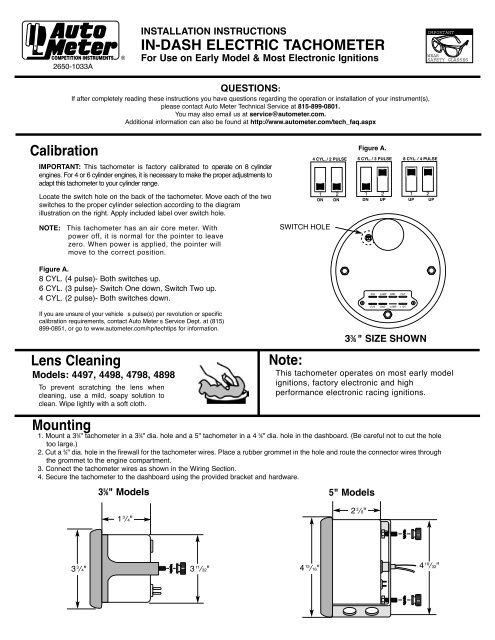
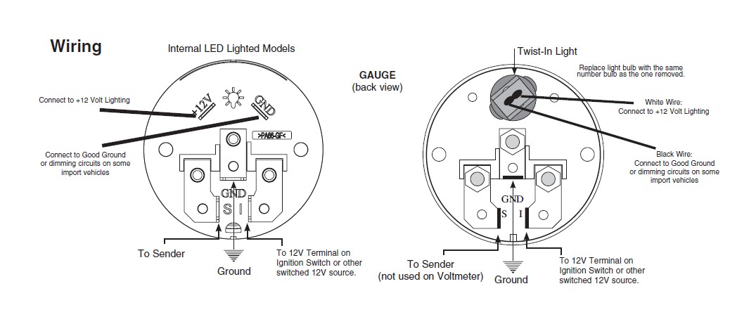
Wiring. The special design of the tachometer base allows for a variety of ... For service send your product to Auto Meter in a well packed shipping carton.

Auto meter wiring diagram
Isspro pyrometer gauge wiring the hull truth boating and fishing forum auto meter 6345 user manual 2 pages also for 6545 6945 weird electrical issues turbo sel register caution 4x4earth autometer c2 pyro place tech egt exhaust gas temperature westach westberg diagram stealth 316 3373 channel intake air temp 5297 wire harness digi stepper incandescent probe 5251 4wheelparts… Read More »
Autometer Gauge Wiring Diagram. Awesome- Encouraged in order to my blog site, within this time I'll demonstrate regarding autometer gauge wiring diagram. . And now, this is the first image: Equus Fuel Gauge Wiring Diagram How To Install An Auto Meter Pro from autometer gauge wiring diagram , source:jennylares.com.
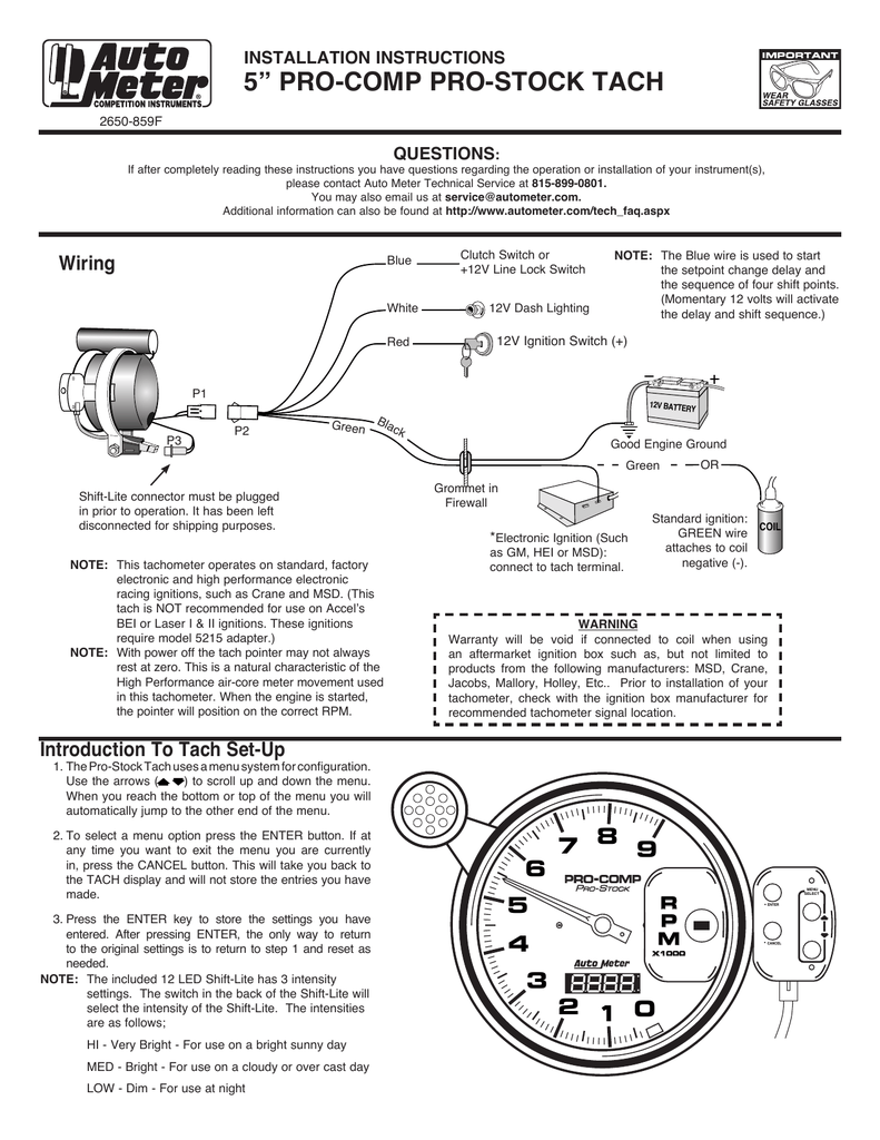
5" tachometer, Introduction, Wiring • Read online or download PDF • Auto Meter 6856 User Manual.
Auto meter wiring diagram.
Aug 15, · Autometer Pyrometer Wiring Diagram auto meter ficial site trade in any aftermarket gauges for credit on new autometer gauges 15 trade in trade up read more auto Autometer Pyrometer Wiring Diagram Isspro Electric Water Temp img source: diagramweb.net Autometer Pyrometer Wiring Diagram As Well As Temperature Gauge img source.
The wiring diagram shown is a typical installation. Figure A ... the light should ever fail, the tach must be returned to AutoMeter for a light replacement.2 pages
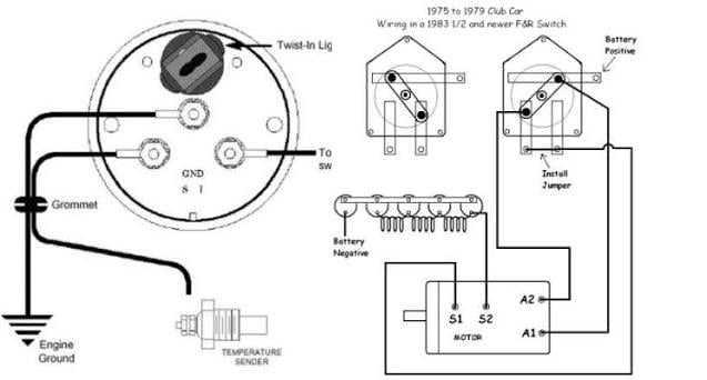
wire to the left connection post as shown in Diagram 2. Do not over tighten. 7. Connect one end of another length of 18-gauge insulated copper wire to the center connection post, as shown in Diagram 2 and the other end of the wire to a good ground source. 8. Connect a third length of 18-gauge insulated copper wire to the right connection post as
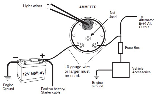
wiring diagram). 4. Connect ammeter lamp (60-0-60-I only) to existing instrument panel lighting circuit. 5. Reconnect the battery ground cable. 6. If ammeter shows a positive charge when starter is engaged, reverse connections on back of ammeter. 5311 S. 122: nd:
The wiring diagram shows installation on vehicles with original equipment ignitions. If your car is equipped with a specialty aftermarket ignition, ...2 pages
auto meter wiring diagram - Exactly What's Wiring Diagram? A wiring diagram is a sort of schematic which utilizes abstract pictorial signs to reveal all the interconnections of parts in a system.
Pictured below is a copy of the wiring diagram for the Autometer Oil Pressure Gauge. To install an oil pressure gauge you will first need to purchase one. Pictured below is a copy of the wiring diagram for the Autometer Oil Pressure Gauge. left is labeled 'S', signal wire from oil pressure or water temp sensor? .
Autometer Tach Wiring Diagram Auto Meter Sport P Electrical Drawing Rh G News Co on random diagrams, auto meter monster tach wiring diagram diagrams.A tachometer is a good addition to any vehicle equipped with a manual transmission. In my Jeep CJ-7, I didn't have one of those rare factory tachs so I chose the Autogage Tachometer /4 inch with an ...
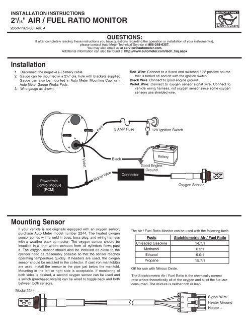
please contact Auto Meter Technical Service at 866-248-6357. You may also email us at service@autometer.com. ... heavier wire for hook-up Note: See Diagram 1 if your terminal arrangement differs from one shown. Note: See Diagram 1 if your terminal arrangement
Autometer Voltmeter Wiring Diagram - wiring diagram is a simplified usual pictorial representation of an electrical circuit. It shows the components of the circuit as simplified shapes, and the capacity and signal associates together with the devices. A wiring diagram usually gives assistance nearly the relative point of view and arrangement ...
Variety of autometer gauge wiring diagram. A wiring diagram is a simplified conventional pictorial representation of an electric circuit. It shows the elements of the circuit as simplified forms, and the power and signal connections in between the devices.
Autometer Volt Gauge Wiring Diagram from www.bangshift.com Print the cabling diagram off and use highlighters in order to trace the routine. When you employ your finger or perhaps stick to the circuit along with your eyes, it is easy to mistrace the circuit. A single trick that I actually 2 to print a similar wiring diagram off twice.
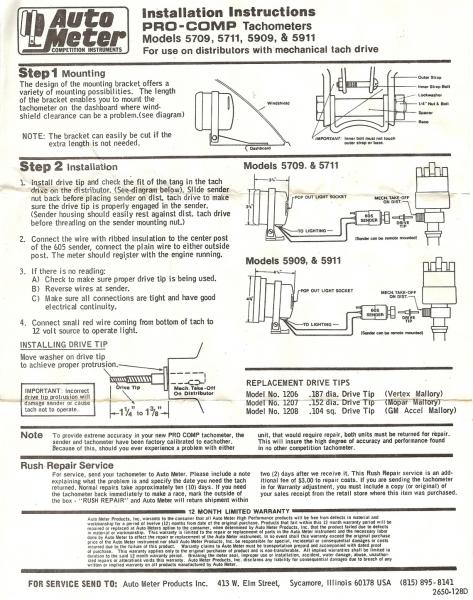
Autometer Sport Comp Tach Wiring Diagram. Wiring. The special design of the tachometer base allows for a variety of mounting For service send your product to Auto Meter in a well packed shipping carton. To operate the Sport-Comp Shift-Lite tachometer, first determine your desired. Sport-Comp Playback Tachometer · DPSS Shift-Light - Level 2 or ...
auto meter fuel gauge wiring diagram wiring diagram perfomance. Architectural wiring diagrams deed the approximate locations and interconnections of receptacles, lighting, and long-lasting electrical services in a building. Interconnecting wire routes may be shown approximately, where particular receptacles or fixtures must be on a common circuit.
Auto gauge tach wiring wiring diagram data autometer gauge wiring diagram. It reveals the components of the circuit as simplified shapes and also the power and also signal connections in between the devices. It contains directions and diagrams for various varieties of wiring strategies along with other things like lights windows etc.
A wiring diagram is a simplified conventional photographic representation of an electrical circuit. 8mount speedometer in a 33 dia. The electronic speedometer in this instrument is designed to operate with an electrical speed sender. W auto meter gps interface. Place a rubber grommet in the hole and route.
Autometer Basic Tach Installation Wiring Instructions Tutorial How-To http://www.jegs.com/webapp/wcs/stores/servlet/KeywordSearchCmd?manufacturer=Auto%20Mete...
SPARk PLUg WiRES. *See autometer.com/tech_installation.aspx for specific vehicle information. *. CAUTION!!! As a safety precaution the RED wire of this ...
Autometer Pro Comp Ultra Lite Wiring Diagram Fresh Auto Meter Wiring - Autometer Gauge Wiring Diagram Wiring Diagram arrives with several easy to follow Wiring Diagram Guidelines. It's intended to aid all the average person in developing a suitable method. These guidelines will be easy to understand and apply.
Autometer Tachometer Wiring Diagram - wiring diagram is a simplified gratifying pictorial representation of an electrical circuit. It shows the components of the circuit as simplified shapes, and the aptitude and signal connections between the devices.
Auto Meter Products. 413 W Elm St. Sycamore, IL 60178. Toll Free Tech Support: 866.248.6357. Toll Free Customer Service: 866.248.6356. International: 815.895.8141
Recommended - Auto Meter Hall effect sender, 3-wire 16 pulses/revolution. 5291 Standard 7/8 - 18 thread 5292 Ford, plug in Mounting 1. 8Mount speedometer in a 33/ " dia. hole. Be careful not to cut the hole too large. 2. 8Cut a 3/ " dia. hole in the firewall for the speedometer wires. Place a rubber grommet in the hole and route
White Wire: Connect to +12 Volt Lighting. INSTALLATION INSTRUCTIONS. SHORT SWEEP ELECTRIC GAUGES. 2650-1079-00 Rev. C. Mounting. Replace light bulb with the same . number bulb as the one removed. These gauges can be mounted in-dash or in Auto Meter mounting solutions (panels, cups, pods, etc.). 2. 1 ⁄ 16" diameter gauges mount in 2. 1 ⁄ 16 ...
Gauge Voltmeter Wiring Diagram Png 1200x1200px Ammeter Ampere Direct Cur Free. Electric Gauges. Catalog. How To Install Auto Meter Voltmeter Gauge Electrical Jeep Logo On Your 87 18 Wrangler Yj Tj Jk Jl Extremeterrain. Classic Style 60 160 Vdc Voltmeter Electric Car Parts Co. 2 5 8 Voltmeter 10 16v Air Core Short Sweep Auto E.
Auto Meter Voltmeter Wiring Diagram Pdf Files Ebooks Epubs. Car Voltmeter Wiring Diagram Wiring Diagram. Led Voltage Meter Wiring Diagram On Car Amp Meter Wiring Diagram. Mercruiser Tachometer Wiring Travelersunlimited Club. Autometer Gauge Wiring How To Install An Auto Meter Pro P Ultra Lite.
Diagram autometer volt gauge wiring full version hd quality bjjdiagram mbreporter it how to install auto meter voltmeter electrical jeep logo on your 87 18 wrangler yj tj jk jl extremeterrain troubleshooting boat gauges instrumenteters boatus 3 ways a car amp wikihow installation instructions for cobalt air fuel ratio digital 79 17 all americanmuscle mad with already installed… Read More »
Wiring your new Autometer tachometer into your car will complete the installation. Once you have selected a mounting location, you can run the four wires that operate the tachometer. The tachometer is designed to show the engine RPMs or rotations per minute. Autometer has designed their tach to be used with four, six ...
Existing wires may be used, or route proper length of 18 gauge, 2 conductor wire from fuel tank to gauge. Connect one end to terminal post on fuel level.2 pages
The wiring diagram shown is a typical installation. For Chrysler Blue, Gold and Silver Boxes, Ford Standard Electronic ... Auto Meter Products, Inc. warrants to the consumer that all Auto Meter High Performance products will be free from defects in material and workmanship for a period of twelve (12) months from date of the ...
Autogage by Autometer Wiring Diagram - wiring diagram is a simplified normal pictorial representation of an electrical circuit. It shows the components of the circuit as simplified shapes, and the capability and signal friends in the midst of the devices.










0 Response to "36 auto meter wiring diagram"
Post a Comment