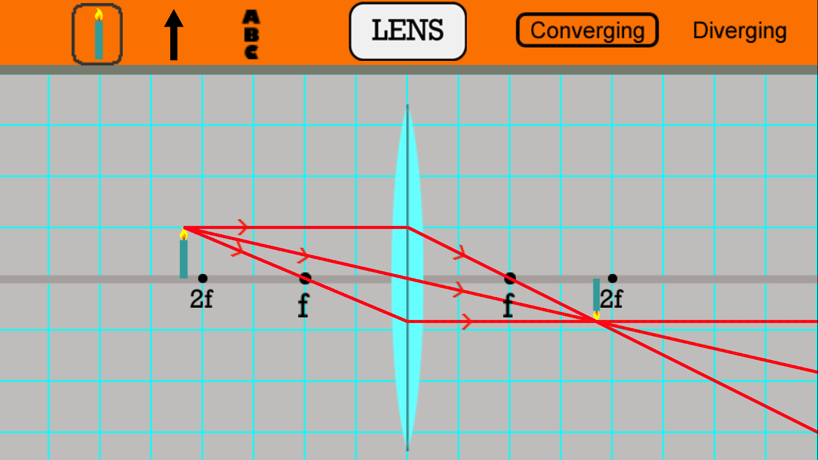
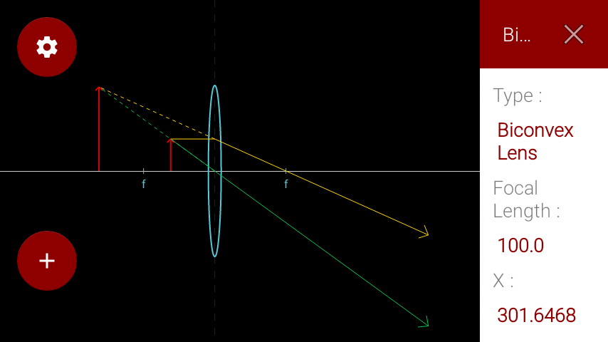
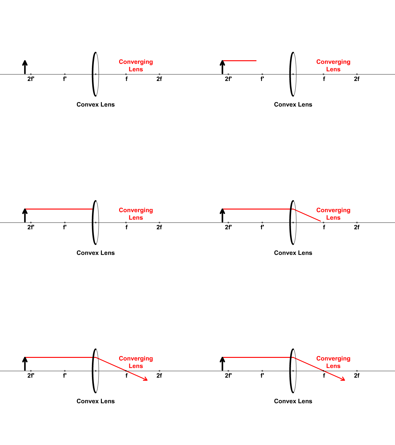
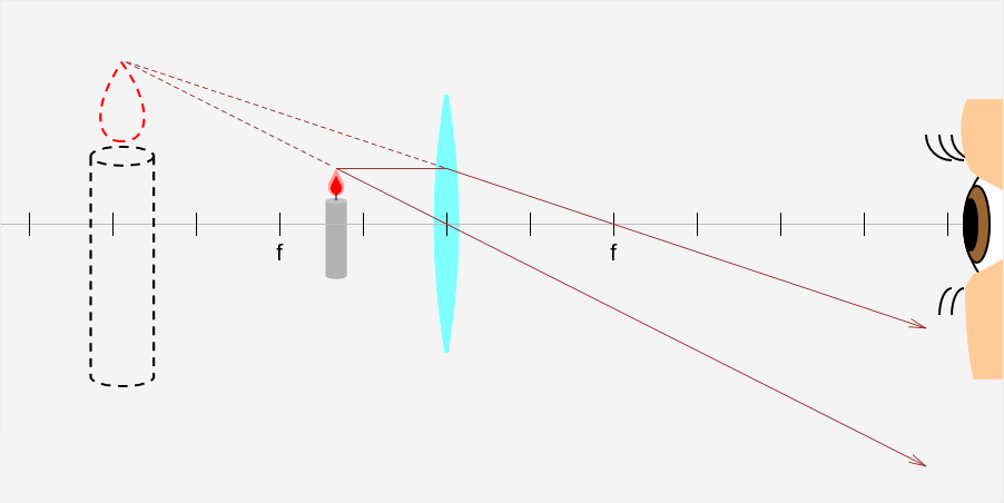
36 converging lens ray diagram simulation
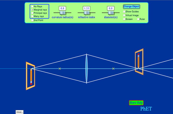
PhET Simulation: Geometric Optics. PhET Simulation: Geometric Optics. published by the PhET. This interactive Flash application allows users to investigate the properties of converging lenses. The index of refraction and the radius of curvature of the lens can be changed and thelens and object can be moved in two dimensions.
oPhysics: Interactive Physics Simulations. Concave and Convex Mirrors. Concave and Convex Mirrors - GeoGebra Materials. Description. Simulation of image formation in concave and convex mirrors. Move the tip of the Object arrow or the point labeled focus. Move the arrow to the right side of the mirror to get a convex mirror.
second lens. A ray diagram using this virtual object shows the location of the final image (bottom part of Figure O4.3). Numerically, we can verify the accuracy of the ray diagram with: An arrow is placed 50 cm away from a converging lens (f= 25cm). On the other side of this first lens is a second converging lens (f=

Converging lens ray diagram simulation
• Any ray can be traced through the lens system using the oblique-ray method • For example, trace the axial ray - point of intersection with axis in image space gives image location L1 L2 F1 F1' F2 F2' Object parallel a x i a l r a y Image parallel second focal plane of lens1 second
A converging lens is an optical lens that converges all rays of light passing through it. The primary purpose of a converging lens is to focus the incoming rays from an object and converge them to form an image. The image can be magnified, diminished, or remain the same depending on the distance of the object from the lens.
Lenses are traditionally shaped as sections of spheres, such that the radius of curvature of the sphere of which they are comprised can describe the lens' curvature. The diagram of an eye and lens to the right demonstrates this concept. Lenses show up in nature in the eyes of animals.
Converging lens ray diagram simulation.
• Light rays bent towards each other… CONVERGING LENS. • The less parallel the two sides, the more the light ray changes direction. • Rays from a single point, converge to a single point on the other side of the lens (and then start diverging again). We build lenses out of glass with non-parallel sides Put film, Retina here!
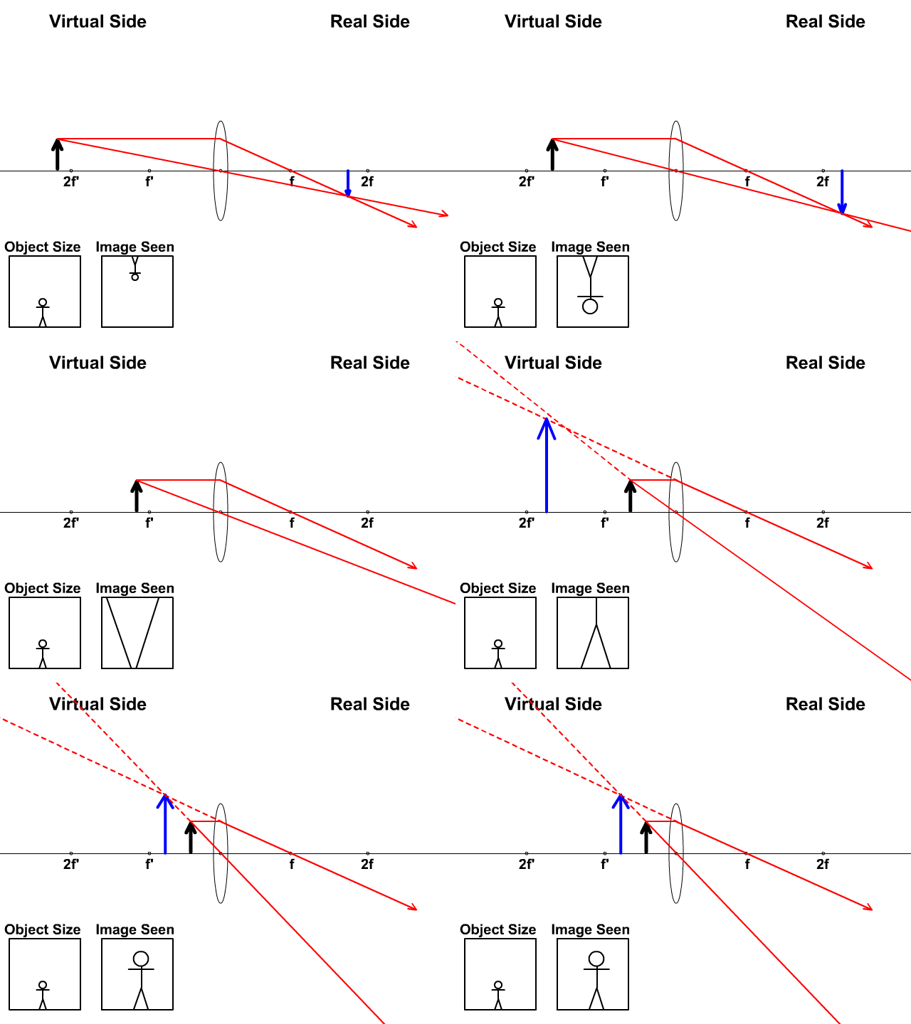
Ray diagrams for converging lens cases. Here is a video from Khan Academy that shows the ray geometry that explains the image formation for four different object distances relative to the lens and its focal points. A few key concepts are: YouTube. Light is reflecting from the o bject in all directions, but the only rays shown are the ones that ...
Converging lens: A converging lens focuses diverging or blurry light rays from a distant object by refracting (bending) the rays twice. Its curvature converts rays to a focal point behind the lens so that a sharper image can be seen or captured on a screen or camera sensor.
Get Physics Help Online from our Expert Physics Tutors. Avail a Free Physics Tutoring Session and get Help with Physics Concepts from the Physics Problem Solver.
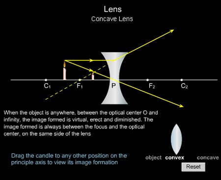
A concave lens is a piece of round glass that is thinner at the centre than at the edges. It bends the rays of light passing through it away from each other i.e. diverges them. Opticians use concave lenses to correct nearsightedness.
April 11, 2020 - Convex lens forms real image because of positive focal length and concave lens forms virtual image because of negative focal length.
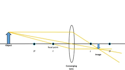
When the object is outside the converging lens' focal point, F, the resulting image is real, inverted and on the side of the lens opposite the object. This is shown with the geometrical ray diagram of Figure 4. Figure 4. An object outside the lens' focal point forms a real and inverted image on the side of the lens opposite the object.
The image formed by a single lens can be located and sized with three principal rays. Examples are given for converging and diverging lenses and for the cases where the object is inside and outside the principal focal length · The "three principal rays" which are used for visualizing the image ...
Converging Lenses A convex lens is a converging lens which bends light rays into focus. The focal length, f, is the distance to the focal point where parallel rays converge as shown. A Ray Diagram is a simple picture using only 2 or 3 light rays reflected off an object to visualize how images are formed.
December 25, 2015 - Trick to drawing ray diagrams for converging lens: There is one ray of light passing through the center of the lens. Always. 2 rays are enough to determine the position of image/object. The other r…
Converging Lens. Diverging Lens. F. Ray 1. F Ray 1. Ray 2. Ray 2. Ray 3 Ray 3. Images' ' Tracing Points Draw an arrow to represent the location of an object, then draw any two of the rays from the tip of the arrow. The image is where lines cross. Draw an arrow to represent the location of an
• Construct ray diagrams to accurately show how an image is formed ... A converging lens could be used to create an image with .=−2. B. A diverging lens could be used to create an image ... Run two scenarios using the hidden lens simulation. If the frame does not open properly in your Pivot window, in a new window.
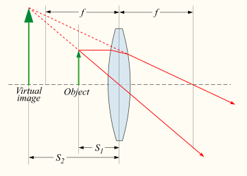
Real images occur when objects are placed outside the focal length of a converging lens (s>f). If the lens is converging but the distance from the object to the lens is smaller than the focal length, the image will be virtual. Diverging lenses always produce virtual images. This calculator shows a ray diagram when the image is real. Magnification
Here you have the ray diagrams used to find the image position for a diverging lens. A diverging lens always form an upright virtual image. Ray diagrams are constructed by taking the path of two distinct rays from a single point on the object: A ray passing through the center of the lens will be undeflected. A ray proceeding parallel to the principal axis will diverge as if he came from the ...
122 - Ray Diagrams - LensesIn this video Paul Andersen explains how ray diagrams for lenses can be used to determine the size and location of a refracted ima...
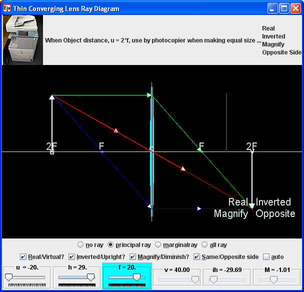
What does the term linear magnification mean in this simulation. Discuss how it is calculated from? How many ways are there to determine the magnification of the think converging lens. Check the no ray radio button. move the sliders a suitable position of your choice. Now, sketch as accurately as possible on a piece of paper, the principal ray diagram ...
August 9, 2020 - Explain how an image is formed by a converging lens using ray diagrams.
Dragging the focal points to the other side of the lens will change the lens from converging to diverging and vice versa. Click on "Switch Rays" to show one principle ray at a time. This simulation focuses on showing the rules regarding the principle rays so the image is purposely omitted. See the next simulation to learn how to find the image.
September 5, 2021 - Real image and virtual image Looking at an object, we feel there is an object in it. By the way, if you feel that there is something, we say there is an… Read more
Diverging lens. Author: Ray Tuck. This simulation shows a ray diagram for a diverging lens. Use the slider to set the position of the object. The object is shown by a black arrow. Use the check boxes to choose which rays to show. You need any two to fix the position of the image. The image is shown by the red arrow.
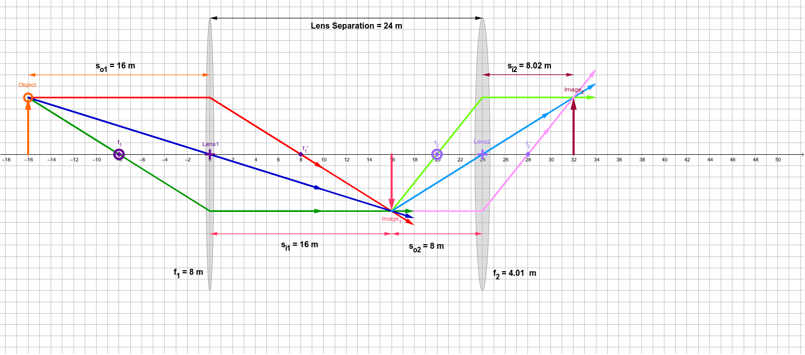
Barb Newitt. This simulation shows a lens combination of 2 converging lenses. Adjust the position of the orange circle to adjust the object position. Adjust the position of the purple focal point circles to adjust the focal lengths of the two lenses. Adjust the position of the purple Lens2 + to adjust the position of Lens 2.
This work by Andrew Duffy is licensed under a Creative Commons Attribution-NonCommercial-ShareAlike 4.0 International License. This simulation can be found in the collection at http://physics.bu.edu/~duffy/classroom.html · The counter has been running on this page since 8-14-2018.
Ray Optics Simulation. An open-source web application to simulate reflection and refraction of light. ... , including prisms and "spherical" lenses. Glass (Ideal lens) An ideal lens which obeys exactly the thin lens equation (1/p + 1/q = 1/f). The focal length (in pixels) can be set directly. ...
Ray diagram for a converging or diverging lens; Nice variation of the previous simulation by John Welch, showing the lens changing shape; Test yourself - what's behind the curtain? (Lenses) Puzzle - find the focal length of the lens (I) Puzzle - find the focal length of the lens (II) Puzzle - find the focal length of the lens (III)
Lens and Mirror Lab. Category. Optics, Physics. Change the location of the object and use the ray diagrams to determine the location of the image. The following lab was created by Nick Donovan. Thanks Nick! Recommended Lab:
physics-simulation. A collection of interactive physics simulations. Fork on GitHub. Elastic Collision. Simulates an elastic collision between two particles. Thin Lens. Draws the ray diagram for a thin converging or diverging lens.
This interactive tutorial utilizes ray traces to explore how images are formed by the three primary types of converging lenses, and the relationship between the object and the image formed by the lens as a function of distance between the object and the focal points.
What does the term linear magnification mean in this simulation. Discuss how it is calculated from? How many ways are there to determine the magnification of the think converging lens. Check the no ray radio button. move the sliders a suitable position of your choice. Now, sketch as accurately as possible on a piece of paper, the principal ray diagram ...
22 Oct 2016 — HTML5 app: Image formation by converging lenses. ... Principal light rays. Bundle of light rays. Emphasize:.
to save your graphs! New Blank Graph.
Converging Lens Image Formation. The Converging Lens Image Formation Interactive provides learners with a virtual light box for exploring the refraction of light through converging lenses and the manner in which such refraction leads to the formation of an image of a complex object. Learners tap on various points upon an object.
The Physics Classroom serves students, teachers and classrooms by providing classroom-ready resources that utilize an easy-to-understand language that makes learning interactive and multi-dimensional. Written by teachers for teachers and students, The Physics Classroom provides a wealth of ...
Author: Barb Newitt. This simulation shows a diverging lens in combination with a converging lens. Adjust the position of the orange circle to adjust the object position. Adjust the position of the purple focal point circles to adjust the focal lengths of the two lenses. Adjust the position of the purple Lens2 + to adjust the position of Lens 2.
Ray Diagram for Object Located in Front of the Focal Point. In the three cases described above - the case of the object being located beyond 2F, the case of the object being located at 2F, and the case of the object being located between 2F and F - light rays are converging to a point after refracting through the lens. In such cases, a real image is formed.
This collection of interactive simulations allow learners of Physics to explore core physics concepts by altering variables and observing the results. This section contains more than 70 simulations and the numbers continue to grow.
This Demonstration lets you visualize the ray diagrams for converging and diverging lenses. By manipulating the object and lens locations, you can create real or virtual images. The rays parallel to the principal axis and the ray through the center of the lens are drawn.Locators allow you to drag both the object and the lens. You can change the focal length using a slider.
Description. Simulation of image formation in concave and convex lenses. Move the tip of the "Object" arrow to move the object. Move the point named " Focus' " to change the focal length. Move the point named " Focus' " to the right side of the lens to change to a concave lens.
Here you have the ray diagrams used to find the image position for a converging lens. You can also illustrate the magnification of a lens and the difference between real and virtual images. Ray diagrams are constructed by taking the path of two distinct rays from a single point on the object. A light ray that enters the lens is an incident ray.











0 Response to "36 converging lens ray diagram simulation"
Post a Comment