36 delay on break timer wiring diagram
Delay On Break Timer Wiring Diagram . Best Of Delay On Break Timer Wiring Diagram . Wiring Diagram for Extractor Fan with Timer Fresh Manrose Extractor. Omron H3ca A Wiring Diagram Beautiful Help Me Wire Up An Omron H3y 2. 555 Delay Timer Circuit Diagram Luxury Opamp Komparator Od 555 Cmos The MC-25 (PN: 10MC25) is a delay on make, delay on break time delay. It is perfect to use when either a magnetic lock or electric strike is installed on an automatic door. The delay on break timer will release the lock and then the delay on make timer will enable the door to open and be held open for a set period of time.
How to Wire A Time Delay Relay Diagrams – wiring diagram is a simplified enjoyable pictorial representation of an electrical circuit. It shows the components of the circuit as simplified shapes, and the gift and signal contacts along with the devices. A wiring diagram usually gives guidance roughly the relative slant and bargain of devices ...

Delay on break timer wiring diagram
DOWNLOAD. Wiring Diagram Pictures Detail: Name: delay on break timer wiring diagram – off delay timer wiring diagram Beautiful Awesome Eagle Signal Timers Wiring Diagram Inspiration. File Type: JPG. Source: kmestc.com. Size: 211.68 KB. Dimension: 1858 x 1046. DOWNLOAD. Wiring Diagram Pics Detail: Works with 24, 120 or 240 VAC control circuits. Supports up to 1.5 Amps. Two wire hookup for easy installation. Solid state with quick disconnect terminals. Operation (Delay-on-Break) Input voltage must be applied before and during timing. Upon closure of the initiate switch, the output relay energizes. The time delay begins when the initiate switch is opened. The output remains energized during timing. At the end of the time delay, the output de-energizes.
Delay on break timer wiring diagram. Before going into detail of Time Delay Circuit, first we need to learn about 555 Timer IC first.Below you can find the pin diagram of 555 timer IC along with the details of each pin. Pin 1. Ground: This pin should be connected to ground. Pin 2. TRIGGER: Trigger pin is dragged from the negative input of comparator two.The comparator two output is connected to SET pin of flip-flop. Delay On Break Timer Wiring Diagram. Assortment of delay on break timer wiring diagram. A wiring diagram is a streamlined traditional photographic representation of an electrical circuit. It shows the elements of the circuit as streamlined shapes, as well as the power and signal connections between the gadgets. A wiring diagram usually offers info concerning the… 6 Mar 2018 — What's the difference between DOM and DOB? Let's try to answer that and give some real-world examples of applications where each could be ... the external initiate switch opens, the time delay is started. At the end of the time delay, the load is de-energized, and the timer is ready for another cycle. CUBE RELAY, 10-30 AMPS Timing Mode: DELAY ON BREAK Category: TIMER WITH RELAY Series: TGM 072816 PELCO COMPONENT TECHNOLOGIES • 855 227 3526 SPECIFICATIONSFEATURES
Delay On Break Timer Wiring Diagram. Print the cabling diagram off and use highlighters to trace the routine. When you make use of your finger or perhaps follow the circuit along with your eyes, it’s easy to mistrace the circuit. A single trick that I actually 2 to printing a similar wiring picture off twice. sounds like it is working properly,a delay on break initializes the time circuit when the unit shuts off from the last cycle,you may be thinking of a delay on make timer which wouldnt bring the compressor on until after the stat has called and then it goes through the timer..if it has been 5 minutes,or less whatever the timer is set for,and the stat calls,it WILL and should all come on at once.. TIME DIAGRAM Example: Delay-on-Break (Release) Input Applied Off Output Energized (Normally De-energized Open) Initiate Closed Switch Open R = Reset TD = Time Delay S1 = Initiate Switch Undefined time t = Incomplete Time Delay Appendix A - Timer Functions. www.ssac.com ... Stop Timer Before Time Off Electrician Talk. Dayton Multi Function Timing Relay 120v Ac 10a 240v 11 Pins Dpdt 6a855 Grainger. Diagram Wiring For Timer Off Delay On Lights Biedisp Mevalarte It. Diagram A Relay Wiring Vernetp Trasportopiu It. Need To Wire In A Dayton 11 Pin Time Delay Relay Pull 120v Contactor On Motor Starter For It Run Set.
MARS 32392 - Adjustable Delay on Break Time Delay - MARS Solid State Timers - Delay On Break MARS solid state delay on break timers are designed to prevent short cycling of air conditioning, refrigeration and heat pump compressors. Upon application of power the load is energized. When the thermostat opens, or if there is a momentary loss of power, the load is de-energized and the delay period ... Both devices are fixed 5 minute delay on break timers. Features: • 1 to 3 second random re-start. • Models for two-wire or three- ...5 pages On Delay Timer and off Delay Timer: Generally, timers are used to control the circuit for a certain amount of time. Using timers we can delay the circuit operation. Three types of timers are the most commonly used in the electric circuit. One is On-delay timer, the second one is off relay timer and the third one is star delta timer. The time delay on break, how it works, how to wire into low voltage,and why you should have it on your compressor. Thanks for watching!- DavidDavid@DavidJone...
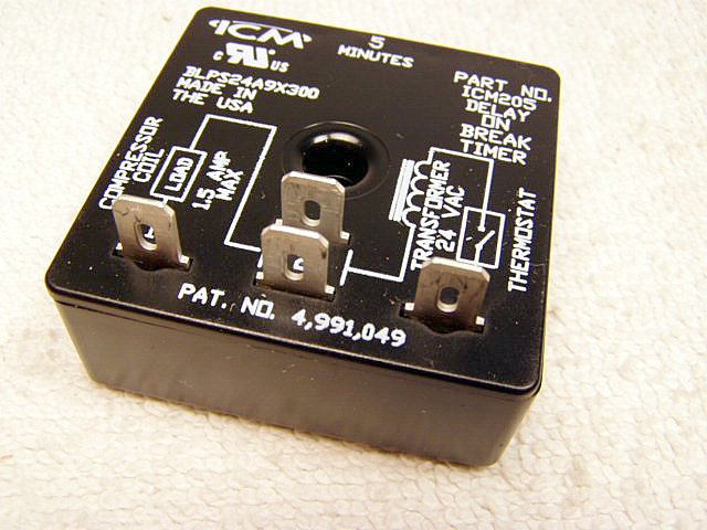
Appliance Parts and Supplies A/C Air Conditioning, Refrigeration and Heat Pump Delay-on-Break Timer ICM203 Delay on Break Timers ("anti-short cycle", "ON delay on break") helps to protect air conditioning, refrigeration and heat pump equipment from damage which may be caused by the rapid short cycling of compressors €¢ 03-10 minute adjustable time delay €¢ 18-240 VAC €¢ 1.5 Amp €¢ ...

Delay On Break Timer Wiring Diagram Gallery. Variety of delay on break timer wiring diagram. A wiring diagram is a simplified traditional pictorial depiction of an electric circuit. It reveals the parts of the circuit as streamlined shapes, and the power as well as signal links between the devices. A wiring diagram generally provides details about the…

Simple Delay Timer Circuits Explained. In this post we discuss the making of simple delay timers using very ordinary components like transistors, capacitors and diodes. All these circuits will produce delay ON or delay OFF time intervals at the output for a predetermined period, from a few seconds to many minutes.
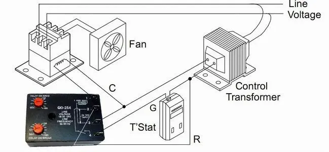
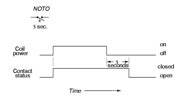
Time delay is factory preset to one specific time 5 seconds for example. Delay on break 6333 daedalus drive cicero ny. Module load at pin 2 is a relay coil. Variety of delay on break timer wiring diagram. The external initiate switch opens the time delay is started. Tgm 072816 pelco component technologies 855 227 3526 specificationsfeatures.
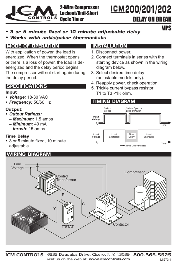
MARS Solid State Timers Delay On Break MARS solid state delay on break timers are designed to prevent short cycling of air conditioning, refrigeration and heat pump compressors. Upon application of power the load is energized. When the thermostat opens, or if there is a momentary loss of power, the load is de-energized and the delay period ...
5 Volt. Omron Timer Relay Wiring Diagram. IC 4060 Timer Circuits. Using 555. Arduino Relay Timer. Off Delay Timer Wiring Diagram. Clock Circuit Diagram. 555 Adjustable Timer Circuit. Peter Lindbergh Photography.
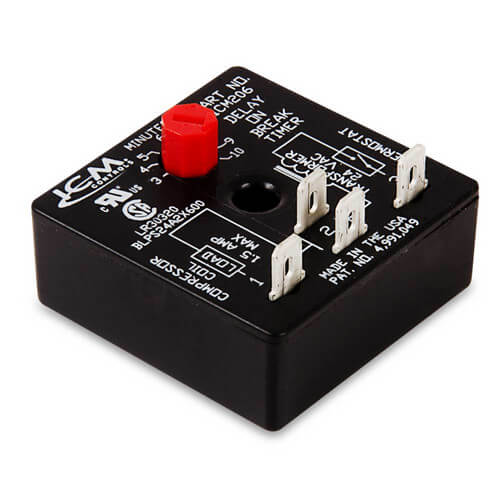
Delay on Break Timer Compressor lockout/Anti-Short cycle timer helps to protect compressors from damage caused by rapid short cycling simple, 2-wire hookup adjustable timing universal voltage. made in United States. Manufactured by ICM Controls. ...

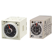
Timing Mode: Delay on Break Type: Digital CMOS Time Range: 0.1 second to 24 hours Time Adjustments: Factory-fixed time period; variable, with adjustments on timer, or terminals for external resistor or potentiometer Repeatability: ±0.5% Setting Accuracy: Fixed time period: ±10% of nominal time. Variable time range: +15% -5% max. time, -10% ...
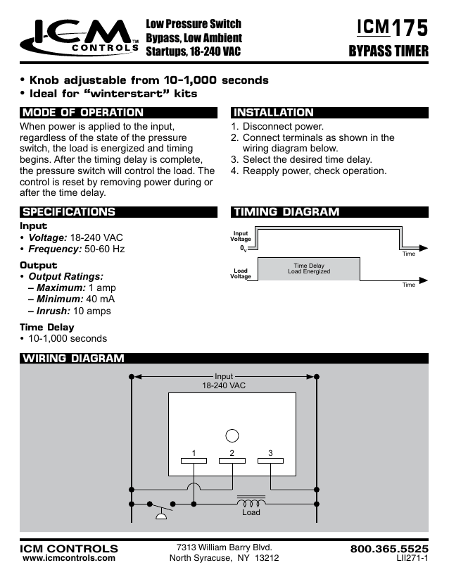
Connect terminals as shown in the wiring diagram below. 3.Select desired time delay (adjustable models only). 4.Reapply power, check operation.

Time Delays (Adjustable Only) • ON delay: 1-180 seconds • OFF delay: 12-390 seconds INSTALLATION 1.Disconnect power. 2. Connect terminals as shown in the wiring diagram below. 3. Select desired delay on make and delay on break periods. 4. Reapply power, check operation. MODE OF OPERATION Power must be applied at all times.

How to wire Dayton Off Delay Timer. ... Why the 3-way switch diagram works... because the switch is ON full time. ... ICM 203 delay on break manual .pdf
Today we will go over what is a HVAC delay on make timer and how it works, how to wire the delay on make timer and when to use a delay on make time delay for...

ICM Controls ICM206B - ICM206 Delay on Break Timer (3-10 Minute Adjustable Delay) - Delay on Break Timers ("anti-short cycle", "ON delay on break") helps to protect air conditioning, refrigeration and heat pump equipment from damage which may be caused by the rapid short cycling of compressors. Features Brownout protection UL 873 recognition as ...

wiring diagram below. 3. Time Delay on break for compressor. Select desired time delay. (adjustable models only). A/C Air Conditioning, Refrigeration and Heat Pump Delay-on-Break Timer - Part# ICM203. 4. Reapply power, check operation. MODE OF OPERATION. With application of. Non-Programmable Thermostats. New Construction.
On Delay Timer Wiring Diagram . On delay timer wiring diagram delay on break timer wiring diagram off delay timer wiring diagram delay on make timer wiring diagram dayton off delay timer wiring diagram 4.11.stiveca.nl
Description. Description. This is a BRAND NEW Universal Anti-Short Cycle Time Delay Relay with Part # ICM212 (also ICM212B & Z1704-4D)- Made in theUSA! It is a Delay on Break relay which means that whenever the power is turned off the relay will time 5 minutes before allowing voltage to pass through it again. This relay accepts 24 input voltage.
ADJ DELAY-ON-BREAK. Timer Type Delay on Break (Anti-Short Cycle) Voltage Range 18-240Vac Amp Rating 1 Time Delay Range 0.1 - 5 Minutes Connection Type Quick Connect Type of Adjustment Knob Hz Rating 50/60. Item #: 32392. Catalog Page (Eng) . .

Delay) - Delay on Break Timers ("anti-short cycle", "ON delay on break") helps to protect ... from damage caused by rapid short cycling Simple 2 wire hookup.

Operation (Delay-on-Break) Input voltage must be applied before and during timing. Upon closure of the initiate switch, the output relay energizes. The time delay begins when the initiate switch is opened. The output remains energized during timing. At the end of the time delay, the output de-energizes.

Works with 24, 120 or 240 VAC control circuits. Supports up to 1.5 Amps. Two wire hookup for easy installation. Solid state with quick disconnect terminals.
DOWNLOAD. Wiring Diagram Pictures Detail: Name: delay on break timer wiring diagram – off delay timer wiring diagram Beautiful Awesome Eagle Signal Timers Wiring Diagram Inspiration. File Type: JPG. Source: kmestc.com. Size: 211.68 KB. Dimension: 1858 x 1046. DOWNLOAD. Wiring Diagram Pics Detail:


0 Response to "36 delay on break timer wiring diagram"
Post a Comment