36 vga to rca converter circuit diagram
3 answersVGA uses a RGBHV signal (5-wire component) while a single RCA cable (usually denoted with a yellow jack) would be a ... Use the following schematics:. The Video Graphics Array (VGA) connector is a standard connector used for computer video output. Originating with the 1987 IBM PS/2 and its VGA graphics system, the 15-pin connector went on to become ubiquitous on PCs, as well as many monitors, projectors and high-definition television sets.. Other connectors have been used to carry VGA-compatible signals, such as …
Vor 2 Tagen · As a simple test to make sure my board was working, I used Cga To Vga Converter Circuit Diagram. c itself)). cga to vga converter gbs-8220 Betson Imperial Parts & Service offers a full line of parts and service to the coin-operated amusement, vending, office coffee service, gaming and billiard industries. Input Horizontal Frequency Rate 12kHz to 40kHz …
Vga to rca converter circuit diagram
This circuit is designed for converting normal VGA signals standard RGB signals and composite sync signal. The circuit is quite simple, because RGB signal ouput ... Rf signal amplifier circuit diagram. 2. 1 circuit diagram of class B push pull amplifier 6 1. 4ghz rf transmitter AN282 MAX2472 HP-E4433B DSSS transmitter complete circuit diagram for a PA amplifier circuit diagram of 2. If I fit a splitter, the picture breaks up!" A. LM386 audio probe amplifier is an essential tool for troubleshooting audio stages in audio related circuits such as … Rs232 to rs485 cable pinout diagram at pinoutsru for rs232 to rs485 wiring diagram image size 836 x 500 px and to view image details please click All the UARTs pins are TTL compatible, including TD, RD, RI, DCD, DSR, CTS, DTR and RTS, so direct usage of pinouts for connecting to serial port is not possible. This is the simplest solution to connecting the two computers. …
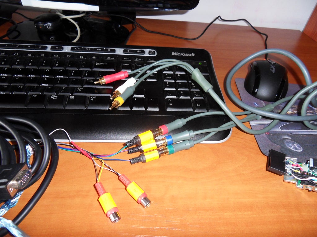
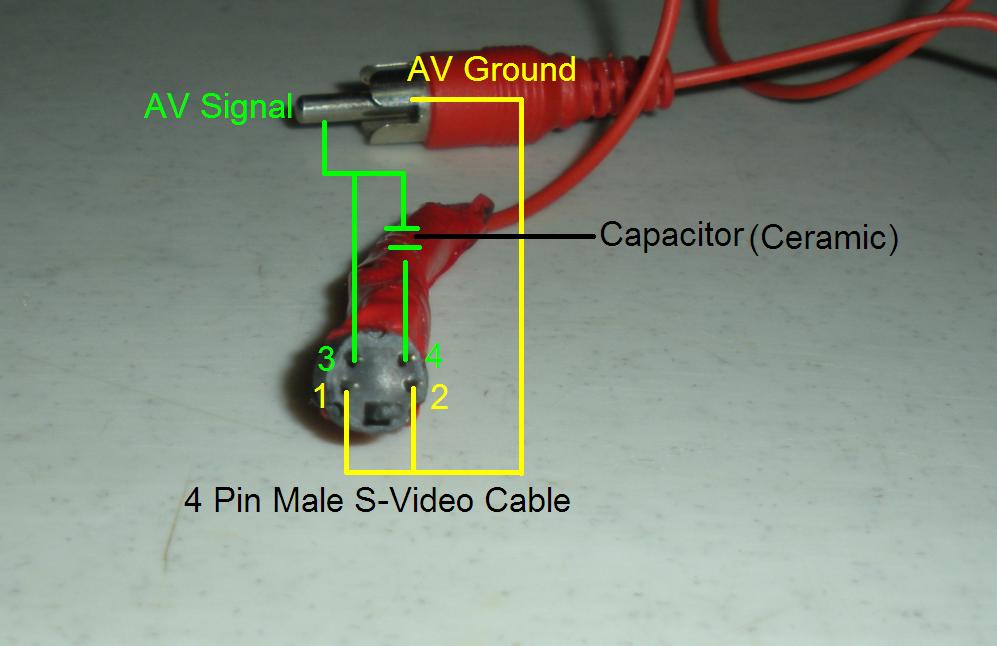
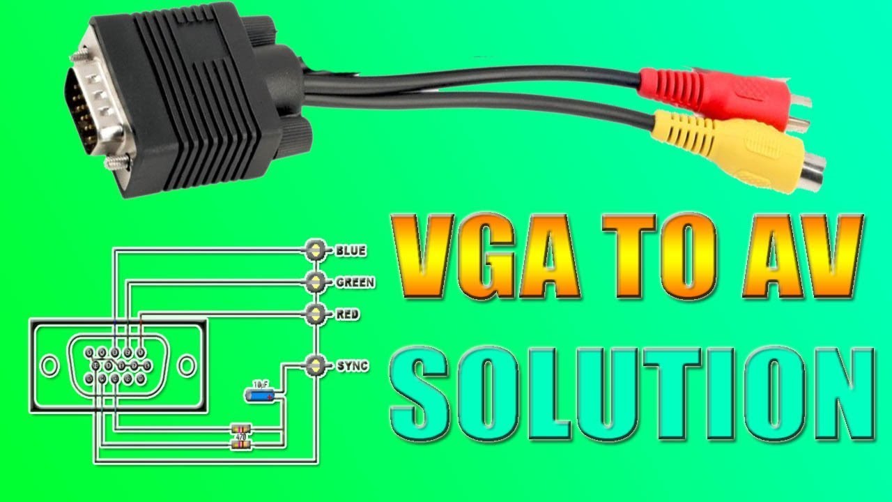
Vga to rca converter circuit diagram. Oct 15, 2017 - Vga To Rca Wiring Diagram Vga To Yellow Rca Diy Wiring ... How To Make A VGA To AV Cable And VGA To HDMI Converter - YouTube Electronics. Abstract: WIRING diagram vga to rca CABLE vga to audio video cable diagram vga to av video diagram Make a VGA to RCA Cable plug 3.5mm female stereo 3.5mm ... 13 Sept 2020 — Rca to Vga Wiring Diagram– wiring diagram is a simplified within acceptable limits pictorial representation of an electrical circuit.It shows ...Vga to rca cable lowest price... · vga to av cable diagram VGA and RGB to HDMI AV Upscaler and Converter Connect older RGB and VGA outputs to your HDMI LCD and TV This VGA and Component RGB upscaler and converter box is designed to upscale analog video signal from PC (VGA) or DVD/Game console (RGB Component) input source to digital HDMI output, up to 720p or 1080p. com. This is the ‘Full Range RGB 0-255’ …
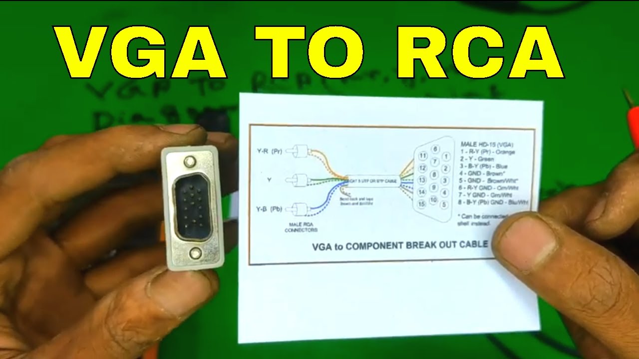
20.11.2021 · Rca to Vga Wiring Diagram- wiring diagram is a simplified within acceptable limits pictorial representation of an electrical circuit. 96 $ 43 . Name. Aug 12, 2019 · VGA uses separate wires to transmit the three color component signals and vertical and horizontal synchronization signals. 6 out of 5 stars. 3. Genuine 2008 Dodge Part # 55111313AC … Circuit diagram for basic alarm with delayed trigger: Alarms: Feb 09, 2010-1: General purpose portable DC power supply using rechargeable C cells : Power: Feb 05, 2010-1: PCB board tester and RF detector circuir diagrams: Test: Feb 09, 2010-1: Alarm circuit to remind you to turn off your DMM (digital multimeter) Test: Jan 31, 2010-2: Circuit to enable cycling a string of … The Raspberry Pi is no slouch when it comes to video. if you have no HDMI plugged in, and you connect the RCA, it should output via RCA. 0-2019 has killed hdmi output (Hirsuite Raspberry Pi 4) This is a workaround for the problem mentioned in the title. When configured correctly, you can use this to connect to an older tv without needing HDMI converter boxes. Raspberry Pi 400 … The circuit is powered from a USB cable and works for resolutions up to 1600 ... HDMI-to-VGA (HDMI2VGA) Converter Block Diagram (Simplified Schematic: All ...
Also if the rgb lines are in-cased in shields, you will have to modify the wiring diagram. Tip Question Comment. Step 3: I2c Interface. Diy hdmi to lvds. More info:::: the LCD in my car has LVDS input I need to convert the LVDS inputBecause it is the DIY product, so sometimes there may be the compatibility problem. 3" LQ133M1LW02 1920x1080 LED Screen. 30.01.1997 · VGA Video Graphics Adapter VHDL VHSIC Hardware Description Language VHF Very High Frequency (30-300 MHz) VHS Video Home System VHS-C Video Home System Compact VHSIC Very High Scale Integrated Circuit VI Virtual Instrument VIA Versatile Interface Adapter VINES VIrtual NEtwork Software (Banyan) VLB VESA Local Bus (VL bus) VL bus … Rs232 to rs485 cable pinout diagram at pinoutsru for rs232 to rs485 wiring diagram image size 836 x 500 px and to view image details please click All the UARTs pins are TTL compatible, including TD, RD, RI, DCD, DSR, CTS, DTR and RTS, so direct usage of pinouts for connecting to serial port is not possible. This is the simplest solution to connecting the two computers. …
Rf signal amplifier circuit diagram. 2. 1 circuit diagram of class B push pull amplifier 6 1. 4ghz rf transmitter AN282 MAX2472 HP-E4433B DSSS transmitter complete circuit diagram for a PA amplifier circuit diagram of 2. If I fit a splitter, the picture breaks up!" A. LM386 audio probe amplifier is an essential tool for troubleshooting audio stages in audio related circuits such as …
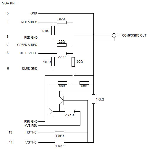
This circuit is designed for converting normal VGA signals standard RGB signals and composite sync signal. The circuit is quite simple, because RGB signal ouput ...


0 Response to "36 vga to rca converter circuit diagram"
Post a Comment