37 accelerator pedal position sensor wiring diagram
Mitsubishi Pajero Io Workshop Manual Wiring Diagrams Repair Manuals Grand Vitara Suzuki Jimny . 15 Toyota 3rz Engine Wiring Diagram Engine Diagram Wiringg Net Toyota Engineering Toyota Hilux . Kia Sorento 2006 Model D4cb Accelerator Pedal Position Sensor Electrical Diagram Google Search Mitsubishi Outlander Outlander Diagram This code indicates that your PCM has detected that your throttle body plate is stuck in the closed position. Your PCM monitors and controls your throttle actuator system through one or multiple throttle position sensors in your vehicle. If your PCM has failed to detect movement from your throttle actuator motor, it may trigger a P2112 code.
6 Pin Accelerator Pedal Position Sensor Wiring Dia... Draw Wiring Diagrams - Software To Draw General Wi... Bush Plane Engine Diagram - What Materials Are Pla... Cherokee 1988 Electric Diagram : 1988 Jeep Wiring ... Panel Networking Admin Interface Guide / Network D... Emotional Intelligence Handouts - 1 /

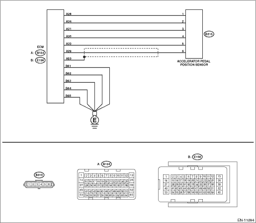
Accelerator pedal position sensor wiring diagram
Followup from the Pelican Staff: The throttle position sensor is in the throttle, not at the pedal. At the pedal is the accelerator pedal position sensors. A lot of times it is a faulty throttle housing. Just be sure the wiring from the DME to the throttle housing is OK, as it has often been faulty when I tested it. - Nick at Pelican Parts The ECM meters the fuel output of the injectors using pulse width signals. It varies the pulse width based on input signals. Inputs to the ECM include: air intake volume using mass airflow sensor signal, ambient and coolant temperature signals, accelerator pedal signal, crankshaft and camshaft position signals, knock sensor signals. The core is then surrounded by a coil of wire. One wire is connected to the magnet and the other to the e ABS wiring harness. The sensor is placed close enough to the tone ring to induce magnetic flux onto the tone ring. The "air gap" between the sensor and tone ring is critical as the magnetic flux is not very strong.
Accelerator pedal position sensor wiring diagram. 6 Pin Accelerator Pedal Position Sensor Wiring Dia... Draw Wiring Diagrams - Software To Draw General Wi... Bush Plane Engine Diagram - What Materials Are Pla... Cherokee 1988 Electric Diagram : 1988 Jeep Wiring ... Panel Networking Admin Interface Guide / Network D... Emotional Intelligence Handouts - 1 / P1288 - Accelerator Pedal Position Sensor 3 Circuit High Voltage P1300 - Ignitor Circuit P1305 - Ignition Coil 2 Primary Feedback Circuit P1310 - Ignition Coil 3 Primary Feedback Circuit P1315 - Ignition Coil 4 Primary Feedback Circuit P1320 - IC 4X Reference Circuit Intermittent ... Throttle control unit, engine management system (petrol) 10: F8: Accelerator Pedal Position Sensor, A / C Compressor Clutch Relay, Fuse / Relay Box Cooling Fan: 10: F9: Sound signal: 15: F10: Rear window washer pump motor: 10: F11: Engine Management, Glow Plugs Heating / Air Conditioning System Crankcase Ventilation Heater (Diesel) 20: F12 ... Additionally, the Cat C16 7CZ engine wiring diagrams are included in high resolution PDF format. This is a complete OEM reference for professional mechanics to service and repair the engine. ... Accelerator Pedal (Throttle) Position Sensor Circuit - Test Air Inlet Shutoff Circuit - Test ATA (SAE J1587 J1708) Data Link Circuit - Test ...
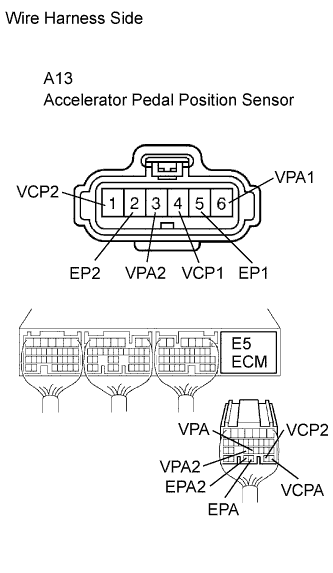
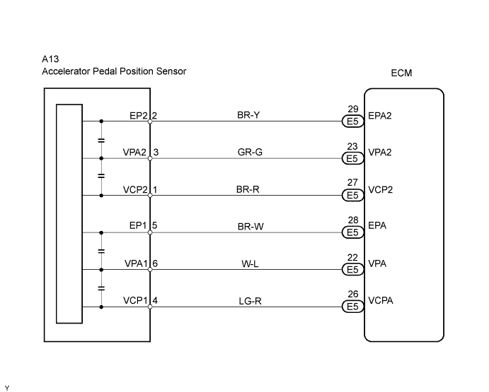
1992 Cadillac Seville - Where is the obd connector on the 1992 seville- question about Cars & Trucks Throttle / Pedal Position Sensor / Switch "D" Circuit High Input - APP sensor - Open in EPA circuit - ECM. Comes on. DTC stored. ES-293. P2125. Throttle / Pedal Position Sensor / Switch "E" Circuit - APP sensor - ECM. Comes on. DTC stored. ES-293. P2127. Throttle / Pedal Position Sensor / Switch "E" Circuit Low Input - APP sensor - Open in VCP2 ... 6 Pin Accelerator Pedal Position Sensor Wiring Dia... Draw Wiring Diagrams - Software To Draw General Wi... Bush Plane Engine Diagram - What Materials Are Pla... Cherokee 1988 Electric Diagram : 1988 Jeep Wiring ... Panel Networking Admin Interface Guide / Network D... Emotional Intelligence Handouts - 1 / Get ready with these few tips for the release of Resident Evil 3 and Resident Evil Resistance! April 10, 2020. admin. I give you his tips for surviving in Raccoon City by playing as Jill, a Survivor…. Tips - How to.
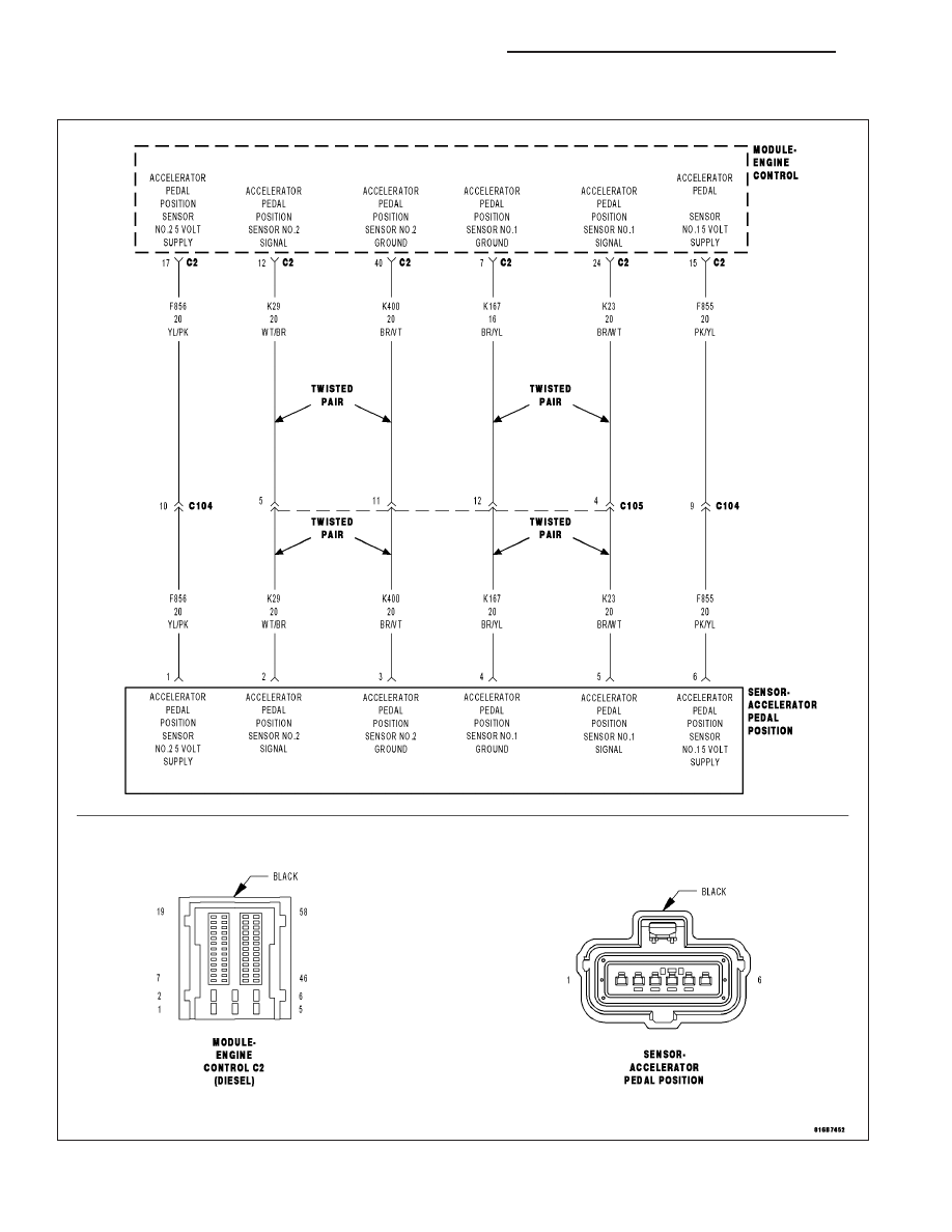
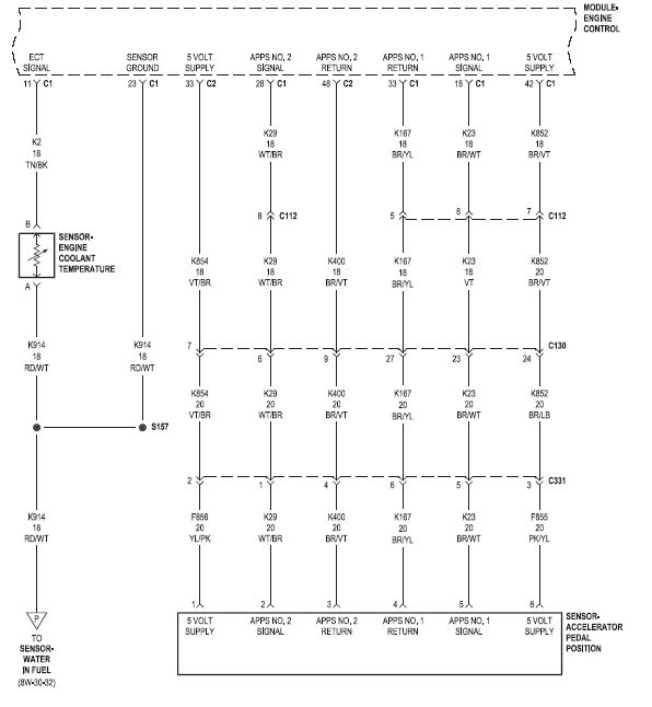
The electronic throttle control (ETC) system is a system that electrically opens the throttle valve. The parts of the ETC system, which consist of accelerator pedal position (APP) sensors, electronic throttle actuator, and throttle position (TP) sensors, are interconnected and controlled by a control module, which is usually the powertrain control module (PCM). Engine Mechanical. Camshaft & Valve Mechanism. Crankcase Ventilation. Cylinder Block & Oil Pan. Cylinder Head & Rocker Cover. Engine & Transmission Mounting. Engine Gasket Kit. Fan,Compressor & Power Steering Belt. Front Cover,Vacuum Pump & Fitting. Joined: Jun 2016. RE: Throttle Position Sensor Problems - Solving them. I was taught that all wire repairs should be soldered with a linesman's knot and heat shrinked at a minimum, with adhesive heat shrink used on exterior connections. Butt connectors should be used just to get you from point A to B for a proper repair. The throttle position sensor reads the position of the gas pedal in your Engine Control Unit. Here are some signs indicating your throttle position sensor needs to be replaced: if your engine stalls or misfires, if the engine is in poor performance; if there is a loss of power; if the transmission does not shift correctly.
Fuses and relays Volvo XC90 (C; 2002 - 2014) 12.11.2021. The first generation of the luxury crossover Volvo XC90 was presented in 2002. Together with the S60, V70 and S80 models, it is built on the P2 platform. For its time, it became the largest among the crossovers produced by the company. In this material, we will analyze in detail the fuse ...
Eautorepair.net redraws factory wiring diagrams in color and includes the component, splice and ground locations right in their diagrams. That saves a lot of time because you don't have to refer back to the component locator or circuit locations. Alldatadiy.com, on the other hand, uses the factory diagrams.

A problem with the throttle actuator control system may cause the PCM to restrict its operations. This is known as the "limp home mode" or a "fail-safe" position, where the engine is held at idle or has limited power to prevent unwanted acceleration. Note: The definition of code P2111 may be different depending on the vehicle manufacturer.
Accelerator pedal position sensor ground wiring. Thread starter Kmoton; Start date Nov 20, 2021; Nov 20, 2021 #1 K. Kmoton Junior Member. Joined Nov 20, 2021 Posts 1 Reaction score 0 ... Wiring diagram symbols. Latest: Jimijet; Today at 1:54 AM; Tech Info. Fix a flat. Latest: Randy Grant; Today at 1:39 AM; Exterior. Members online. Hemi 808 ...
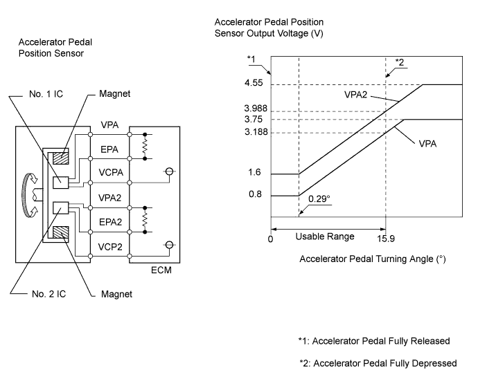
If the "Accelerator Pedal Position [%]" is based on the Voltage output from the variable resistor, then when in Cruise the Voltage will be fixed at the idle Voltage except if the driver presses it down again. (In contrast, the "Throttle Opening Angle [%]" is probably the Throttle Position Sensor signal which corresponds to the throttle plate ...

When the ignition SW is turned on and the brake pedal is pressed (Stop lamp SW on), if the stop light circuit is open, the current flowing from TERMINAL 7 of the light failure sensor to TERMINALS 1, 2 changes, so the light failure sensor detects the disconnection and the warning circuit of the light failure sensor is activated.
Fault code troubleshooting and Signature/ISX CM570 color wiring diagram are included. Topic list: Introduction. Engine Identification Engine Identification Engine Diagrams. Familiarization ... Accelerator Pedal or Level Position Sensor Circuit Unswitched Battery Supply Circuit Brake Pedal Position Sensor Brake Pedal Position Sensor Circuit ...
6 Pin Accelerator Pedal Position Sensor Wiring Dia... Draw Wiring Diagrams - Software To Draw General Wi... Bush Plane Engine Diagram - What Materials Are Pla... Cherokee 1988 Electric Diagram : 1988 Jeep Wiring ... Panel Networking Admin Interface Guide / Network D...

How to Test Crankshaft and Camshaft sensors 1 Accelerator Pedal Position Sensor How we rebuilt our Chevy Small-Block V-8 engine | Redline Rebuilds Explained - S1E2 How To: Remove\\Install A LS Oil Pump Install. (While Engine IS Still In Car.) ... V6 wiring diagram and connectors H002 11 VN Model (from Oct 1989) & VP Model V6 wiring diagram and ...

6 Pin Accelerator Pedal Position Sensor Wiring Dia... Draw Wiring Diagrams - Software To Draw General Wi... Bush Plane Engine Diagram - What Materials Are Pla... Cherokee 1988 Electric Diagram : 1988 Jeep Wiring ... Panel Networking Admin Interface Guide / Network D... Emotional Intelligence Handouts - 1 /
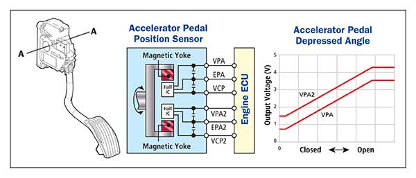
The ECTS is responsible for controlling the throttle valve opening. When the accelerator pedal is pressed, the accelerator pedal position (APP) sensor sends a signal to the PCM indicating how much power the engine needs to produce. The PCM then commands the throttle plate to open accordingly.

The core is then surrounded by a coil of wire. One wire is connected to the magnet and the other to the e ABS wiring harness. The sensor is placed close enough to the tone ring to induce magnetic flux onto the tone ring. The "air gap" between the sensor and tone ring is critical as the magnetic flux is not very strong.

The ECM meters the fuel output of the injectors using pulse width signals. It varies the pulse width based on input signals. Inputs to the ECM include: air intake volume using mass airflow sensor signal, ambient and coolant temperature signals, accelerator pedal signal, crankshaft and camshaft position signals, knock sensor signals.
Followup from the Pelican Staff: The throttle position sensor is in the throttle, not at the pedal. At the pedal is the accelerator pedal position sensors. A lot of times it is a faulty throttle housing. Just be sure the wiring from the DME to the throttle housing is OK, as it has often been faulty when I tested it. - Nick at Pelican Parts


0 Response to "37 accelerator pedal position sensor wiring diagram"
Post a Comment