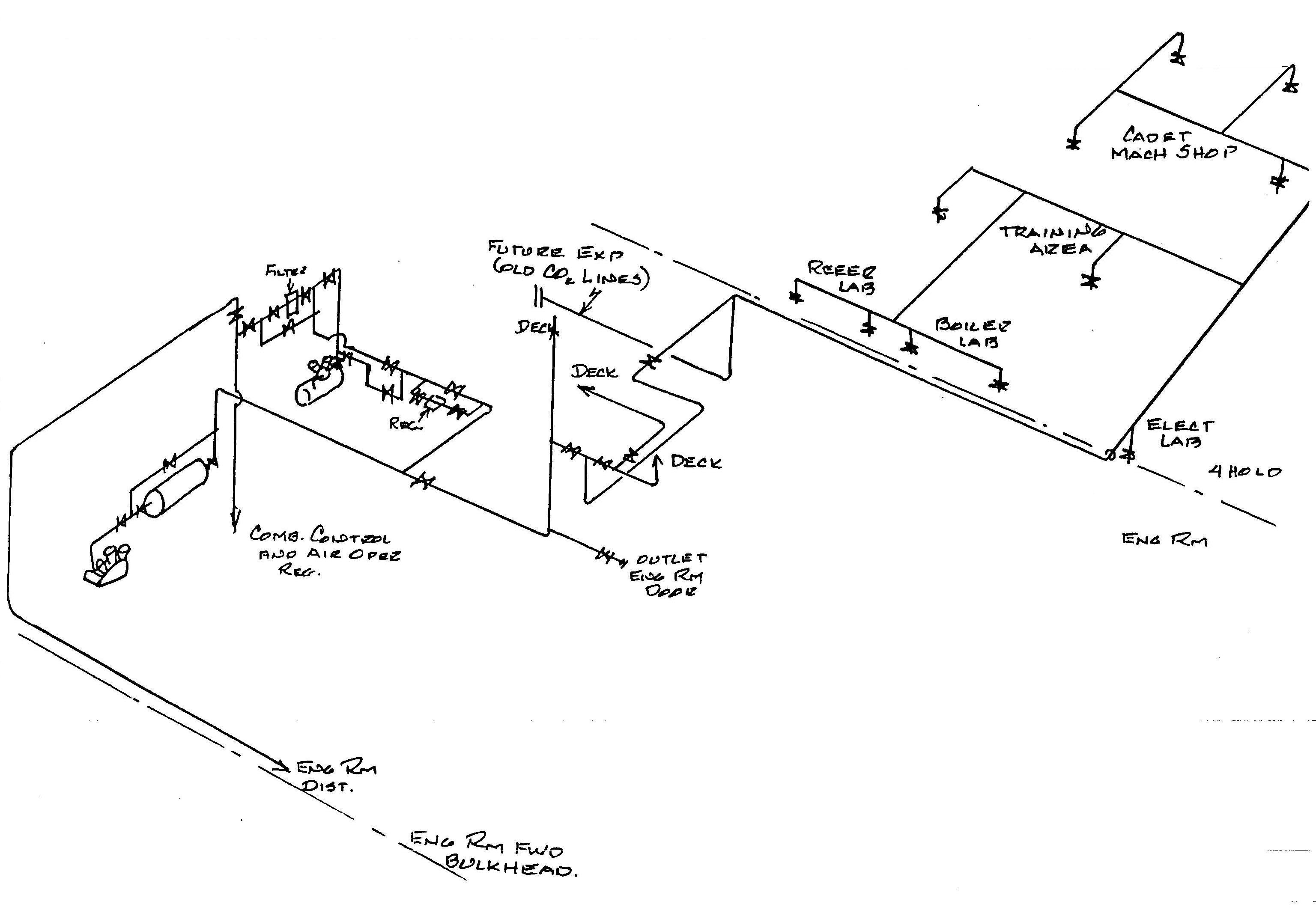
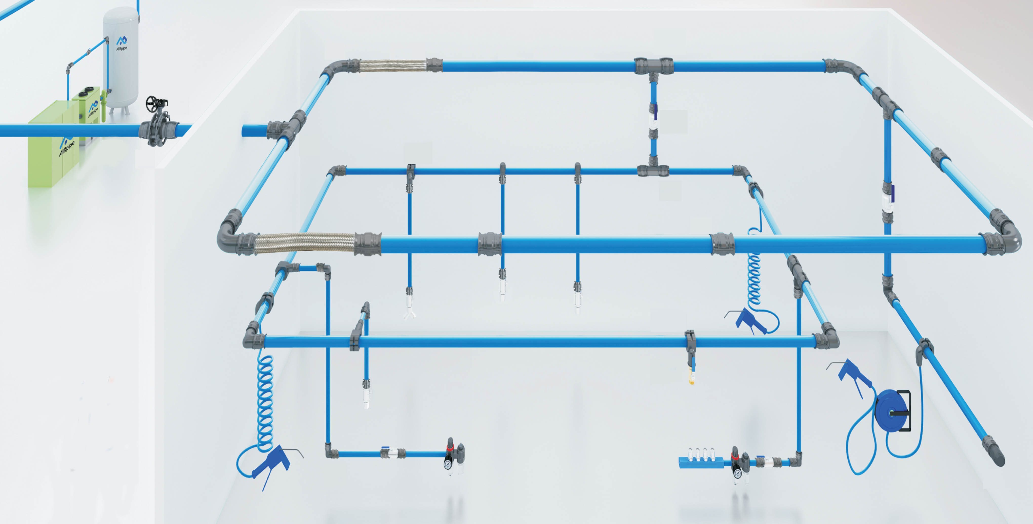
37 compressed air system piping diagram
AIR SYSTEM PIPING DIAGRAMS 121 Trailer Air Systems Tri Axle Trailer ABS Exempt 2 Tanks 3 Valves Tri Axle Trailer ABS Exempt 2 Tanks 2 Valves Phone 602 253-1007 Page 75 Fax 800 222-2334 AIR SYSTEM PIPING DIAGRAMS 5 Port 2 Way Valve Manual Lift Axle Trailer Application. These diagrams are provided for basic identification only. In a compressed air system, similar things happen within the piping scheme. Valves, tees, elbows, pipe reducers, filters, etc. are common items that will affect the flow. Let's look at a scenario with the EXAIR Digital Flowmeters. In the instruction manual, we require the meter to be placed 30 pipe diameters from any disruptions.
There are many reasons why you might want to blow out sprinklers with an air compressor. One of the best ways to end a long winter is by creating lovely summer mayhem.! An air compressor will also help get rid of built-up sediment in your sprinkler system that can cause clogs. Before blowing out your […]
Compressed air system piping diagram
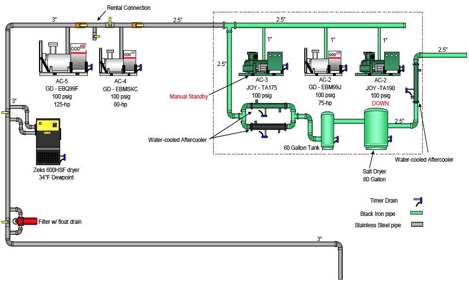
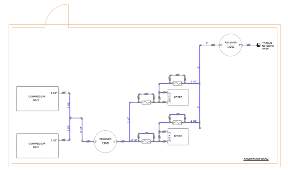
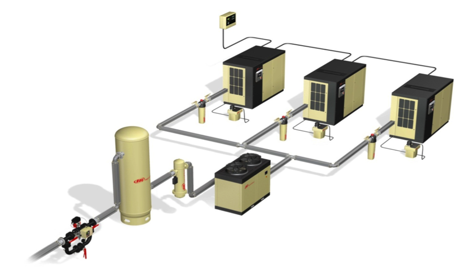
Sep 17, 2021 — Piping diagram showing Gardner Denver Air compressors hooked together. Before designing your compressed air piping system, its critical facility ... JOB KNOWLEDGE: Familiarization of general carpentry, structural and mechanical systems, including domestic hot and cold water piping systems, wastewater piping systems and vent stacks, storm water management systems, , water treatment facilities, swimming pool equipment, fire suppression systems, compressed air systems, and irrigation systems ... Improve your understanding of the design, installation, and operation of plumbing systems, including municipal and domestic water supply, waste and vent, storm water, specialty gases, and equipment. Learn how to comply with the codes related to pipe sizing and layout, and coordinate your plumbing design and installation with the work of other consultants and contractors.
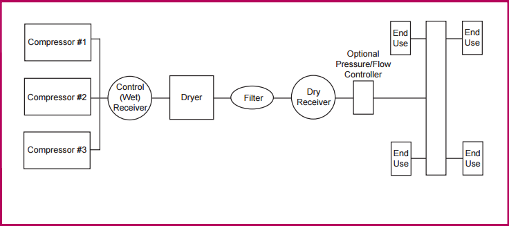
Compressed air system piping diagram. (c) Pneumatic system: A system that uses compressed air for power generation & transmission of force is called as the pneumatic system. Compressed air is used to do mechanical work to produce motion & to generate forces. 2. Define pump and state the purpose of the pump in hydraulic system & classify pumps. Answer: Aug 25, 2019 — An air compressor piping diagram is created by connecting an air compressor to any end-user tool through the use of a pipe. Piping Calculations Manual This on-the-job resource is packed with all the formulas, calculations, and practical tips necessary to smoothly move gas or liquids through pipes, assess the feasibility of improving existing pipeline performance, or design new systems. Piping Calculations Manual Contents: Water Systems Piping * Get Images Library Photos and Pictures. Air Compressor An Overview Sciencedirect Topics Ac Compressor Schematic 1948 Ford Dash Wiring Diagram For Wiring Diagram Schematics Schematic Diagram Of The Compressed Air System Download Scientific Diagram Compressed Air Piping Distribution Systems Compressed Air Best Practices
More than 2000 vector piping and instrumentation diagram symbols are provided including ductwork symbols, valves, pumps, motors, blowers, chillers, tanks, logistics, production process symbols, HVAC symbols, and much more. Lifelike symbols help create presentation-quality piping and instrumentation diagrams. An air-source heat pump (ASHP) is a system that transfers heat from outside to inside a building or vice versa. Under the principles of vapor compression refrigeration, an ASHP uses a refrigerant system involving a compressor and a condenser to absorb heat at one place and release it at another. by Ashlin June 24, 2021. June 24, 2021. 0 61. Adaptive control can be described as an auto-correcting form of control, it is composed of both feedback and optimal control. An adaptive control system would... Control System Instrumentation. 37 rational numbers venn diagram worksheet; 41 compressed air system piping diagram; 37 orbital diagram of fe; 40 pbs 3 wiring diagram; 39 1g dsm wiring harness diagram; 39 how to create a venn diagram in powerpoint; 41 venn diagram comparing dna and rna; 42 detached garage sub panel wiring diagram; 41 acorn stair lift parts diagram; 42 ...
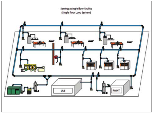
Tips for an Efficient Compressed Air Piping System Layout — Tips for an Efficient Compressed Air Piping System Layout. Implementing a couple of best ... In a separate assessment example, the system was actually equipped with dryers sized appropriately for the upstream compressor demand. However, the piping infrastructure forced the majority of compressed air through dryer 1. The result: the dryer was not performing to standard. Compressed air will follow the path of least resistance. May 15, 2020 — To manage your costs, you must pay attention to various aspects of your piping system, including the layout, installation and maintenance. If ... It shows compressed air controlled by three valves (VLV05, VLV07 and VLV08). And when the solenoid (SOL06) is energized while the cylinder (CYL03) is retracted, the system starts cycling to extend and retract the cylinder. Supply air flowing through VLV08 and SOL06 provides pilot air to the directional control valve (VLV05).
When you attach a compressor to an end-user device through a pipe, you have created your very own air compressor piping diagram. This is all very simple when we speak about it in such terms, but it can be more complicated to create. To create your own air compressor piping diagram, you need to know your project's requirements.
In many facilities, compressor systems often get little attention from engineering ... Generally, every facility has a fire system schematic piping drawing ...

Figure 2: Vacuum and compressed air piping system components in a hospital are shown. A main line valve is provided as an option if the source valve is located outside the building. Courtesy: SmithGroup
General Rules for air compressor piping system — You need some type of piping system for the compressed air to travel and run the operation that connects ...

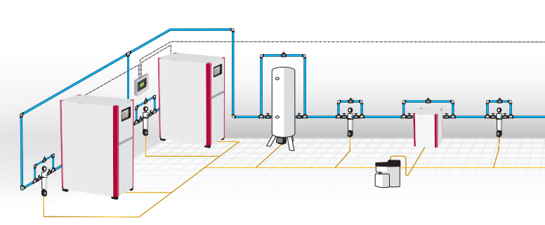
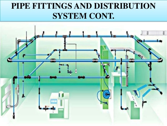
May 12, 2021 — About Compressed Air Piping Systems ... Your compressed air distribution system consists of a series of pipes that convey compressed air from the ...
eCompressedair offers a comprehensive range of Aftermarket Parts & Kits for Ingersoll Rand Compressors. All of our aftermarket replacement compressor kits and parts meet or exceed the original OEM specifications. Buy Now!
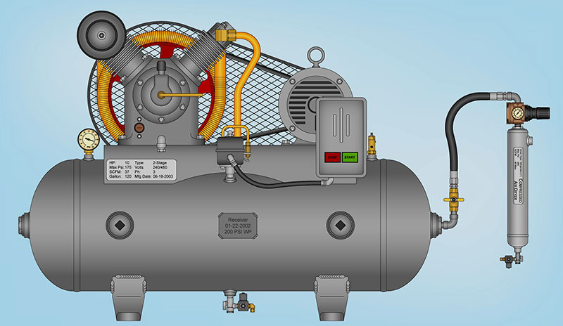
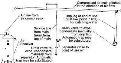
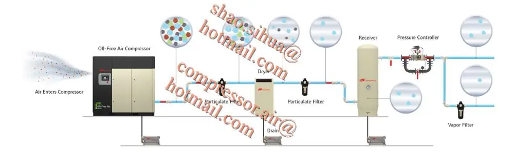
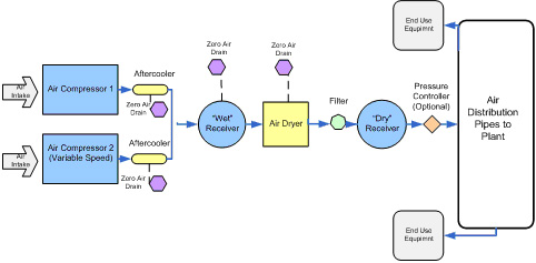
The compressor should have a moisture separator. The dryer should have a pre-filter and an after filter. And the receivers should be sized based on the CFM of the compressors. Below is a typical example of an air compressor setup diagram. Air Compressor Maintenance Plan

The air compressor pump at the receiving station can suck or blow air. When it sucks, it pulls canisters along the tube toward it; when it blows, it pushes the canisters in the opposite direction. Just as a vacuum cleaner is limited by the suction power of its electric motor , so pneumatic transport tubes are limited in what they can carry, how ...
A pneumatic system is a machine that uses pressurized air to control movements such as holding, moving, and forming materials together. Pneumatic equipment relies primarily on large amounts of compressed air to perform. It is important for many machines to carry and maintain constant air production.

The bladder occupies the lower section of the tank while the top part is filled with compressed air. An air inlet valve at the top of the tank allows you add pressure the tank. The pressure tank is connected to a pressure switch, pump, and a check valve. The system is powered by electrical power with a dedicated circuit breaker.

HVAC (heating, ventilation, and air conditioning) plans refer to the drawings made by specialized engineers that include all the details needed to create, set up, and maintain the heating and cooling system in a building.. The HVAC plans are quite important and are developed once the building's floor plans have been completed. The engineers use their expertise to develop the most effective and ...

Rotary screw air compressors are pressurized systems, comprised of many interconnected components that work together to compress air. Air and oil are both important aspects of a rotary screw air compressor system. Compressed air is the end goal, which requires the use of atmospheric air, but the oil is just as important.
Air Compressor Piping Diagrams And Tips. November 20, 2021. An air compressor generates power in the form of air pressure, and for an air compressor to work efficiently it requires a certain unit. This unit is the piping , glue that holds this intricate system together. Unfortunately, setting-up seems rather easier said, than done.

I emptied the air compressor and the aux tank to start fresh. I started by opening the regulator on the air compressor all the way so the aux tank can fill quickly. Aux tank only filled to 80psi and my air compressor filled to 125 psi (max) then turned off. My air compressor will kick on if it drops to 90psi.

When the chilled water system is off, the chilled water can reach ambient temperatures. In a building with no air conditioning, the temperature can be in the 80 to 90 F range. If the chilled water piping is located outdoors, then the temperature of the chilled water can exceed 100 F, depending on the location.

Reliable compressed air systems help keep things safe and operational. For example, a roller coaster's power gates, brakes and other critical safety features all require compressed air to maintain their reliability during use. The hydraulic launch systems needed for certain rides also rely on air compressors to provide stable air flow. 6.

Shop Air Piping Layout Diagrams. As we all know, compressed air is a key element in everything we do in the shop. And the quality of the paint job on ...
View our cycling flow schematic chart and diagram to see how it operates and the process steps of the cycling dryer operation.
An efficient and simple way to calculate the pressure loss in a piping system is the "Equivalent Pipe Length Method". 1. Make a Diagram of the Piping System. Make a diagram where the system is structured with nodes as shown below. In the very simply circulating system used in this example the first node (0) is the pump.
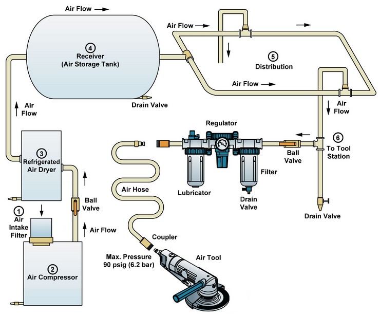
Here you have your air compressor plugged into the mains, (preferably by your garage door) that will be connected to your piping with a flexible hose attached straight to a filter before entering the piping system, the air can then pass through a regulator before entering the air hose reel and into the tool for your application.
Compressed air is in a key component in many pharmaceutical manufacturing operations. Air power is used in processes such as tablet manufacturing, cleaning and drying, transporting products, packaging and more.1 Because compressed air has such close proximity to products, extremely high air purity is required. Increasingly stringent regulations on purity have many pharmaceutical manufacturing ...

Improve your understanding of the design, installation, and operation of plumbing systems, including municipal and domestic water supply, waste and vent, storm water, specialty gases, and equipment. Learn how to comply with the codes related to pipe sizing and layout, and coordinate your plumbing design and installation with the work of other consultants and contractors.
JOB KNOWLEDGE: Familiarization of general carpentry, structural and mechanical systems, including domestic hot and cold water piping systems, wastewater piping systems and vent stacks, storm water management systems, , water treatment facilities, swimming pool equipment, fire suppression systems, compressed air systems, and irrigation systems ...

Sep 17, 2021 — Piping diagram showing Gardner Denver Air compressors hooked together. Before designing your compressed air piping system, its critical facility ...


0 Response to "37 compressed air system piping diagram"
Post a Comment