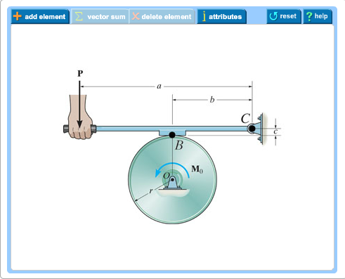
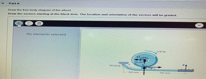
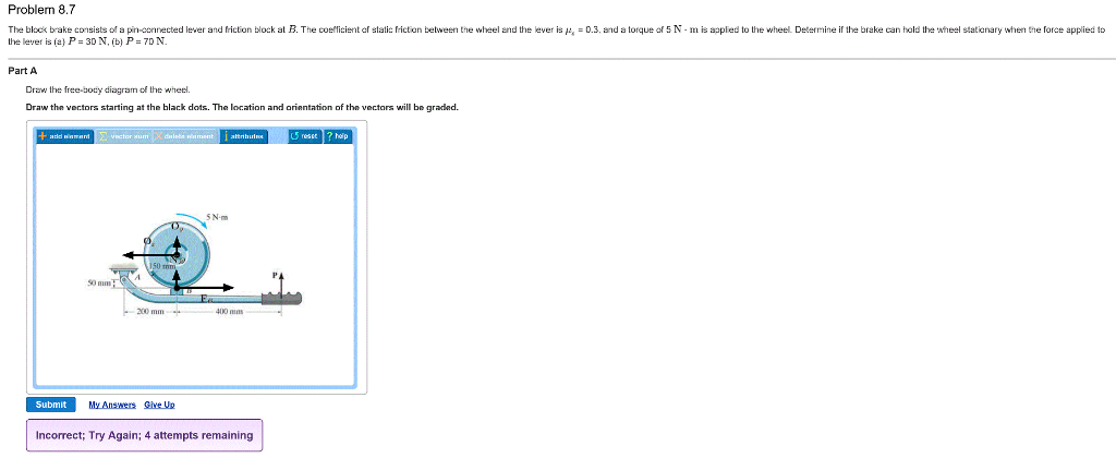
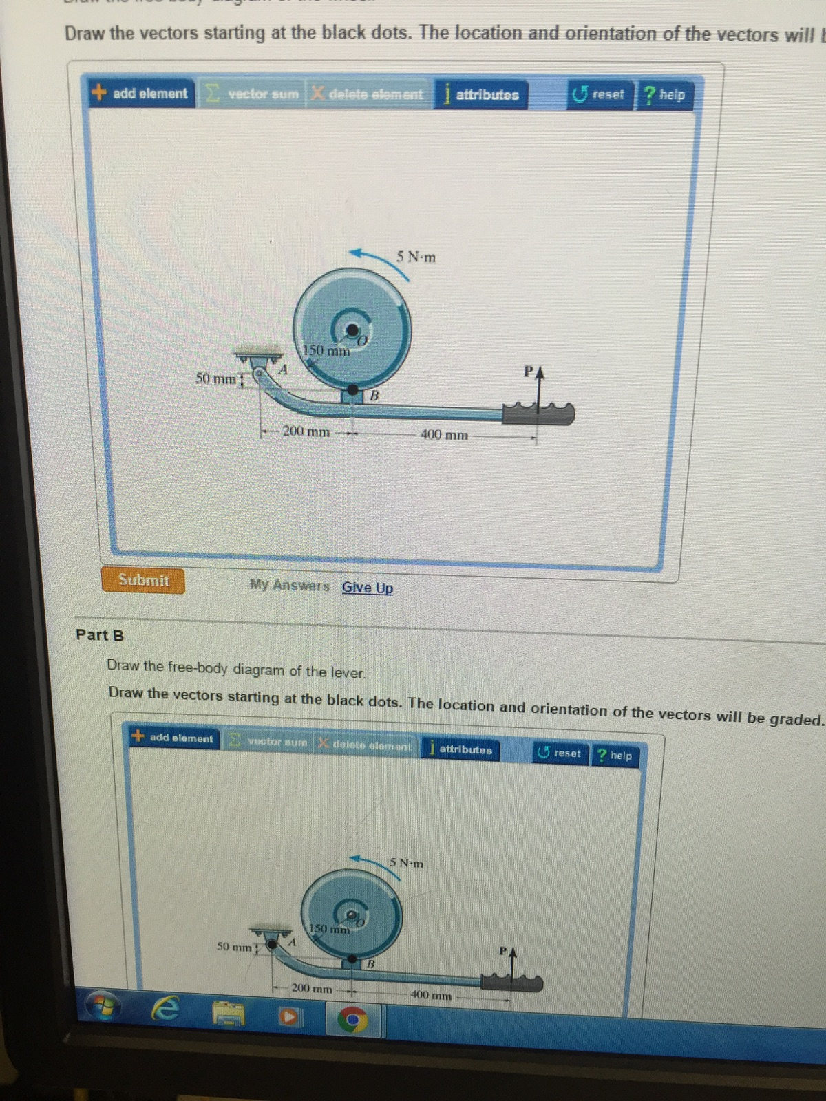
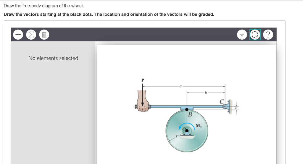
37 draw the free-body diagram of the wheel.
Free-Body Diagram 4 - 4 The first step in the static equilibrium analysis of a rigid body is identification of all forces acting on the body with a free body diagram. • Select the body to be analyzed and detach it from the ground and all other bodies and/or supports. • Include the dimensions, which will be needed
Draw a sketch and free-body diagram showing the forces involved. The free-body diagram is similar to the no-slipping case except for the friction force, which is kinetic instead of static. Use Newton's second law to solve for the acceleration in the x-direction. Use Newton's second law of rotation to solve for the angular acceleration. Solution
a. Draw a free-body diagram of the forces acting on the cylinder, with vectors originating at the point of application. b. Determine the acceleration of the cylinder as it rolls down the incline. I= 2 3 MR2 d q

Draw the free-body diagram of the wheel.
http://www.physicshelp.caGO AHEAD and click on this site...it wont hurt.Free simple easy to follow videos all organized on our website
Problem 248 To close a gate valve it is necessary to exert two forces of 60 lb at opposite sides of a handwheel 3 ft in diameter. Through an accident the wheel is broken and the valve must be closed by a thrusting bar through a slot in the valve stem and exerting a force 4 ft out from the center. Determine the force required and draw a free-body diagram of the bar.
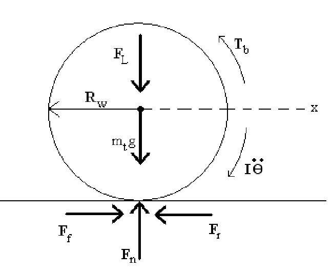
To draw the free body diagram proceed as follows. The following assumptions apply. 1. Wheel is rolling to right of page at constant velocity. 2. The wheel is on a straight level road. 3. The weight of the wheel is ignored. 4. The wheel is driven by a pure couple ie no resultant force due to driving mechanism. 5. The wheel does not slip. 6.
Draw the free-body diagram of the wheel..
Examples of drawing free-body diagrams. To better understand how to draw free-body diagrams using the 3 steps, let's go through several examples. Example 1. A box is pushed up an incline with friction which makes an angle of 20 ° with the horizontal. Let's draw the free-body diagram of the box. The first step is to sketch what is happening:
Draw a free-body diagram; be sure to include the friction of the road that opposes the forward motion of the car. A runner pushes against the track, as shown. (a) Provide a free-body diagram showing all the forces on the runner. ( Hint: Place all forces at the center of his body, and include his weight.)
Free Body Diagrams on a Loop‐the‐Loop Roller Coaster Draw the free body diagrams for a coaster at the boom and top of a loop and write the equaons for the net force. mg F net F N F net =ma = ma c The net force in the loop must be centripetal force F net = F N
Draw the free body diagram of the wheel and pulley assembly shown using the four step process presented in the chapter. These diagrams will be used throughout our study of physics. A point 1 at 12 oclock on inner circle. And y axis positive up. The selection of the body to sketch may be the first important decision in the problem solving process.
To draw a free body diagram, start by sketching a simple representation of the body you want to make the diagram of, like a square to represent a box. Next, draw arrows on the shape that show the forces acting on the object. For example, draw a downward arrow to signify the weight of the object, since gravity pulls the object down.
Draw the Free-body Diagram Of the Wheel. centripetal force problems - the physics hypertextbook the figure labeled "side view" draw and label arrows ing out of the coin to represent the forces acting on the coin you do not need to draw the mounting gas struts does this formula look right hey all i m just having some trouble mounting some gas struts to a canopy that i m building the door ...
A short video to show how to form an imaginary cut and draw a free body diagram of a simply supported beam with a point load.Related videos:Reactions of a Si...
To do this we draw a free body diagram for each unknown position in a system. Example: Simple Mass-Spring-Dashpot system. Consider a simple system with a mass that is separated from a wall by a spring and a dashpot. The mass could represent a car, with the spring and dashpot representing the car's bumper. An external force is also shown.
•Draw a free body diagram, showing all forces and their directions •Write equation of motion and derive transfer function of response x to input u chp3 15. ... wheel of mass m w (uniform mass distribution). Springs and dampers are connected to wheel using a flexible cable
Draw the free body diagram for the person when she is on the lowest position of the ride. Suppose that the wheel rotates at a speed that causes the person to experience three times her weight at that lowest point. Find the speed of the wheel under those conditions if the radius of the Ferris wheel is 6.0 m.
Below I've drawn a free body diagram of the wheel. The sum of the forces acting on the 5 holes should equal 650 kgf. The up pointing arrow is equal in magnitude to their sum. The applied torque, shown in blue, should be equal in magnitude to the torque generated by the left pointing force of friction in order for the wheel to rotate at a ...
Homework Statement Consider a biker riding on level ground as shown. She wants to have the maximum forward acceleration possible, which means experiencing the maximum horizontal force without her wheels slipping. Draw the free body diagram for the bike accelerating forward. Homework...
FREE-BODY DIAGRAMS (Section 5.2) 2. Show all the external forces and couple moments. These typically include: a) applied loads, b) support reactions, and, c) the weight of the body. Idealized model Free-body diagram (FBD) 1. Draw an outlined shape. Imagine the body to be isolated or cut "free" from its constraints and draw its outlined shape.
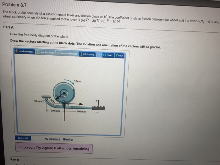
Transcribed image text: Draw the free-body diagram of the wheel. Draw the vectors starting at the black dots. Draw the vectors starting at the black dots. The location and orientation of the vectors will be graded. add elementvector sum X delete element I attributes U reset ? help 5 N m 150 mm 50 mm 200 mm Submit My Answers Give Up Incorrect ...
Newton/Euler: The next step is to draw the free body diagram of the wheel as shown below. Euler's equation can then be applied about point O to minimize the number of equations needed. Note that the moment arms for the two spring forces are computed assuming a small angle, θ.
The figure shows the free-body diagram of the wheel with the acting forces: the weight (green) and the pushing force F (red). ... as well as practice both drawing and interpreting free-body diagrams.
•5-1. Draw the free-body diagram of the 50-kg paper roll which has a center of mass at G and rests on the smooth blade of the paper hauler. Explain the significance of each force acting on the diagram.
Problems involving the kinetics of a rigid body rotating about a fixed axis can be solved using the following process. 1. Establish an inertial coordinate system and specify the sign and direction of (a G) n and (a G) t. 2. Draw a free body diagram accounting for all external forces and couples. Show the resulting inertia forces and couple
The free-body diagram for passengers at the top of a Ferris wheel is as shown. F N is the normal force of the seat pushing up on the passenger. The sum of the forces on the passenger is producing the centripetal motion, and so must be a centripetal force. Call the downward direction positive
(a) Draw the free-body diagram of the airplane. Deter-mine the reaction exerted on the nose wheel and the total normal reaction on the rear wheels (b) when T =0, (c) when T = 250 lb. W T A B 5 ft 4 ft 2 ft Solution: (a) The free body diagram is shown. (b) The sum of the forces: F X = B X =0 F Y = A Y −W +B Y =0. The sum of the moments about A ...
The car shown below is moving and then slams on the brakes locking up all four wheels. The distance between the two wheels is 8 feet and the center of mass is 3 feet behind and 2.5 feet above the point of contact between the front wheel and the ground. Draw a free body diagram of the car as it comes to a stop. Public Domain image, no author listed.
A free body diagram sometimes called a force diagram is a pictorial device often a rough working sketch used by engineers and physicists to analyze the forces and moments acting on a body. Draw the free body diagram of the wheel .









![Solved 4.5.2. [*] Draw the free-body diagram of the wheel ...](https://media.cheggcdn.com/media/925/925a721f-70cf-42fc-a955-d0b4ce1480a1/phpTWfXl5.png)
0 Response to "37 draw the free-body diagram of the wheel."
Post a Comment