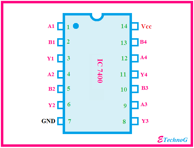
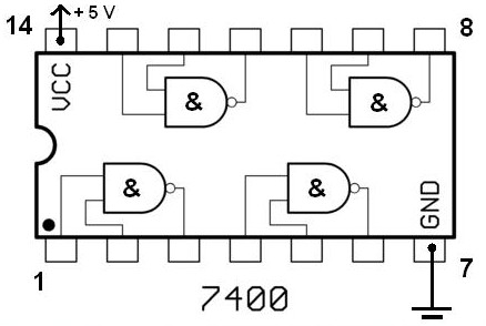
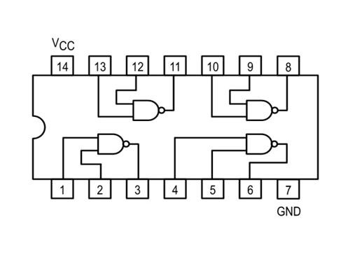
38 ic 7400 pin diagram
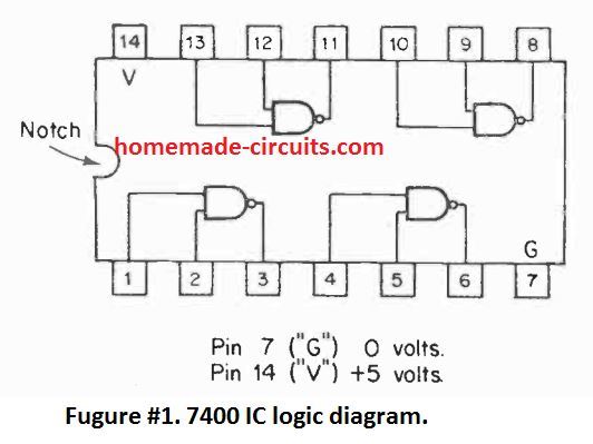
IC 7400, IC 7413 Specifications. The I.C.s 7400 and the 7413 are 14 -pin DIL ICs, or "14 pin Dual In Line Integrated Circuits", where pin 14 is the positive supply V+ and pin 7 is the negative, ground or 0 V pin.
IC-7400 transceiver pdf manual download. Icom IC-7400 Service Manual. Hf/vhf transceiver. Hide thumbs. Also See for IC-7400. Wiring Diagram. 84. Voltage Diagrams.
View online or download PDF (13 MB) ICOM IC-7400 User manual • IC-7400 Musical Instrument Amplifier PDF manual download and more ICOM online manuals. Icom IC-7400 | bolck diagram. for free by.

Ic 7400 pin diagram
The new Logi7400ic library provides a logical circuit appearance. Goal. This library aims to be a comprehensive 7400 series library for Logisim for designing logical circuits and for educational purposes. The library should be compatible both with original Logisim and logisim-evolution.
Other manufacturer's microphones have different pin assign-ments, and connection to the IC-7400 may The perfect match to your IC-7400 is the PS-125. This compact switching power supply is the For your information The diagram as at right shows the equivalent circuit of an external keypad and...
ICOM IC-7400 IC7400 IC 7400. If you have any question about repairing write your question to the Message board . Egy ultrahangos teljesítményelektronikában vannak az alábbi IC-k melyekről semmilyen adatlapot nem találtam: GF0803 - SMD 8 pin: ez 1 vezetékes (1-be, 1-ki) szintáttevő vagy...
Ic 7400 pin diagram.
7400-series integrated circuits. From Wikipedia, the free encyclopedia. Jump to navigation Jump to search. The first part number in the series, the 7400, is a 14-pin IC containing four two-input NAND gates.
Section 10 block diagram section 11 wiring diagram section 12 voltage diagrams. The divided signal at the DDS circuit (IC1101) is used for the marker signals with the After adjustment, disconnect the ammeter between the power supply and the IC-746PRO/7400.
7400 datasheet ic pin configuration circuit using nand gates capacitance meter with technical data draw the diagram of clock signal generator series For 7400 ic pin diagram orders, phone Note 5. Note 5: The input frequencies, f INare selected at the peaks and troughs of the frequency responses.
The IC 7400 consist of four NAND Gates. Pin diagram of IC 7400 explained here. Education. 4 days ago 7400 IC Chip Circuit Diagram 7400 package and pins showing pin outs . Here is some information about the 7400 Series TTL Integrated Circuits: PIN 2 PIN 3 PIN 1 PIN 4 PIN 5 PIN 6 PIN...
...IC7400) : Icom IC-7400 Instruction Manual PDF Adjusments Procedures Manual with schematics for Icom IC-7400 (IC 7400 IC7400) : Schematics for Icom After the remove, your RX/TX modification is ready to run on the german version of the IC-7400. RX: 30 kHz - 60 MHz 108 MHz - 174 MHz.
ℹ Download Icom IC-7400 Manuals (Total Manuals: 3) for free in PDF. Find more compatible user manuals for IC-7400 Transceiver device.
asked Mar 16, 2020 in Electronics by Richa01 (53.5k points). Draw the pin diagram of IC 7400. With a logic circuit, explain working of unlocked SR flip flop built using NAND gates. Draw its timing diagram and truth table.
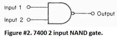
IC 7400 is fourteen pin Logic Gate IC. The IC 7400 consist of four NAND Gates. The NAND Gate is also called Universal Gate. The NAND gate has a total of three terminals, two inputs terminals, and one output terminal. All NAND Gates are independent.
7400 IC is a Quad 2-Input NAND Gate that contains four independent gates each of which performs the logic NAND function. 7400 IC Circuit Diagram. 7400 package and pins.
IC 7400 Pin Diagram, Circuit design, Datasheet. IC 7400 is fourteen pin Logic Gate IC. The IC 7400 consist of four NAND Gates. Operating Condition and Electrical Characteristics of IC 7400 described here. The Internal Structure and Pin Description of IC 7400 explained detail.
Keywords : 74xx, 7400, Integrated, Circuit, Ic, Pinout, Connection, Gate, Quad, Input, Output, Pals, NAND, GATE. Integrated Circuits > HM5144. Schematic Circuits > Sound Operated Switch.
First derived gate i.e. NAND gate by using diodes and transistors. Definition, Boolean equation, symbol, truth table, pin diagram and pin configuration of...
IC-7400 даташитов, IC-7400 datasheet, IC-7400 pdf, Icom - HF/VHF ALL MODE TRANSCEIVER Service Manual, IC-7400 описание, IC-7400 Даташит, цоколевка. даташит IC-7400 PDF ( Datasheet ). Datasheet Download - Icom.
This Article Discusses What is IC 7400, Specifications, Features, Circuit Diagram using NAND Gate, 7400 Family ICs, and Its Applications. The IC 7400 is a 14-pin chip and it includes four 2-input NAND gates. Every gate utilizes 2-input pins & 1-output pin, by the remaining 2-pins being power & ground.
7400 Siren - Basic Circuit - Circuit Diagram. Ttl 7400 Nand Gate Circuit Not Functioning. Page 9 Other Integrated Circuits Including Logic Gates. Pin On Electronics. 7400 Datasheet Pdf. Clock Signal Generator Using 7400 Ic Pcb. 2006 International 7400 Wiring Diagram.
IC 7400 : pin Configuration, Circuit, Specifications and. News Post. Details: IC 7400 Circuit Diagram using NAND Gate. News Post. Details: 7400 IC pinout diagram Integrated Circuits Elektropage.com. Related topics : Integrated Circuits > L165; 555-556 Timer info > 555 Astable...
From the diagram VCEsat vs. IC in any given 4 pin or 6 pin phototransistor data sheet, CTR , Vishay Semiconductors TTL Active Level High ( 7400 Series ) Vcc Vcc 12K 68 A A+B 7400 B , Active Level Low ( 7400 Series ) Vcc Vcc 12K 270 A 510 · A B Note: More parts , phototransistor optocouplers.
In this tutorial, code conversion circuits will be designed using SN7400 series of digital ICs. In the previous tutorial, the same series of 8: Pin Diagram of 7408 IC. The IC requires a supply voltage of 5V which can be tolerated up to 7V. The voltage at the inputs of AND gates must be 2V for high logic...







0 Response to "38 ic 7400 pin diagram"
Post a Comment