38 shear diagram cantilever beam
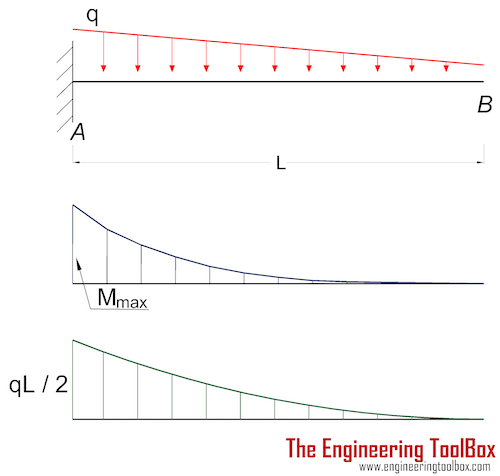
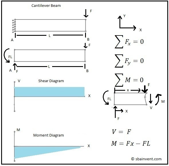
Sep 11, 2017 · BENDING MOMENT AND SHEAR FORCE DIAGRAMS OF A CANTILEVER BEAM. A shear force diagram is the graphical representation of the variation of shear force along the length of the beam and is abbreviated as S.F.D. A bending moment diagram is the graphical representation of the variation of he bending moment along the length of the beam and is abbreviated as B.M.D.
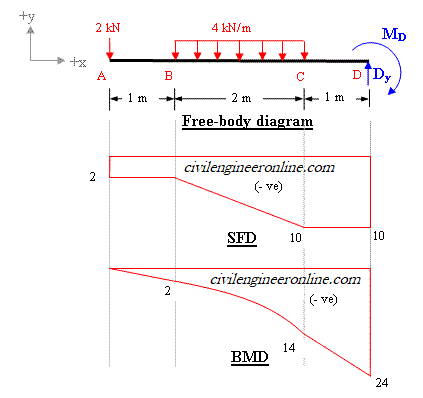
Shear Diagram. The shear at end A is −2 kN. This value is plotted at x = 0, Fig. 6-15 c . Notice how the shear diagram is constructed by following the slopes defined by the loading w . The shear at x = 4 m is −5 kN, the reaction on the beam. This value can be verified by finding the area under the distributed loading,
BEAM DIAGRAMS AND FORMULAS Table 3-23 (continued) Shears, Moments and Deflections 13. BEAM FIXED AT ONE END, SUPPORTED AT OTHER-CONCENTRATED LOAD AT CENTER

Shear diagram cantilever beam
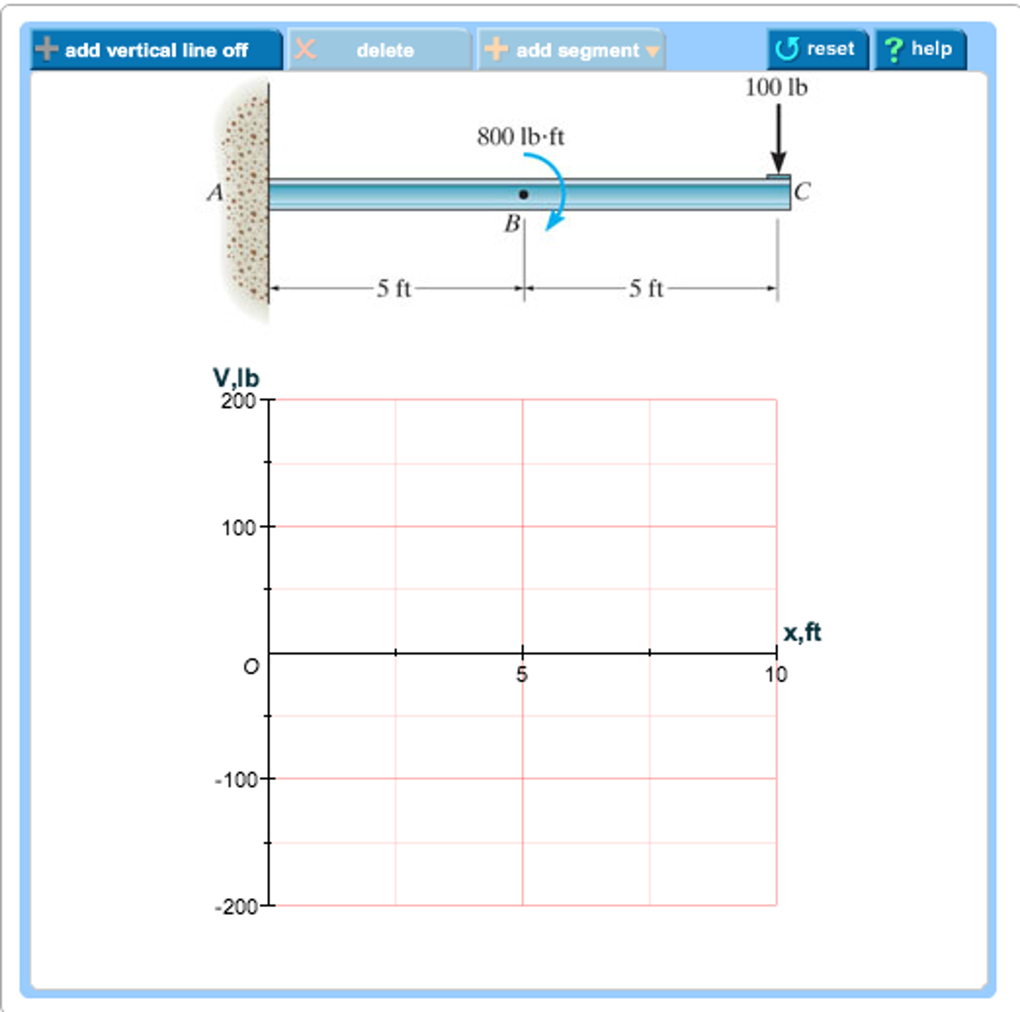
Use the Area Method to draw the LOAD DIAGRAM, SHEAR FORCE and BENDING MOMENTdiagrams for the cantilever beam.From Statics and Dynamics, Ruina and Pratap 7.1.10 Thecantilever beam shown in the figure is loaded with a concentrated load and a concentratedmoment as shown in the figure.Draw the shear force and the bend - ing moment diagram of thebeam. 100 N 50 N-m A 2m Pih roblem 7.1.10
S.F and B.M diagram (ii) A Cantilever beam with uniformly distributed load over the whole length When a cantilever beam is subjected to a uniformly distributed load whose intensity is given w /unit length. Shear force: Consider any cross-section XX which is at a distance of x from the free end. If we just take the resultant of all the forces on
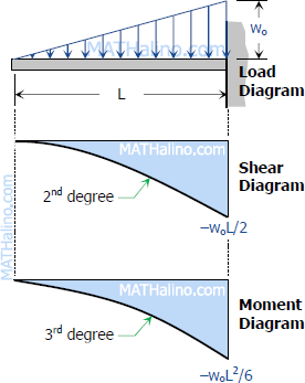
Problem 410 Cantilever beam carrying the uniformly varying load shown in Fig. P-410. [collapse collapsed title="Click here to read or hide the general instruction"]Write shear and moment equations for the beams in the following problems. In each problem, let x be the distance measured from left end of the beam. Also, draw shear and moment diagrams, specifying values at all
Shear diagram cantilever beam.
Problem 414 Cantilever beam carrying the load shown in Fig. P-414. [collapse collapsed title="Click here to read or hide the general instruction"]Write shear and moment equations for the beams in the following problems. In each problem, let x be the distance measured from left end of the beam. Also, draw shear and moment diagrams, specifying values at all change of loading
Draw shear force and bending moment diagram of cantilever beam carrying UDL and point loads. As shown in figure below; Solution. Shear Force. Let first draw shear force diagram. To draw shear force diagram, first find value of shear force at point C,B and A. Shear force will increase from left towards right.
Case 01. Shear Force and Bending Moment Diagram of Cantilever beam when point load is applied. From the figure we have the value of load at point A and point B. So let’s draws the shear force diagram with the help of these loading. Bending moment at point A is zero. Bending moment at point B= -2*2 = 4 KN-M. Bending moment at point C= -2*4-4*2 = 12 KN-M.
Shear Force (SF) and Bending Moment (BM) Diagram of Cantilever Beam The shear force at any section of a cantilever beam is the sum of loads between the section and the free end. The bending moment at a given section of a cantilever beam is the sum of moments about the section of all the loads acting between the section and the free end.
Shear Force And Bending Moment Diagram For Cantilever Beam With Two Equal Point Load Civil Snapshot. Sketch The Shear And Bending Moment Diagrams For Cantilever Beam Shown Given Following Parameters Omega A L Study. Draw The Shear Force And Bending Moment Diagrams For A Cantilever Beam Ab Carrying Uniform Load Of Intensity Q Over One Half Its ...
Shear force. It is a transverse force, one part of the beam exerts on the other part at any cross section. It is equal to the algebraic sum of all the transverse forces (including the reaction) either to the left or to the right of the cross-section. In the case of horizontal beams, shear force is the unbalanced vertical force on the left or ...
3.2 - Shear Force & Bending Moment Diagrams What if we sectioned the beam and exposed internal forces and moments. This exposes the internal Normal Force Shear Force Bending Moment ! What if we performed many section at ifferent values Of x, we will be able to plot the internal forces and bending moments, N(x), V(x), M(x) as a function Of position!
Draw the shear and moment diagrams for cantilever beam chegg. Assume the supports at a is fix c is roller and b is pin connections. Solved draw the shear diagram for the beam follow the si. 12 m 15 m12 m 8 kn 30 knm. No portion of this material may be reproduced in any form or by any means without permission in writing from the publisher.
Welcome to our free online bending moment and shear force diagram calculator which can generate the Reactions, Shear Force Diagrams (SFD) and Bending Moment Diagrams (BMD) of a cantilever beam or simply supported beam.
Shear stress at the end of cantilever beam when x l pared with scientific diagram a cantilever beam is subjected to distributed sh chegg shear stress at the end of cantilever beam when x l pared with scientific diagram cantilever beam udl and end bending moment 5 7 normal and shear stresses bending of beams informit.
This video explains how to draw shear force diagram and bending moment diagram with easy steps for a cantilever beam loaded with a concentrated load. Shear f...
basics of shear force and bending moment diagrams and sign conventions for shear force and bending moment in our recent posts. We have also discussed the concept to draw shear force and bending moment diagrams for a cantilever beam with a point load during our previous posts.
Jun 23, 2020 · Cantilever Beams Moments And Deflections. Solution To Problem 410 Shear And Moment Diagrams Strength Of Materials Review At Mathalino. Shear Force And Bending Moment Diagram For Cantilever Beam Civil Snapshot. Shear Force And Bending Moment Diagram For Cantilever Beam With Two Equal Point Load Civil Snapshot.
A cantilever beam is built into a rigid support at one end, with the other end being free, as shown in Fig.4.1(b). The built-in support ... The bending moment and shear force diagrams of the beam are composites of the V and M diagrams of the segments. These diagrams are usually discontinuous, or have discontinuous
SHEAR FORCE AND BENDING MOMENT DIAGRAM FOR CANTILEVER BEAM WITH POINT LOAD in Engineering Materials We were discussing meaning and importance of Shear force and bending moment and sign conventions for shear force and bending moment in our recent posts.
Variation of shear force and bending moment diagrams S.N Point Load UDL UVL Shear Force Constant Linear Parabolic Bending Moment Linear parabolic Cubic WORKED EXAMPLES 1) A cantilever beam of length 2 m carries the point loads as shown in Fig. Draw the shear force and B.M. diagrams for the cantilever beam. Shear Force Diagram S.F. at D, F D
Example - Cantilever Beam with Single Load at the End, Metric Units. The maximum moment at the fixed end of a UB 305 x 127 x 42 beam steel flange cantilever beam 5000 mm long, with moment of inertia 8196 cm 4 (81960000 mm 4), modulus of elasticity 200 GPa (200000 N/mm 2) and with a single load 3000 N at the end can be calculated as.
Lets derive an equation to represent the internal shear of this cantilevered beam with a uniformly distributed load along its span. We will then use that equ...
AMERICAN WOOD COUNCIL w R V V 2 2 Shear M max Moment x 7-36 A ab c x R 1 R 2 V 1 V 2 Shear a + — R 1 w M max Moment wb 7-36 B Figure 1 Simple Beam-Uniformly Distributed Load
Draw the shear and moment diagrams for the beam. . How to draw shear force and bending moment diagrams strength of note 1 you should not draw an extra discontinuity line at the point where the curve passes the x axis. What we're this 4.5 is nine halves. And 2 draw the shear force and bending moment diagrams.
Cantilever beam with point force at the tip. The force is concentrated in a single point, located at the free end of the beam. In practice however, the force may be spread over a small area, although the dimensions of this area should be substantially smaller than the cantilever length.
beam diagrams and formulas by waterman 55 1. simple beam-uniformly distributed load 2. simple beam-load increasing uniformly to one end. 3. simple beam-load increasing uniformly to center ... cantilever beam-uniformly distributed load 20. beam fixed at one end, free to deflect vertically but not rotate at other-uniformly distributed load.
Feb 04, 2021 · Cantilever beam using elements bending moment and shear force diagram 15 marks consider the cantilever how to calculate shear force diagrams how to calculate shear force diagrams. Cantilever Beams Moments And Deflections. Beam Stress Deflection Mechanicalc. Beam Stress Deflection Mechanicalc. Bending Moment And Shear Force Diagram For Cantilever.
![Cantilever Beam: Shear Force and Bending Moment Diagram [SFD BMD Problem 2] By Shubham Kola | Facebook](https://lookaside.fbsbx.com/lookaside/crawler/media/?media_id=257535155732524&get_thumbnail=1)
Cantilever beam: shear force and bending moment diagram [sfd bmd problem 2] by shubham kola | facebook









![[Ex. 07] Shear Moment Diagram Cantilever Beam Distributed Load Part I](https://i.ytimg.com/vi/qMk5IVKcZQM/maxresdefault.jpg)





0 Response to "38 shear diagram cantilever beam"
Post a Comment