39 fe-c phase diagram
1/ the value of the activity of a species in a phase acr (specie,phase) For example, for C in BCC_A2 with an activity of 0.2 add : acr (C,BCC_A2)=0.2. 2/ the value of the activity of a component ...
(D) Candidate phase diagrams with K = 2 and 3 fit points are shown for the Fe-Co-Ta system to illustrate the results of the phase diagram model. ( E ) The summary of 108 three-cation composition systems (gray points), including some duplicate systems from different print sessions.
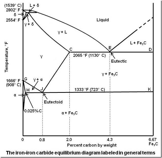
The temperature (in °C) of peritectic reaction in iron-carbon phase diagram is a) 1539 b) 1493 c) 910 d) 1175 -Two hypothetical metals A and B show limited solid solubility in each other in solid state. The invariant reaction of this system is given as follows: L (60%B) 400"a (30%) + (80%) 12- The invariant reaction of this system is a ...

Fe-c phase diagram
Difference between phase diagram and TTT diagram of steel. For a clear understanding of this diagram, it is better to understand the phase transformation of the Fe-Fe3C curve. The phase transformation diagram and TTT diagram has a major difference that you must understand. Phase transformation just describe continuous and equilibrium cooling ...
Hence, after annealing at 670 °C, irregular rod-like γ′-L1 2 phase, B2-structured Fe-Co phase and the lamellar-like structure consisting of parallelly elongated γ′ phase and B2 phase were formed in the ID regions (Figs. 10 and 5). In the meantime, the γ′-L1 2 precipitates in the DR region became coarser.
The largest phase field consists of austenite (γ-Fe), M 7 C 3 carbide and MX carbonitride on the phase diagram, where M means substitutional elements and X means a combination of carbon and nitrogen (C + N).
Fe-c phase diagram.
T SDW, T m, T c, T SG, and T SR denote the temperatures of spin-density wave (SDW) ordering, Eu-spin antiferromagnetic (AFM) ordering, superconducting transition, spin-glass (SG) reentrance, and spin reorientation (SR), respectively. For comparison, the inset shows the phase diagram of Eu (Fe 1 − x Ni x) 2 As 2 (adapted from Ref. ). Reuse ...
A system of magnetic molecules coupled to microwave cavities (L C resonators) undergoes the equilibrium superradiant phase transition.The transition is experimentally observable. The effect of the coupling is first illustrated by the vacuum-induced ferromagnetic order in a quantum Ising model and then by the modification of the magnetic phase diagram of Fe 8 dipolar crystals, exemplifying the ...
Phase diagram calculated with the symmetry-adapted 2-4-6 potential in Eq. for Fe (PM − pea) 2 (NCS) 2 and Fe (PM − pea) 2 (NCSe) 2 using negative values for the coefficients a and D. The horizontal arrow represents the pressure-induced high-spin, low-symmetry (HSls)-to-low-spin, high-symmetry (LShs) phase transition.
The ternary phase diagram of Fig. 5c calculated at T = 400 °C, highlights the formation of two-phase equilibria involving the metastable phase γ m: the γ m-γ equilibrium at low concentration ...
The phase diagram for the iron-carbon (Fe-C) system is shown below. Use it to answer the following questions. (2 points each) Compositien (at% Ch 20 1600 1538 C 2493 C 1400 2500 1394 C 1147 C 1200 2.14 4.30 Austenite 2000 1000F y+Fe C 912 C 1500 800...
Besides gadolinia-doped ceria, two Fe/Co-spinel phases are in equilibrium in agreement with the phase diagram. Moreover, a donor-doped GdFeO 3-based perovskite (Gd,Ce)(Fe,Co)O 3 showing electronic conductivity is formed. Due to these intense phase reactions, the composition of each individual phase is assessed for all composites and their ...
According to the Fe-Cr-Ni three-component alloy phase diagram shown in Figure 5(c), it can be concluded that the transformation from austenite into ferrite occurs when the temperature is increased in FSW. After welding, the formed ferrite is retained at high cooling rate.
TTT DIAGRAM 41. WHY - TTT & CCT DIAGRAMS ? • The phases martensite and bainite are non- equilibrium phase that do not appear in fe-fe3 c (iron-iron carbon) phase diagram • also strengthening treatment like hardening and tempering are non-equilibrium process. • In order to show the influence of varying cooling rates, that is time, on the ...
We investigated the phase diagram of NaxCo0.44Mn0.56[Fe(CN)6]0.90 in the entire Na concentration range of 0.00 ≤ x ≤ 1.60. We found that the compound shows an electron transfer (ET) phase transition in a wide x range of 0.19 ≤ x ≤ 1.38. The extended ET model well reproduces the variation of the [Fe2+(CN)6]4− and [F
c I-V curves and the corresponding power densities of symmetrical cell with (Pr 0.5 Ba 0.2 Sr 0.3) 2 FeO 4+δ - Fe metal (R-PBSF30) fuel electrode at 800 °C under H 2 and C 3 H 8 humidified ...
These include one-dimensional curves such as the fatigue life curve for 304L stainless steel and the Liquidus line of the Fe-C phase diagram, surfaces such as the Hartmann 3 function in three-dimensional space and the fitted intermolecular potential for Ar-SH, and a four-dimensional data set of experimental measurements for BaTiO 3-based ...
The FeTi (bcc_B2) intermediate compound is of B2 ordered b.c.c. lattice structure in the Fe-Mn-Ti system. The partitioning model was utilized to describe the chemical ordering in the FeTi phase. This model divides the Gibbs energy of the ordered phase into two parts: one is the disordered part calculated using Eq.
Portion of fe-c equilibrium phase diagram.[5] | download ...
View Screenshot 2021-11-12 16.51.01.png from CHEM ANALYTICAL at Polytechnic University of the Philippines. T(C) (Fe-C System) 1600 Adapted from Figs. 10.28 and 10.33 1400 L Y+ L 1200 Y 1148

Fe-c phase diagram (calphad.com). | download scientific diagram
Answer: Iron loses its magnetic nature at 1043K and early investigators found that this loss is due to phase transformation and named the paramagnetic iron( above 1043K) as beta iron.Later it was found that the loss in magnetic nature is not because of phase transformation and they removed the be...
![Iron-carbon phase diagram [SubsTech]](https://www.substech.com/dokuwiki/lib/exe/fetch.php?w=&h=&cache=cache&media=iron-carbon_diagram.png)
Iron-carbon phase diagram [substech]
During the transformation of Cr from δ-Fe to γ-Fe, severe segregation of Cr occurred in the BCC phase, and the segregation of C occurred in the FCC phase. As can be observed from the phase composition results shown in Figure 3 (a), the BS was most likely to be formed when the δ -Fe volume percentage was the largest, that is, at approximately ...

The iron - iron carbide (fe-fe c) phase diagram
Not a research, just a group assignment of Physical Metallurgy where we explained the Iron Carbide (Fe-C) Phase Diagram, Tungsten Carbide (WC) Phase Diagram and Calcium Silicate or CalSil (CaO ...
Bisakah anda menjelaskan diagram besi karbida besi (diagram besi ...
1. Roughly sketch the phase diagram, using units of atmosphere and Kelvin. Answer. 1-solid, 2-liquid, 3-gas, 4-supercritical fluid, point O-triple point, C-critical point -78.5 °C (The phase of dry ice changes from solid to gas at -78.5 °C) 2. Rank the states with respect to increasing density and increasing energy.

File:steel fe-c phase diagram-en.png - wikipedia
Jun 1, 2012 — Iron-carbon phase diagram describes the iron-carbon system of alloys containing up to 6.67% of carbon, discloses the phases compositions and ...

Diagram fasa fe-fe3c « mechanical engineering 2011
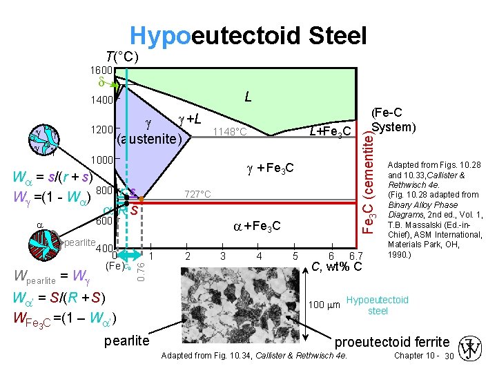
Pearlite is formed during sufficiently slow cooling in an iron-carbon system at the eutectoid point in the Fe-C phase diagram (723 °C, eutectoid temperature). In a pure Fe-C alloy it contains about 88 vol. % ferrite and 12 vol.

File:iron carbon phase diagram.svg - wikimedia commons
C Phase Diagram. ➢ α-ferrite - solid solution of C in BCC Fe. • Stable form of iron at room temperature. • Transforms to FCC g-austenite at 912 °C.67 pages

Solved by using the iron-carbon (fe-c) phase diagram | chegg.com
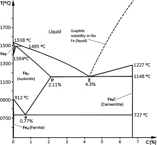
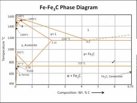
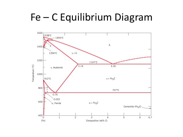
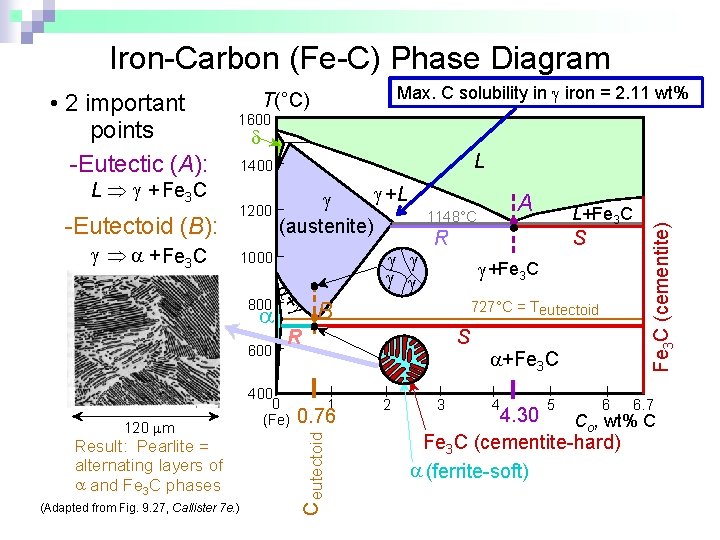
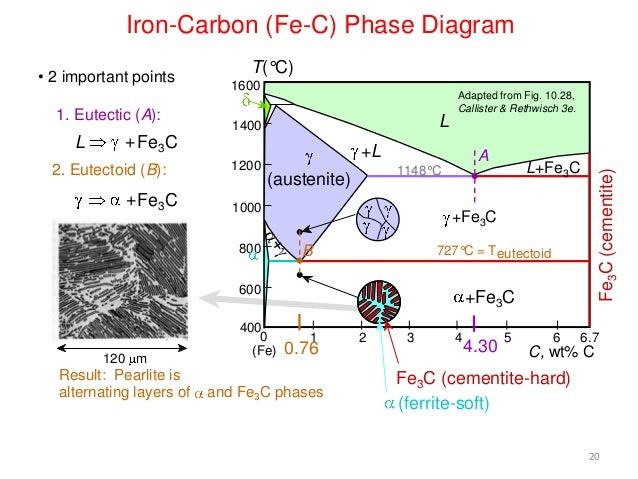
Iron-Carbon phase diagram: The Fe-Fe 3 C is defined by five individual phases and four invariant reactions. Five phases are: (i). α-ferrite: C and iron (Fe) solid solution in alpha iron (BCC). (ii). γ-austenite: C and iron (Fe) solid solution in Austenite (FCC iron).

The iron-carbon alloys and fe-c phase diagram - mechanicalbase
KEY POINTS OF Fe-C Diagram. Phases: • Liquid Fe-Tmin=1148C @ 4.3%C. • 1394 C<δ-Fe-<1538C ... When molten cast iron solidifies some of the carbon.41 pages

Pin on smithing
In Fe-C diagram there are different phases as α, δ and γ there is another phase ϵ. α and δ are BCC structure while γ is FCC. ϵ is HCP structure which exists at very high pressure. So, it does not exist on equilibrium Fe-C diagram under equilibrium conditions of temperature and pressure.

Fe-c phase diagram and microstructures | download scientific diagram
The Iron Carbon Phase Diagram · A1: The upper limit of the ferrite / cementite phase field (horizontal line going through the eutectoid point). · A2: The ...

The iron carbon phase diagram
Figure GL2.35 The Fe-C phase diagram for compositions of carbon steels below 1000 °C, including the eutectoid point. First consider cooling of pure iron, starting with FCC γ -iron at 1000 °C. At 910 °C, a solid-state change to BCC α -iron occurs and phase changes also (at constant temperature).
Fe–c system. stable and metastable equilibrium diagrams | springerlink
The Fe-C phase diagram is a fairly complex one, but we will only consider the steel part of the diagram, up to around 7% carbon. Page 2. Phases in Fe–Fe3C Phase ...7 pages
Muddiest point- phase diagrams iii: fe-fe3c phase diagram introduction
The Fe-C phase diagram is a fairly complex one, but we will only consider the Cementite Cementite or iron carbide (Fe 3C) is an intermetallic. Answer to From the Fe-Fe 3C phase diagram below, answer the following questions. (a) (8 pts) There are three transformation reactio.

Metallurgical engineering - the iron carbon phase diagram describe ...
Iron-Carbon(Fe-C) phase diagram. The iron-carbon phases and phase diagram is slightly complex, compared with other diagrams. The horizontal axis of the Fe-C ...
What is the use of an iron carbide phase diagram? - quora
The iron-iron carbide (Fe-Fe 3 C) phase diagram. Below 912 °C, pure iron exists as the alpha phase, ferrite, which has the BCC structure. Between 912 and 1,394 °C, pure iron exists as the gamma phase, austenite, which has the FCC structure. Carbon is more soluble in the FCC phase, which occupies area "γ" on the phase diagram, than it is ...

File:fe-c diagram stable.png - wikimedia commons
Eutectic point is a point where multiple phases meet. For the iron-carbon alloy diagram, the eutectic point is where the lines A1, A3 and ACM ...Mar 10, 2020 · Uploaded by MechanicsTips
![Iron-Carbon Phase Diagram Explained [with Graphs]](https://fractory.com/wp-content/uploads/2020/03/Phase-diagram-of-steel-and-cast-iron.jpg)
Iron-carbon phase diagram explained [with graphs]
Practical effects of different types of heat treatment on steel ...

Iron carbon phase diagram - google search | metal working tools ...

Solved) - looking at the iron-carbon phase diagram, below, answer ...
![Fe-C phase diagram [27] | Download Scientific Diagram](https://www.researchgate.net/profile/Peter-Barnes-7/publication/281459035/figure/fig2/AS:669087113953293@1536534207704/1-Fe-C-phase-diagram-27.png)
Fe-c phase diagram [27] | download scientific diagram
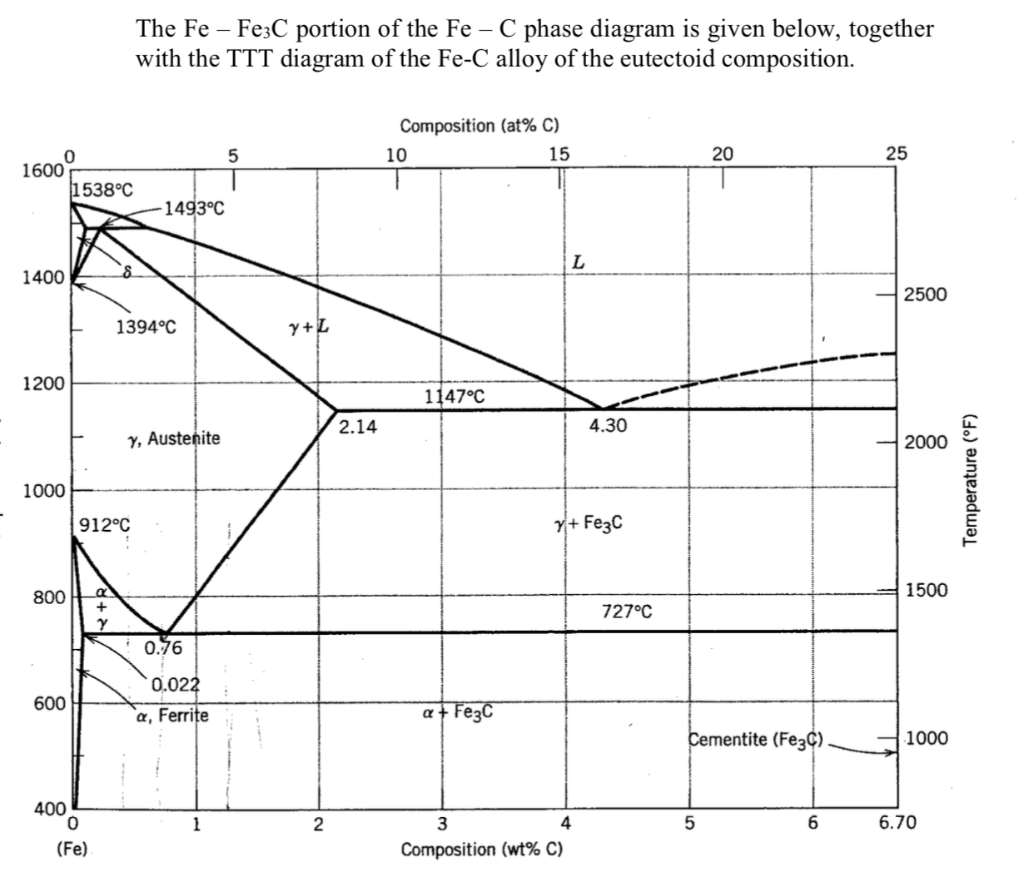
Solved the fe – fe3c portion of the fe – c phase diagram is ...

File:steel fe-c phase diagram-en.png - wikimedia commons
Chapter 10 phase diagrams issues to address when

The iron carbide (fe fe3c) phase diagram - uprm pages 1 - 50 ...

Material society: principles of heat treating of steels

Diagram fasa fe-c | pdf | heat treating | steel

Phase diagrams:
Phase equilibrium part 6 chemistry engineering department 23102013
Fe-c diagram

Applications of fe-c phase diagram .t-t-t diagram figure 5-7 ...
Practical maintenance » blog archive » the iron-iron carbide ...
![Portion of Fe-C equilibrium phase diagram.[5] | Download ...](https://www.researchgate.net/profile/Tianyu-Yu-4/publication/320531737/figure/fig5/AS:668390926585883@1536368223982/Portion-of-Fe-C-equilibrium-phase-diagram5_Q640.jpg)
Portion of fe-c equilibrium phase diagram.[5] | download ...

Iron-carbon (fe-c) phase diagram - ppt download

Gate metallurgical engineering: iron-iron carbide phase diagram

Metastable iron-carbon (fe-c) phase diagram
0 Response to "39 fe-c phase diagram"
Post a Comment