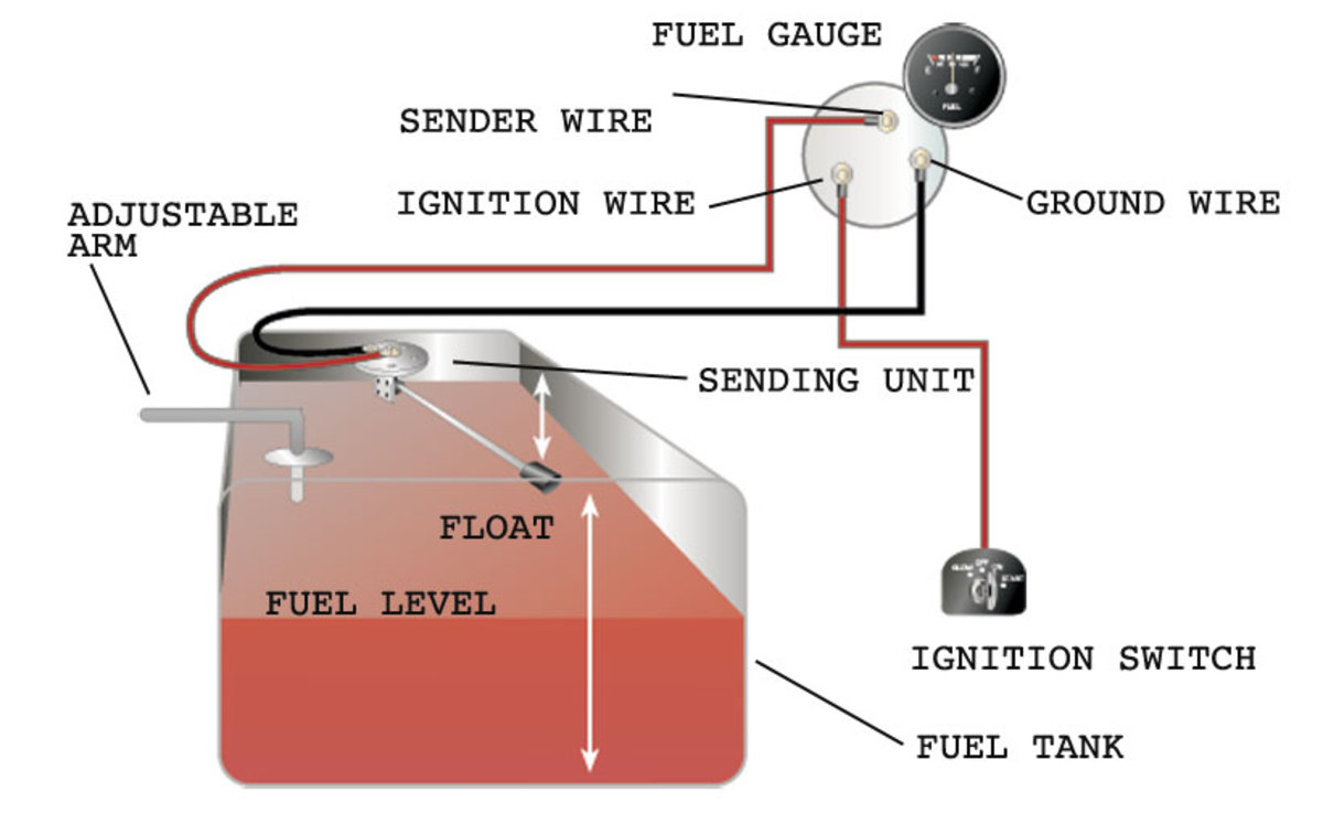
39 universal fuel gauge wiring diagram
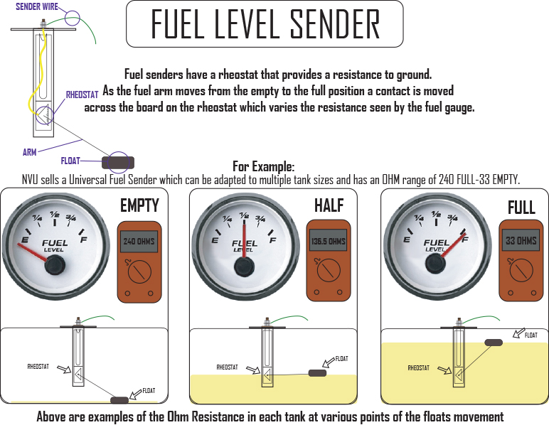
Moeller Gauge-Wiring Diagram 4″″ Universal Electric Fuel Sender Instructions Electric Fuel . Gauge pointer should be at the position shown in the lower portion of the diagram. To test senders, the resistance values are shown at minimum and full gauge scales. Fuel Systems (Marine) Voltage - "I" to "G" terminal - 10 to 16 volts. 52 results
RENAULT Car Manuals PDF & Wiring Diagrams above the page - Duster, Kajar, Kangoo, Koleos, Logan, Megane, R5, Clio, Captur, Master, Espace, Scenic, Talisman, Alaskan, Wind, Zoe, Thalia, Twizi, VelSatis, Fluence, Laguna; Renault EWDs.. In 1898, the French company Renault, specializing in the manufacture of automobiles, was founded.The brand was founded by the …
Toyota 3UZ-FE Engine | Specs, tuning, problems, etc. The fuel injection system is a sequential multiport fuel injec-tion system. Standard Parts. the ECUMaster has two Camsync inputs. Ls430 Fuse Diagram Fuse Box Diagram Lexus Ls430 Xf30 2000 2006 I. 01 IS300 wiring harness is very different than the 02+ harness at the ECU.

Universal fuel gauge wiring diagram
2 7/12/2017 - DOCU MENT NUMBER: 10-0300 ©2017A EP e rf oma ncl t i s 30-0300 X-Series UEGO Gauge Wiring Installation Diagram Gauge Connections The X-Series UEGO gauge is supplied with a Power/IO wiring harness (A) and a UEGO sensor harness (B); the harnessesare connected to the gauge as shown below.
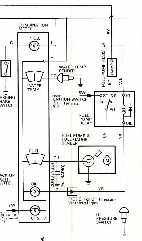
Fuel Gauge Sending Unit Wiring Diagram – wiring diagram is a simplified customary pictorial representation of an electrical circuit. It shows the components of the circuit as simplified shapes, and the skill and signal connections amid the devices.
Take control of your engine with Terminator X! Don't settle for a factory ECU with a cumbersome tuning interface when you can have complete control of your engine, self-learning fuel strategies and the proven, race-winning technology of Holley EFI at a budget-friendly price! Terminator X features real-time fuel learn, high impedance injector drivers, an integrated 1bar MAP sensor, …
Universal fuel gauge wiring diagram.
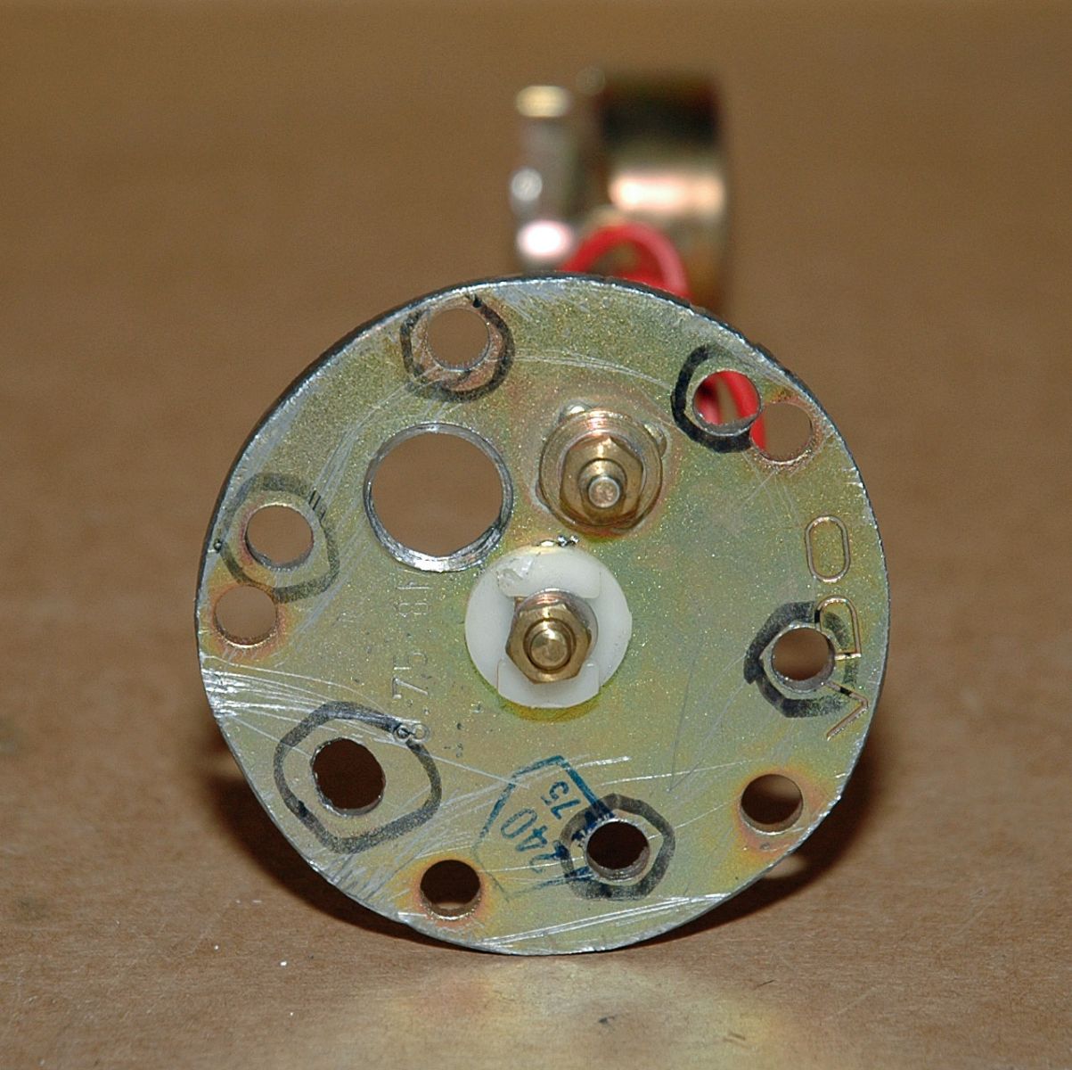
wiring instructions. Always disconnect battery ground before making any electrical connections. Parts of the Fuel Level Sender Unit to be Ad Fuel Level Sender Installation: Refer to the VDO catalog for matching fuel gauges. The unit can be adjusted to read accurately in tanks from 6" to 23" deep. Diagram B I. Measure the depth of your fuel tank.
Turbosmart product fitting Instructions provide important information regarding products, spring charts, tech drawings and graphs.
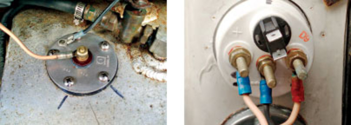
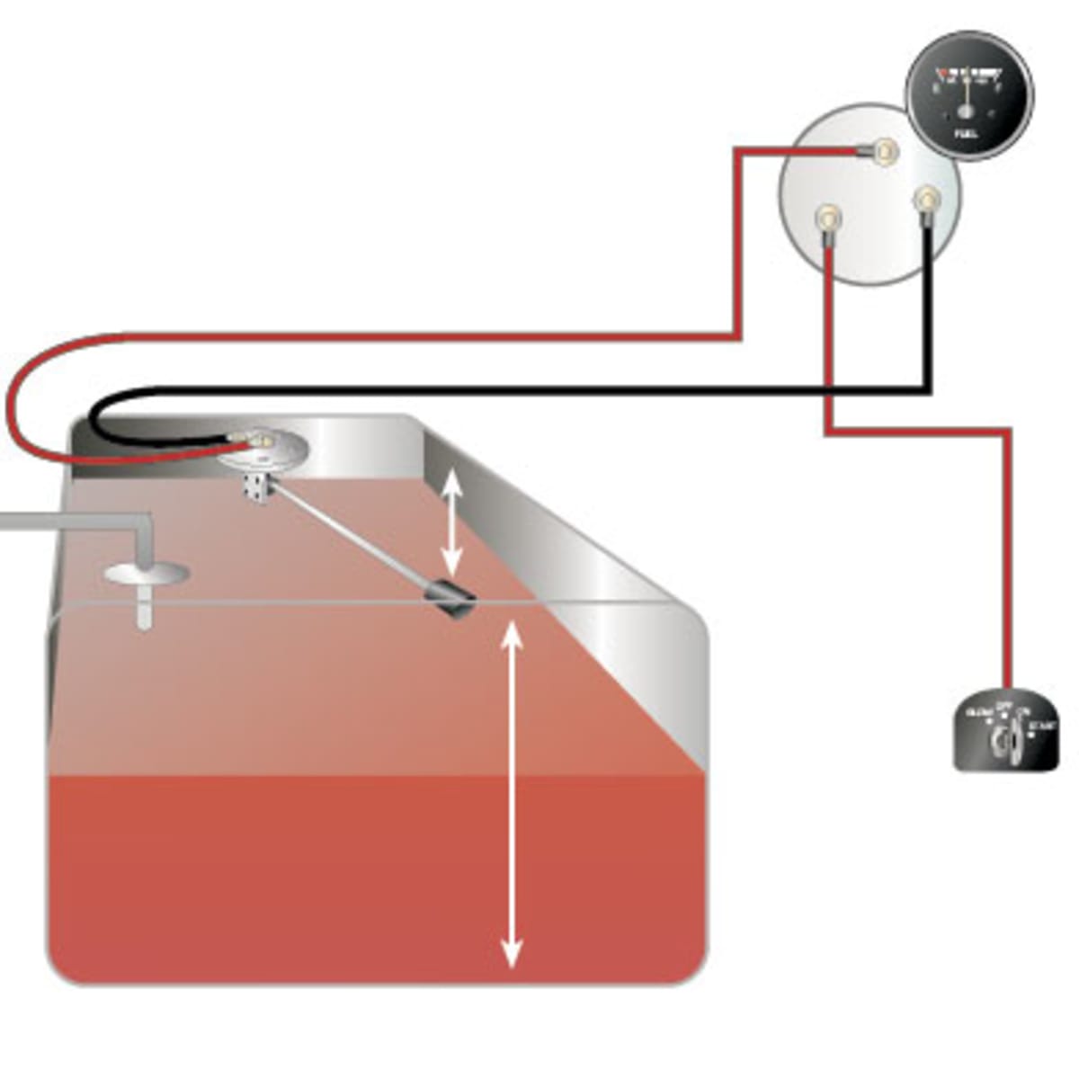
Gauge to Sender Connection 5. read the fuel level tank sender instructions and install the sender. 6.RefertoFigure 3. Route a length of 18-gauge insulated copper wire from the gauge to the sender. connect the wire to the sender. onnect the other end of the wire to the connection post on the back of the gauge marked “S”. 7.Make sure the fuel ...
17.12.2021 · Some LIFAN Motorcycle Manuals & Wiring Diagram PDF are above the page - 150, 200, 163, LF250, LF200.. History of LIFAN began in 1992, the year the company was founded on the repair, and later - and the production of motor vehicles.. Rapidly developing, after a couple of years the company mastered the production of automotive equipment, and in 1997 became the …
on gauge. White Tach sender wire Connect to the ‘SENDER’ location on gauge. (-) Black Ground Connect to each gauge (ground location) as shown in diagram. Pink 12 volt ignition feed Connect to each gauge (12 v location) as shown in diagram. Grey Instrument lamp feed Connect to instrument lamp, as shown in diagram.
From the thousands of images online with regards to fuel gauge wiring diagram, we all selects the best collections having best quality just for you, and this photos is one among images choices in this ideal images gallery in relation to Fuel Gauge Wiring Diagram.Lets hope you will like it. This specific picture (Wiring Diagram For Gas Gauge Universal Fuel Gauge Wiring Diagram inside Fuel Gauge ...
Dark Brown: Fuel sender wire. Connect to the fuel sender. Step 3: If you are using a removable gauge panel, now is a good time to determine where you are going to install each gauge and indicator light, and install them into the panel in preparation of wiring. The supplied indicator light simply presses into a 5/32” hole.
22.02.2009 · Well, here are a few more wiring diagrams for Jeep Wrangler – this time for the Jeep YJ series years 1987 to 1994. The PDF includes ‘body’ electrical diagrams and Jeep YJ electrical diagrams for specific areas like: air conditioning units, typical jeep charging unit wiring diagrams, typical emission maintenance reminder wiring diagrams, front end lighting wiring …
Boat Fuel Tank Gauge Wiring Diagram – wiring diagram is a simplified standard pictorial representation of an electrical circuit. It shows the components of the circuit as simplified shapes, and the power and signal links surrounded by the devices.
11681_universal kill switch & lanyard 11701_horn switch 11751_push button switch ... 15501_fuel gauge kit 15521-15577_reed switch 15xxx_seachoice series gauges ... 72103_in-dash digital receiver wiring diagram 72103_in-dash marine gauge digital receiver 85800_type v inflatable 85810_type v inflatable
As stated earlier, the traces at a Universal Fuel Gauge Wiring Diagram signifies wires. Sometimes, the wires will cross. But, it doesn’t mean connection between the cables. Injunction of 2 wires is generally indicated by black dot on the intersection of two lines. There will be main lines that are represented by L1, L2, L3, and so on.
From the thousands of photographs on the internet with regards to equus fuel gauge wiring diagram, we selects the very best choices having ideal quality simply for you all, and now this photos is considered one of pictures collections in this best pictures gallery in relation to Equus Fuel Gauge Wiring Diagram.I really hope you’ll like it. This graphic (Gas Gauge Wiring Diagram Universal ...
12.07.2017 · boat 12v switch panel wiring diagram; boat fuel sending unit wiring diagram; boat stereo wiring diagram; boat switch panel wiring diagram; boat trailer wiring diagram 4 wire; boat voltage gauge wiring diagram; bobcat skid steer wiring diagram; bosch relay headlight wiring diagram; bosch universal oxygen sensor wiring diagram; boss snow plow ...
21.11.2018 · In this case, you will need a set of wiring taps and a pair of pliers. Trailer Wiring Diagram. To connect the electric system of your trailer to the vehicle, you will be using special connector. Above we have describes the main types of trailer wiring diagrams. Below is the generic schematic of how the wiring goes. 4 pin trailer wiring diagram

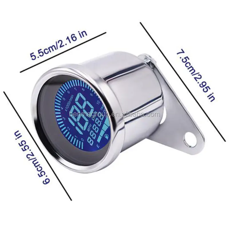
Samdo universal fuel gauge digital fuel level gauge marine fuel meter full waterproof signal adjustable 7 color backlight 52mm 12v/24v 0-190ohm, ...

Wonvon fuel level gauge,2" 52mm universal car motorcycle fuel level meter gauge 12v led light display fuel tank gauge boat truck rv
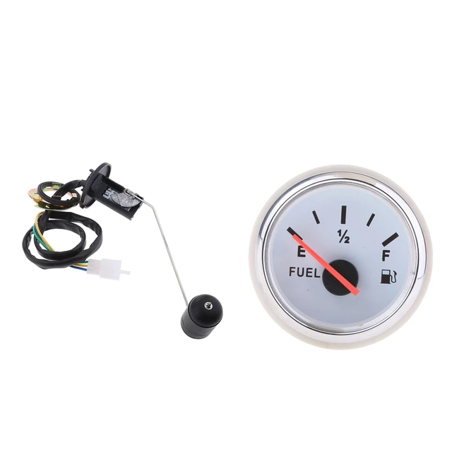
Universal 2' 12v car fuel level gauge meter e-1/2-f pointer + fuel sensor jauge de carburant indicador de nivel de combustible














0 Response to "39 universal fuel gauge wiring diagram"
Post a Comment