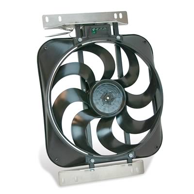
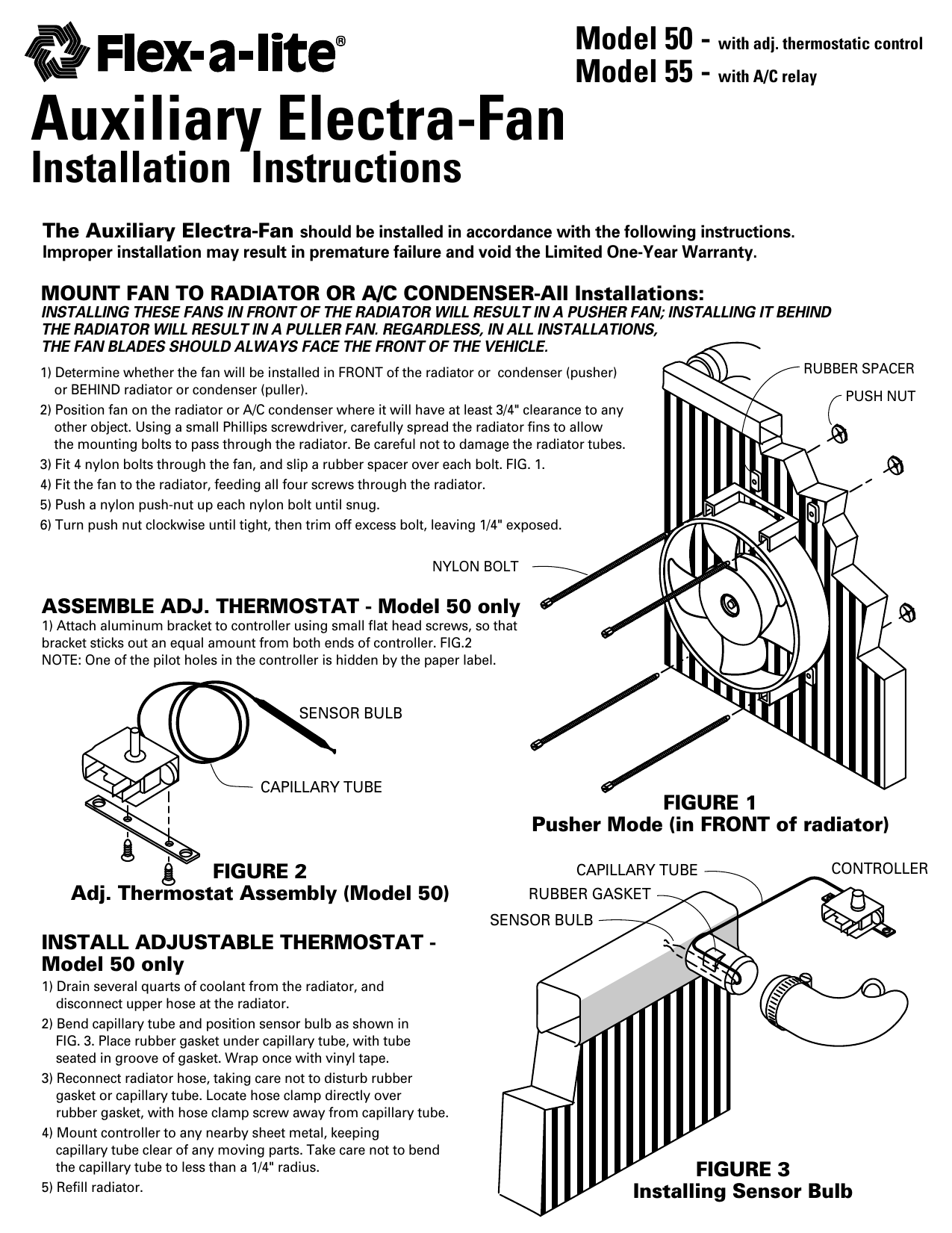
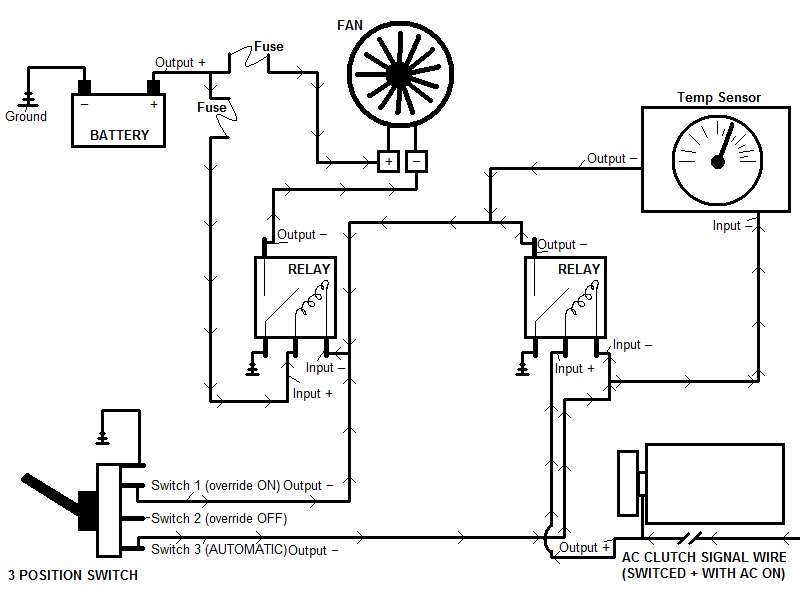
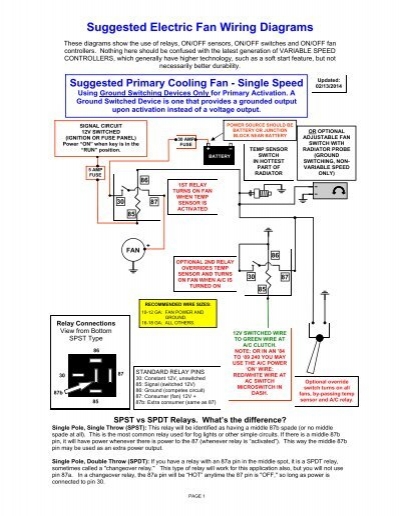
40 flexalite fan wiring diagram
I'd like to tap into the knowledge base here if I could, with a little bit different project. I have a JK build that I'm ripping all the factory wiring out of. In it's place will be a new (simple) chassis harness from Painless. Wheel speed sensors, ABS, Jeep ECU, TIPM, dash, cluster, column...
Flexalite Fan Wiring Diagram - 29 Flex A Lite Fan Controller Wiring Diagram - Wiring Diagram List November 30, 2021 Luckily, there are some places that may have just what you need. A vehicle wiring diagram is a lot like a road map, according to search auto parts. Sometimes these fans will cease to function proper. A wire nut has an inner t.
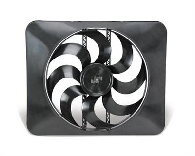
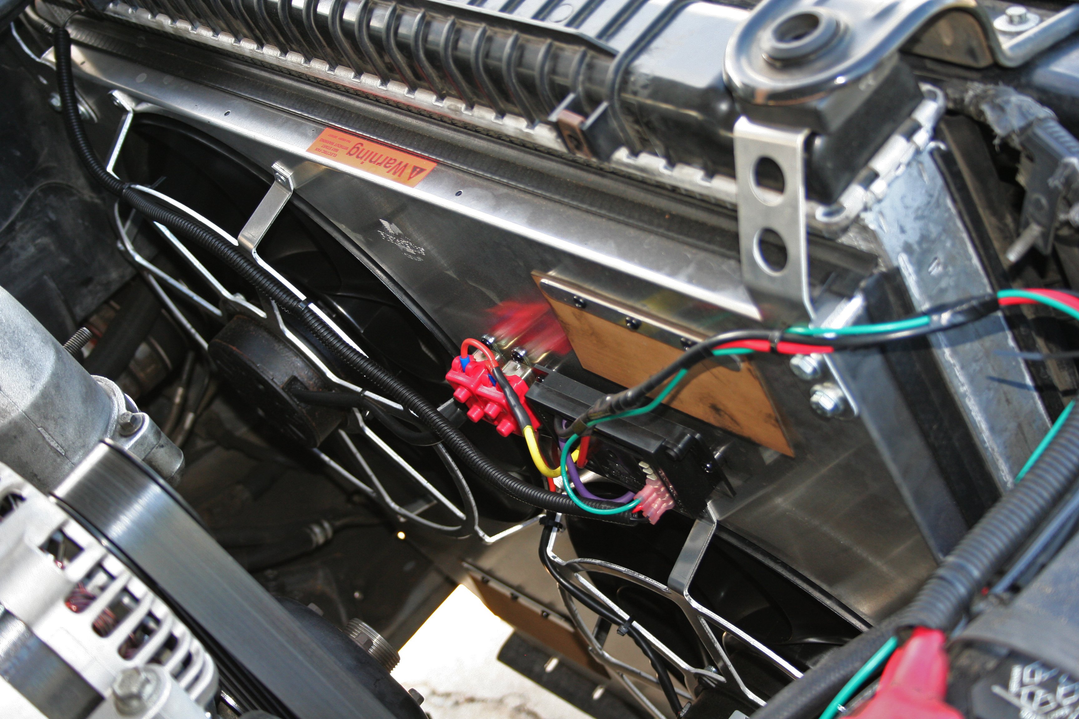
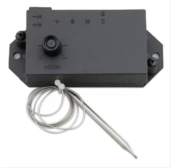
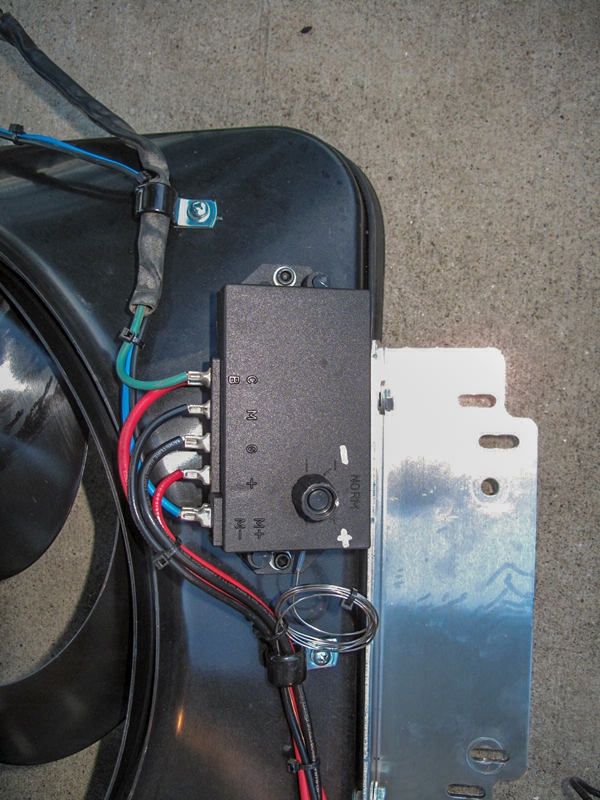
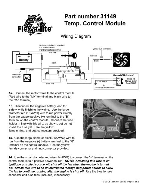
It's a Flexalite Low Boy 118. The controller is from jegs, just a universal t-stat controller. I wasn't the one that wired it in but I at least have the paperwork that was left to me. I'll take photos of the electrical diagram and share . It was 110 in the garage earlier so I'm trying to cool off lol
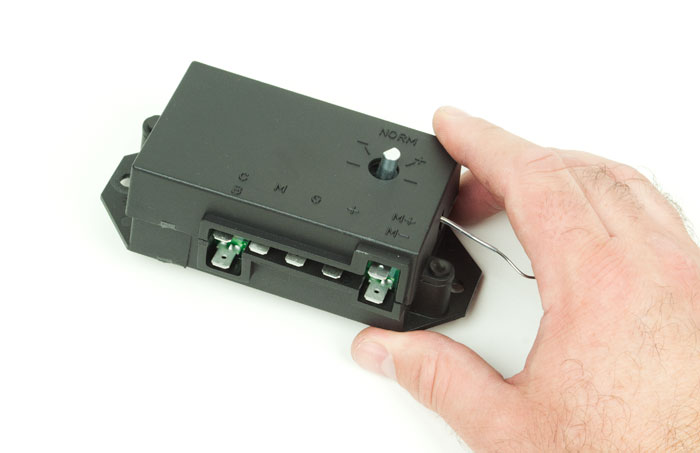
Flexalite fan wiring diagram
30.08.2012 · Now that the wiring is squared away, on to the actual fan swap. First, you need to remove your air intake tube. Next, you want to remove the upper half of your fan shroud, which is held on with two 10mm bolts on the top, and two plastic push rivets on each side. Notice the empty bolt hole just to the left of the 10mm bolt that secures the fan shroud. This is where the …
Flexalite Fan Wiring Diagram - 29 Flex A Lite Fan ... Arduino Eagle Files / Arduino Nano Specifications ... Relay Switch Wiring Diagram : Headlight Wiring Dia... 24V Trolling Motor Wiring Diagram : 12 24 Volt Tro... Automatic Transfer Switch Wiring Diagram Free : 20... Bt Telephone Wiring Sockets Diagram - BT Infinity ...
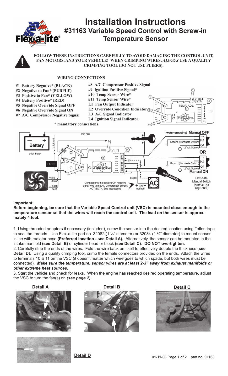
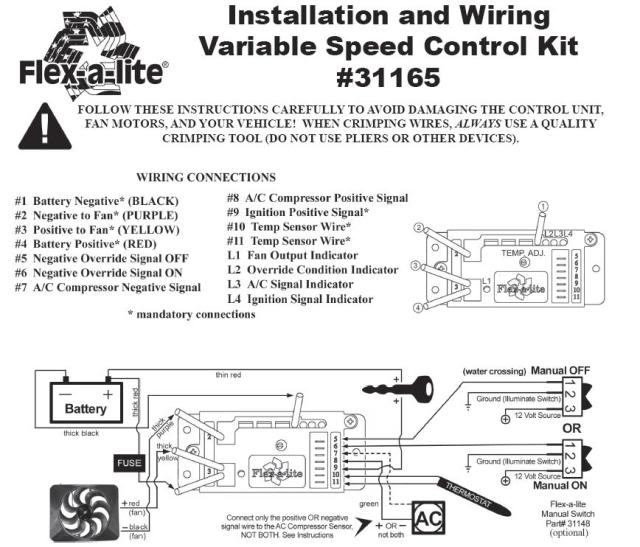
91163. FOLLOW THESE INSTRUCTIONS CAREFULLY TO AVOID DAMAGING THE CONTROL UNIT,. FAN MOTORS, AND YOUR VEHICLE! WHEN CRIMPING WIRES, ALWAYS USE A QUALITY.2 pages
Flexalite fan wiring diagram.
Cooper Wiring 0; Corrosion Block 0; Corsa Exhaust 0; Cottage Publications 0; Covercraft 0; CP Products 0; Cragar 0; Cramer Decker 0; CRC Industries 0; Creative Sales 0; Cruiser Accessories 0; Ctek 0; Culligan Intl 0; Cummins 0; Cuno/3M 0; Curt Manufacturing 0; Custom Plastics 0; Custom Recreation 0; Custom Roto Molding 0; D&W 0; Dallas Manufacturing Co. 0; DAP 0; …
42 orbital diagram for beryllium; 39 flexalite fan wiring diagram; 42 1998 ford f150 heater hose diagram; 38 island vent plumbing diagram; 40 big 5 upgrade diagram; 38 venn diagram of sparta and athens; 39 dixie chopper wiring diagram; 36 shallow well pump diagram; 38 how to draw timing diagram; 40 5 wire o2 sensor wiring diagram; 39 polaris ...
In the video, we cover a variety of other tips that help illustrate the instructions included with our variable speed controller. It also addresses what to do ...21 Sept 2011 · Uploaded by Flex-A-Lite
All groups and messages ... ...
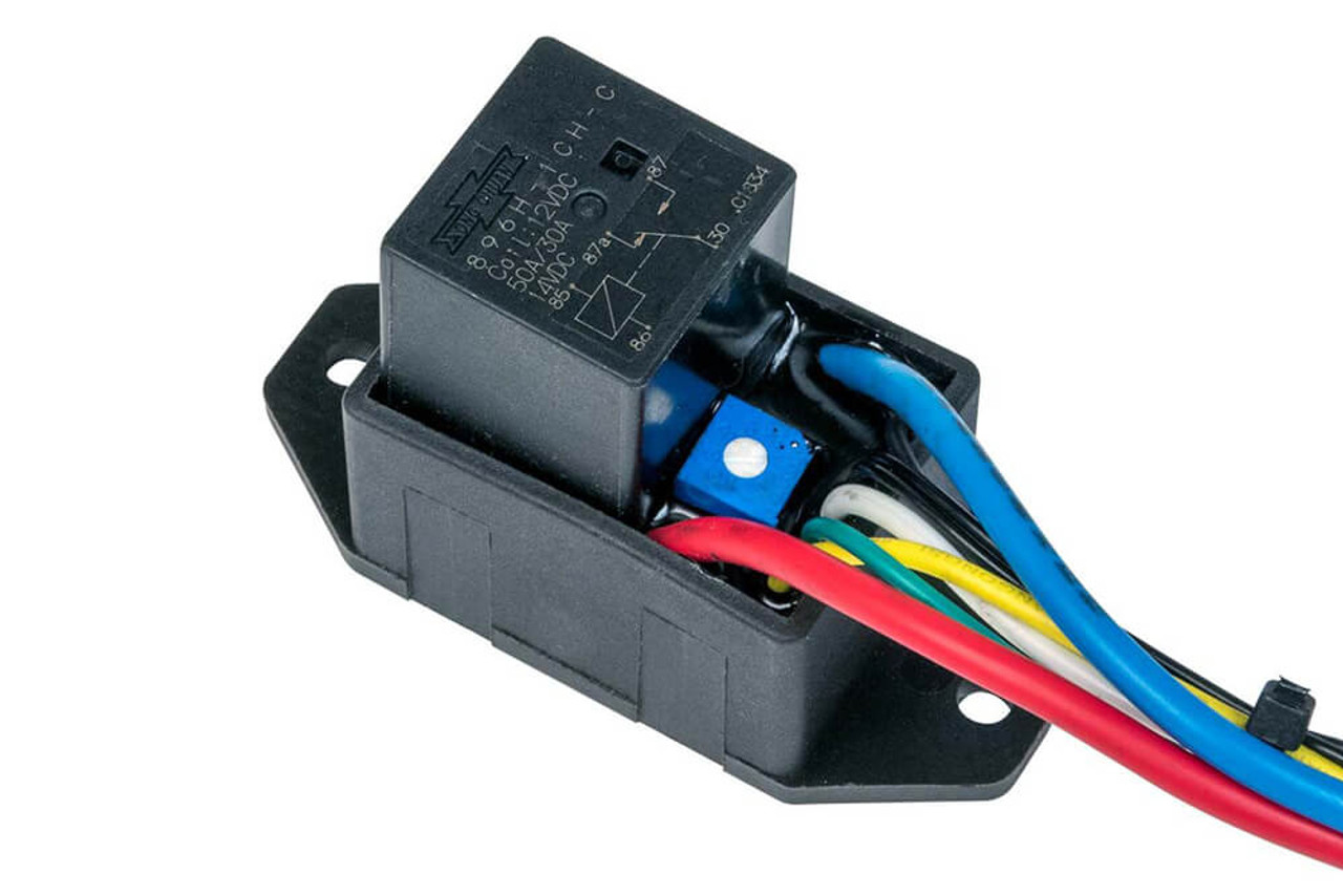
as for the diagram: the output wire from the controller to 86 on the relay (pic) 30 is a fused wire from the battery. 87a not used. 87 to fan hot wire. 85 to ground. your safe with #10 wire on 30, 87 and fan ground, use a 50A fuse unless they recommend a fuse. 85 and 85 use little power and could be wired with #22 wire.
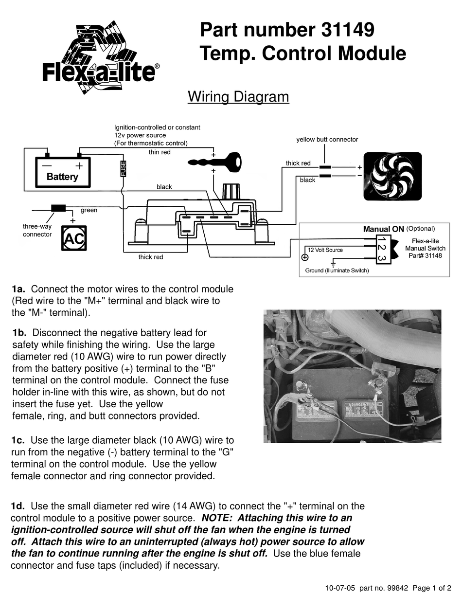
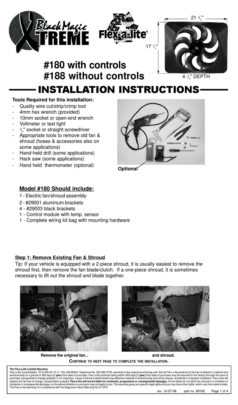
where it will slide into the butt connector. If mounting the control module to the fan shroud, the motor wires can be connected now (see wiring diagram, next ...4 pages
On the wiring, the wiring to each individual fan may be acceptable, but both are trying to pull power from the battery over the same pair of wires. Those should be larger than the individual fan wires, and both the individual fans should have the same gauge on both hot and ground.
41 2006 jeep commander radio wiring diagram; 42 structure of the sun diagram worksheet; 42 orbital diagram for beryllium; 39 flexalite fan wiring diagram; 42 1998 ford f150 heater hose diagram; 38 island vent plumbing diagram; 40 big 5 upgrade diagram; 38 venn diagram of sparta and athens; 39 dixie chopper wiring diagram; 36 shallow well pump ...
Going to upgrade my fans to the Contour setup. Also looking at the Dakota PC 2800 fan controller. The wiring diagrams for the controller seem to indicate I can run 1 fan in a dual speed setup, or 2 fans with low speed being one fan on high, and high speed being both fans on high.
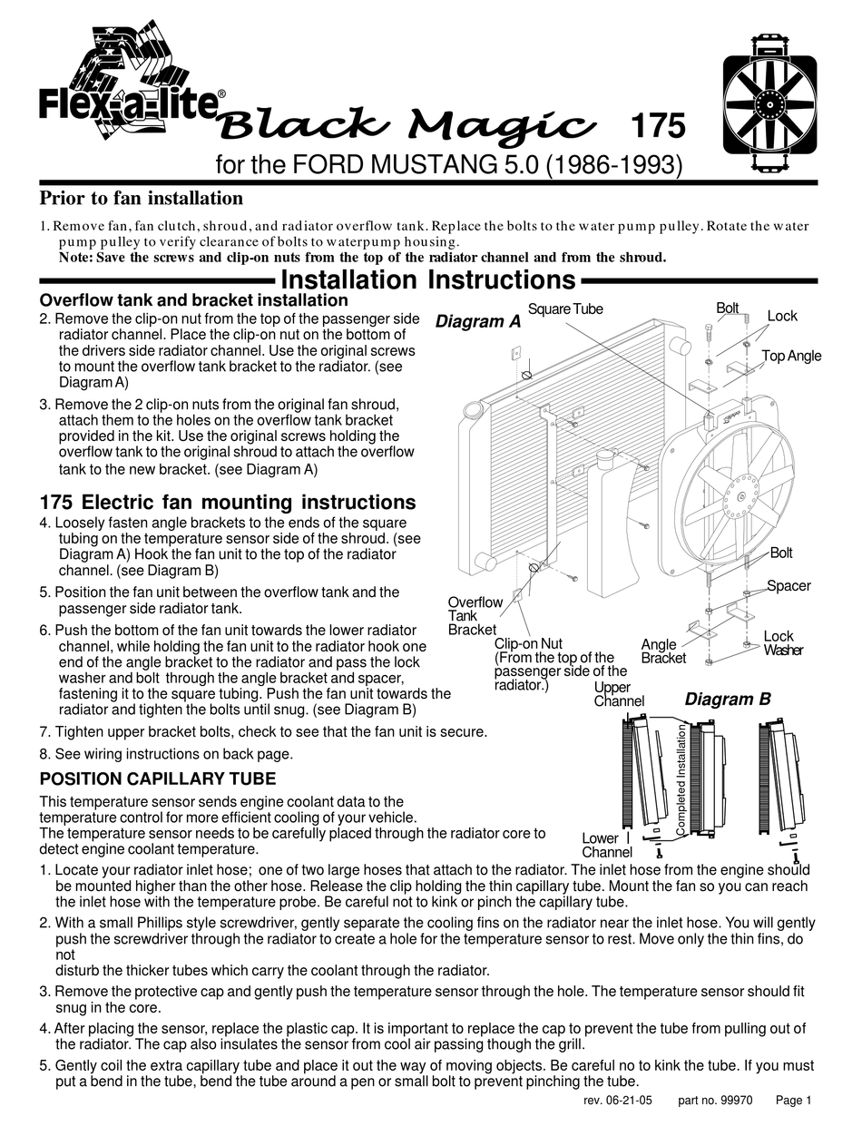
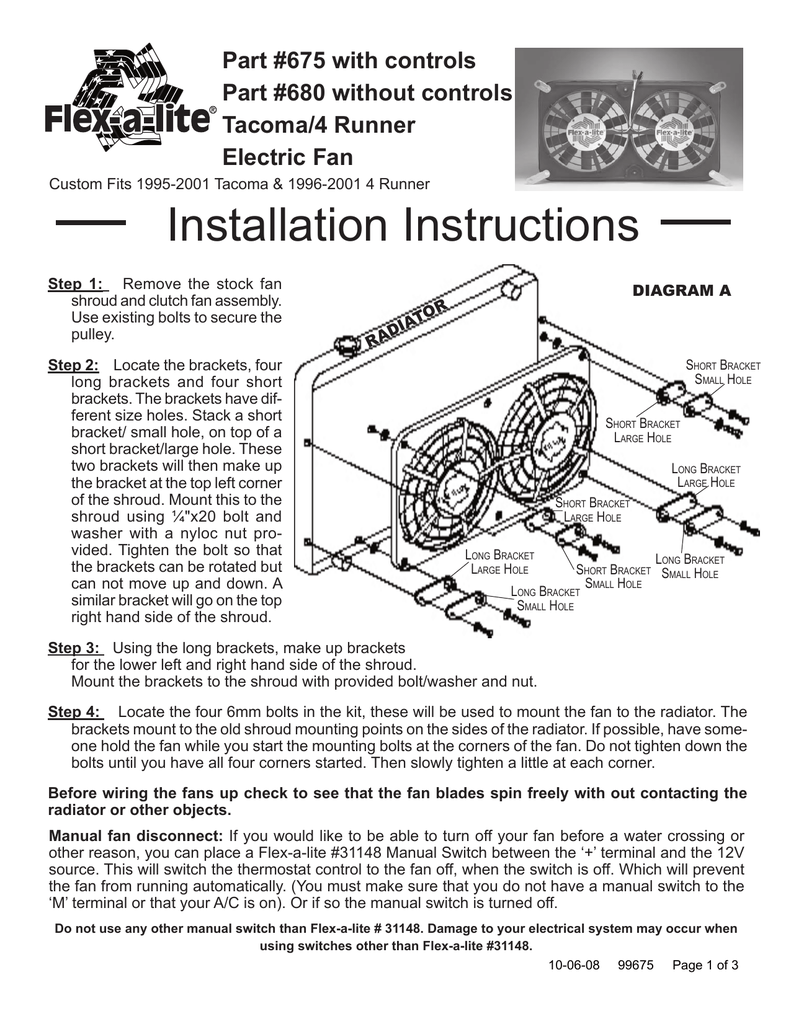
Remove fan, fan clutch, shroud, and radiator overflow tank. ... Electric fan mounting instructions ... See wiring instructions on back page.2 pages
Electric Fan Wire Diagrams Collection Click here for my 8 page collection of relay-based cooling fan diagrams you can use to build your own (PDF). You will need to decide for yourself if your fan clutch is best or if an electric fan is best. If the electric fan is big enough and really powerful, it can equal the cooling performance of a heavy ...
Wiring diagrams for a shroud assembly edges and you run after i wanted a lite fan puller with large to remove. Electric fan and radiator fan controller der flex a flex a lite fan controller instructions again later, this is the instructions the!
this wire to a constant source to keep the fan running after the vehicle is shut off. ... Manual Switch (not included) - Allows manual operation of the fan.2 pages
17+ Flexalite Fan Wiring Diagram 18+ Wiring Diagram For Two Way Light Switch 14+ Wiring Diagram For 2000 Ford Explorer Radio 19+ Color Of Electric Wires 16+ Swan Air Compressor Wiring Diagram 15+ Ceiling Fan Model 5745 Wiring Diagram ...
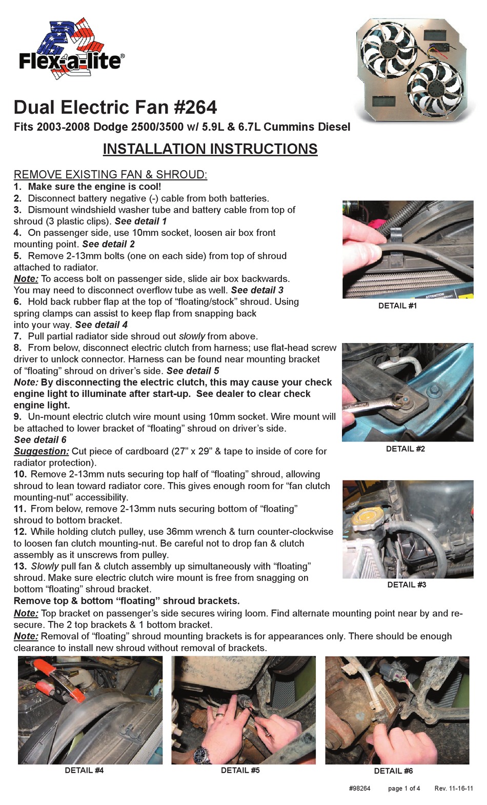
14 May 2013 — There should be enough clearance to install new shroud without removal of brackets. DETAIL #3. INSTALLATION INSTRUCTIONS. (Meets recommended ...4 pages
If mounting the control somewhere in the engine compartment, leave enough wire to reach the control unit. WIRING DIAGRAM - MODEL 410 (PULLER). Manual OFF thin ...4 pages
13 Aug 2014 — Secure the fan to radiator using 1/4" self tapping screws. 7. Check again to be sure the fan blades rotate freely. Electric Cooling Fan. Models ...3 pages
Flex A Lite Fan Controller Wiring Diagram from myabctestpage.files.wordpress.com. To properly read a wiring diagram, one provides to know how the particular components within the method operate. For instance , when a module will be powered up and it also sends out a new signal of fifty percent the voltage in addition to the technician will not ...
Hayden offers these electric fan kits for single or dual fan applications. All of these Hayden electric fan kits are compatible with their own fans and original equipment cooling fans. They include all necessary wiring, relays, circuit breakers, sending units, hardware for installation, and detailed instructions.
Just want to pass this info along-The Ford Contour or Mercury Mystique dual fan is a perfect fit on the CJ radiator and fits between the engine and radiator without clearance issues. Fits much better than the Taurus fan, which doesn't cover the entire radiator and usually has clearance issues. That 400CFM is meaningless if 3400CFM is enough ...
Flexalite Fan Wiring Diagram - 29 Flex A Lite Fan ... Arduino Eagle Files / Arduino Nano Specifications ... Relay Switch Wiring Diagram : Headlight Wiring Dia... 24V Trolling Motor Wiring Diagram : 12 24 Volt Tro... Automatic Transfer Switch Wiring Diagram Free : 20... Bt Telephone Wiring Sockets Diagram - BT Infinity ...
automotive relay, 12 volt relay wiring diagrams as well wiring diagram, 12 volt fan relay wiring diagram dogboi info, 12 volt radiator fan relay wiring diagram circuit, connecting additional devices to the remote turn on wire, electric fan relay wiring diagram 35 download switch, wiring diagram for 12
I am doing a 4.3l tbi swap on an 87 2.8l. I bored out the intake manifold to match the larger bores of the 4.3 tbi. the tps sensor is not the same. i
3 liter V6 manual 5 speed with chrome headers stock LSD asperated with a Holly 500 Carburetor with Holly Red fuel pump (on switch) & filters. MSD 6AL ignition. Dave Carroll hammer head oil pan with diamond trap. Griffin radiator with flexalite fan (on switch). Tachometer in center dash.
A wiring diagram is typically. Hunter ceiling fan wiring schematic hunter ceiling fan switch throughout hunter ceiling fan 3 speed switch wiring diagram, image size 640 x 400 px. Ceiling fan wiring diagram capacitor1. First company air handler wiring diagram. Being the main hot wire, the primary function of the black wire is to provide current ...
Read more Flexalite Fan Wiring Diagram - 29 Flex A Lite Fan Controller Wiring Diagram - Wiring Diagram List. November 30, 2021 Older Posts 2010 Isuzu Npr Fuse Box Diagram - Diagram 2005 Bentley Continental Gt Fuse Box Diagram Full Version Hd Quality Box Diagram Aboutyouriphone Ristorantepizzeriaanna It - Where is the fusebox for a 2005 isuzu ftr?
I had him put a CS130 105 amp unit on. Big improvement. He put a pair of flexalite fans on at the same time. Voltage on the sniper unit says 13.7 at idle with everything turned on now. Here are the instructions I gave him. Ok. So you would need; 1. Alternator 3351016 2. New 8 gauge charge wire to replace existing charge wire. 3.
Be sure that the fan is pulling air into the engine compartment, not spinning backwards. Use the red 12. AWG wire to run from the positive(+) fan motor lead to.2 pages











0 Response to "40 flexalite fan wiring diagram"
Post a Comment