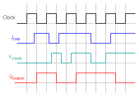
40 negative edge triggered jk flip flop timing diagram
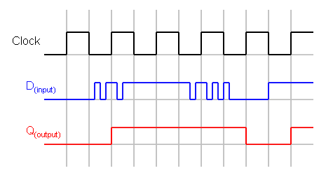
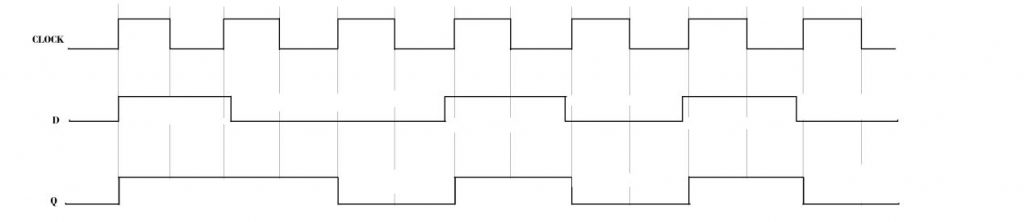
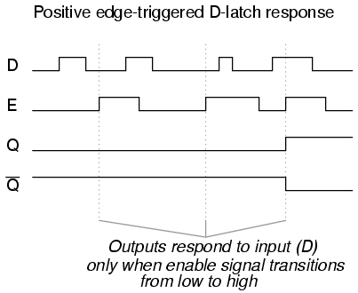
The timing diagram for the negatively triggered JK flip-flop: Latches. Latches are similar to flip-flops, but instead of being edge triggered, they are level triggered.. The most common type of latch is the D latch.While CK is high, Q will take whatever value D is at. When CK is low, Q will latch onto the last value it had before CK went low, and hold it until CK goes high again.
Slide 3 of 7
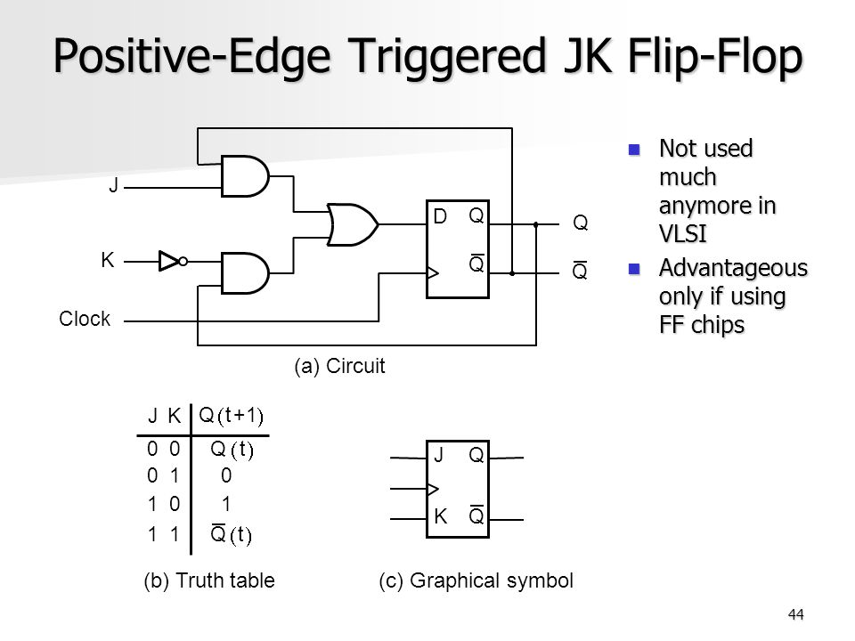
The circuit diagram of the JK Flip Flop is shown in the figure below:. The S and R inputs of the RS bistable have been replaced by the two inputs called the J and K input respectively. Here J = S and K = R. The two-input AND gates of the RS flip-flop is replaced by the two 3 inputs NAND gates with the third input of each gate connected to the outputs at Q and Ǭ.

Negative edge triggered jk flip flop timing diagram
• Edge-triggered: Read input only on edge of clock cycle (positive or negative) • Example below: Positive Edge-Triggered D Flip-Flop • On the positive edge (while the clock is going from 0 to 1), the input D is read, and almost immediately propagated to the output Q. Only the value of D at the positive edge matters. D C S C R D Clock Q Q
via YouTube Capture
This circuit also makes use of the asynchronous SET and RESET inputs of the D Type flip-flop, and because the D Type is edge triggered, this version of a JK flip flop is truly edge (not level) triggered. It is also possible to use a negative edge triggered D Type flip-flop to make a negative edge triggered JK flip-flop by this method.
Negative edge triggered jk flip flop timing diagram.
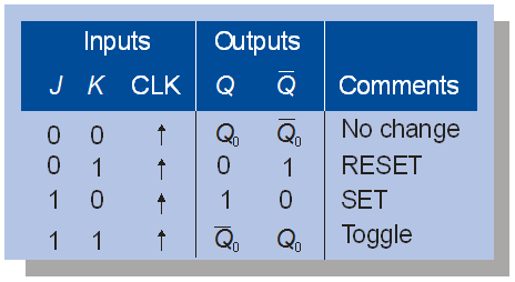
I'll consider the following JK-flip flop truth table. Let's analyze it for each clock edge. CLK edge 1: The output was initially zero (or to be precise, high impedance) and at edge1, INPUT = J = 0. So, the output should be zero in this clock cycle. CLK edge 2: The output in the previous cycle was zero and INPUT= 0 at edge2. Again, the output in ...
Timing diagram - Let us assume that the clock is negative edge triggered so above counter will act as an up counter because the clock is negative edge triggered and output is taken from Q. Counters are used very frequently to divide clock frequencies and their uses mainly involve in digital clocks and in multiplexing.
While this implementation of the J-K flip-flop with four NAND gates works in principle, there are problems that arise with the timing. The timing pulse must be very short because a change in Q before the clock pulse goes off can drive the circuit into an oscillation called "racing".Modern ICs are so fast that this simple version of the J-K flip-flop is not practical (we put one together in the ...
JK flip-flop is a sequential bi-state single-bit memory device named after its as ( Table II) timing diagram for positive edge-triggered jk flip flop.Typical applications for SR Flip-flops. The basic building bock that makes computer memories possible, and is also used in many sequential logic circuits is the flip-flop or bi-stable circuit.
The circuit diagram of the J-K Flip-flop is shown in fig.2 . Fig.2. The old two-input AND gates of the S-R flip-flop have been replaced with 3-input AND gates .And the third input of each gate receives feedback from the Q and Q' outputs. Now from the above diagram it is clear that, this allows the J input to have effect only when the circuit ...
Aug 7, 2017 — Inside the flip flop, you have a High Pass filter ( CR circuit) and diode combination that converts the clock pulse to the edges. Here only the negative edge is ...4 answers · 4 votes: Works exactly the same as a positive edge triggered JK flop. In fact, you can use the ...Why is it necessary to edge trigger JK flip flop? - Quora3 answersAug 2, 2018Design MOD-10 asynchronous UP counter using ...1 answerApr 2, 2020More results from www.quora.com
Prerequisite - Flip-flop types and their Conversion Race Around Condition In JK Flip-flop - For J-K flip-flop, if J=K=1, and if clk=1 for a long period of time, then Q output will toggle as long as CLK is high, which makes the output of the flip-flop unstable or uncertain. This problem is called race around condition in J-K flip-flop. This problem (Race Around Condition) can be avoided by ...
3-bit Ripple counter using JK flip-flop - Truth Table/Timing Diagram. In the 3-bit ripple counter, three flip-flops are used in the circuit. As here 'n' value is three, the counter can count up to 2 3 = 8 values .i.e. 000,001,010,011,100,101,110,111. The circuit diagram and timing diagram are given below. Binary Ripple Counter Using JK ...
Negative edge-triggered (with bubble at Clock input): S-R, J-K, and D. The S-R, J-K and D inputs are called synchronous inputs because data on these inputs are ...
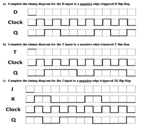
A negative edge triggered D flip-flop has a single input D which is presented at the output Q at the negative edge of the clock pulse. When is 0 the output of the flip-flop is set and when is 0, the output of the flip-flop is 0.. Write the truth table for negative edge-triggered D flip-flop.
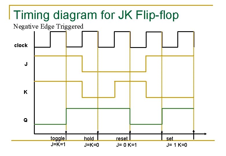
Positive atau Negative edge triagered berarti pen-trigger-an hanya dilakukan pada tepi positif-nya (rising edge) saja atau tepi negatif-nya (falling edge), bukan pada seluruh Pulsa Clock. Timing Diagram Dari Positive Edge Triggered JK Flip-flop diberikan pada gambar 4.
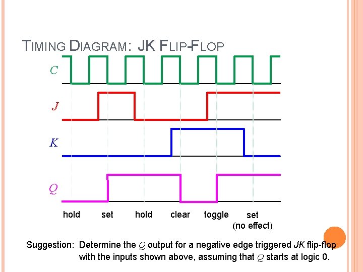
T Flip-Flop (Timing Diagram) [ Figure 5.15d from the textbook ] 1 1 0 0 11 1 0 1 1 0 1 T Flip-Flop (Timing Diagram) [ Figure 5.15d from the textbook ] 1 1 0 0 11 1 0 1 1 0 1 ... a Negative-Edge-Triggered JK Flip -Flop Q Q Clock J K . Questions? THE END. Title: 26_T_and_JK_Flip-Flops Author: Alexander Stoytchev
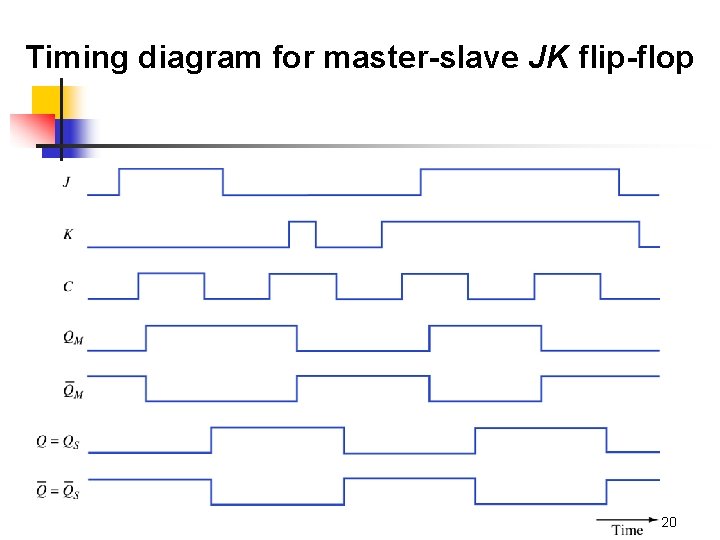
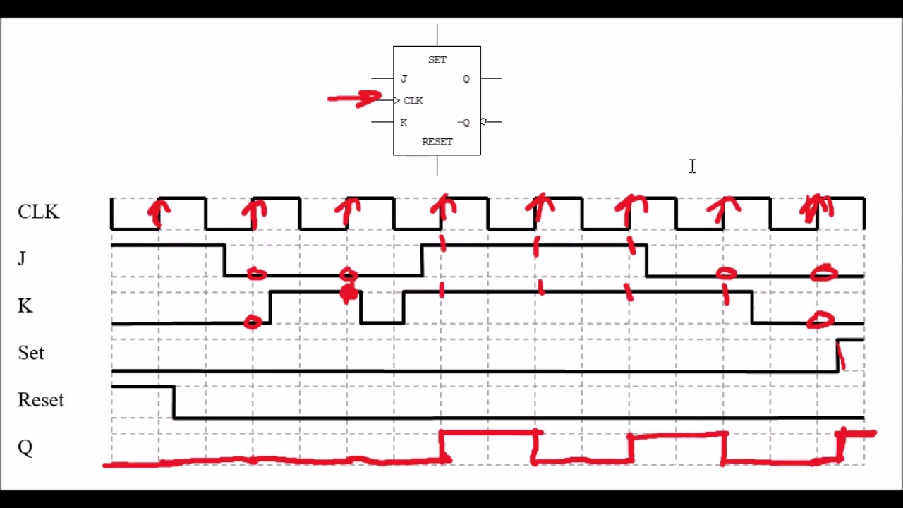
Sec 10 06 to 07 master--slave and edge-triggered j-k flip-flop
The J-K flip-flop block has three inputs, J, K, and CLK. On the negative (falling) edge of the clock signal (CLK), the J-K Flip-Flop block outputs Q and its ...

Solved) - determine the q output for a negative-edge-triggered j-k ...
The below diagram shows the 3-bit asynchronous down counter. Since it is a 3-bit counter, 3 negative edge-triggered flip-flops are used. The clock pulse input is given only to the first flip-flop. The clock input of the remaining flip-flops is triggered by the Q output of the previous flip-flop.
Flip-flops and latches - northwestern mechatronics wiki
This is known as positive edge-triggering. There is such a thing as negative edge triggering as well, and it produces the following response to the same input signals: Whenever we enable a multivibrator circuit on the transitional edge of a square-wave enable signal, we call it a flip-flop instead of a latch.
Flipflops basic concepts flipflops n a flipflop is
Description. The J-K Flip-Flop block models a negative-edge-triggered J-K flip-flop. The J-K flip-flop block has three inputs, J, K, and CLK.On the negative (falling) edge of the clock signal (CLK), the J-K Flip-Flop block outputs Q and its complement, !Q, according to the following truth table.In this truth table, Q n-1 is the output at the previous time step.
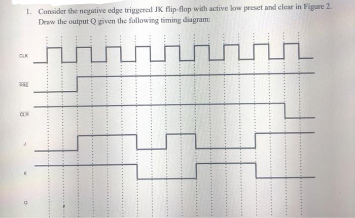
Answered: 1. consider the negative edge triggered… | bartleby
JK Flip Flop-. JK flip flop is a refined & improved version of SR Flip Flop. that has been introduced to solve the problem of indeterminate state. that occurs in SR flip flop when both the inputs are 1. In JK flip flop, Input J behaves like input S of SR flip flop which was meant to set the flip flop. Input K behaves like input R of SR flip ...
Sequential logic and flip flops sequential logic circuits
Fundamentals of Logic Design (6th Edition) Edit edition Solutions for Chapter 11 Problem 22P: Fill in the timing diagram for a falling-edge-triggered J-K flip-flop. (a) Assume Q begins at 0. (b) Assume Q begins at 1, but Clock, J, and K are the same. ….
Flip-flops and latches - northwestern mechatronics wiki
Electronics Tutorial about JK Flip Flop and Master-Slave JK Flip Flop used ... the “Slave” circuit, which triggers on the falling edge of the clock pulse.

Master-slave jk flip flop - geeksforgeeks
Moreover it is to be noted that the working of the negative edge-triggered flip-flop is similar to that of positive-edge triggered one except that the changes occur at the trailing edge of the clock pulse instead of its leading edge. JK Flip Flop Timing Diagram

Timing diagram for a negative edge triggered flip flop
In negative edge triggered flip flops the clock samples the input lines at the negative edge (falling edge or trailing edge) of the clock pulse. The output of the flip flop is set or reset at the negative edge of the clock pulse. A symbolic representation of negative edge triggering has been shown in Figure 3.

Jk flip-flop - power electronic
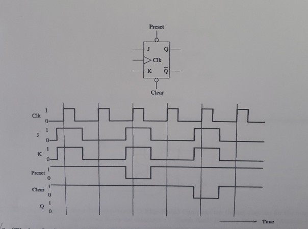
Timing Diagram. The 'Edge triggered D type flip-flop with asynchronous preset and clear capability', although developed from the basic SR flip-flop becomes a very versatile flip-flop with many uses. A timing diagram illustrating the action of a positive edge triggered device is shown in Fig. 5.3.5.
Flip flops department of it sarita nahak lect
The D flip-flop, which changes its output according to the input with the -ve. transition of the clock pulse of the flip-flop, is a -ve. edge triggered flip-flop. The negative edge D flip-flop can be represented with a triangle and a bubble at the clock end of the D flip-flop block diagram. Negative Edge Triggered D flip flop Circuit Diagram
Jk flip flop timing diagrams
The output of the flip flop changes at high or low input, i.e., level triggered. Master-slave JK flip flop can be used in both triggered ways; in edge-triggered, it can be +ve edge-triggered or -ve edge triggered. In edge-triggered, the master flip flop is derived from the +ve edge of the clock pulse. At that time, the slave flip flop is in the ...
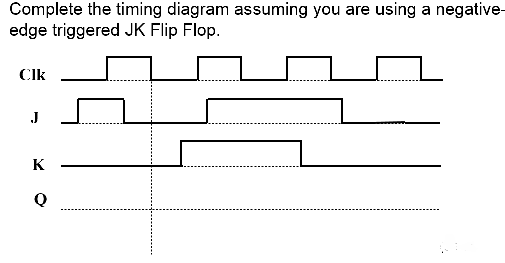
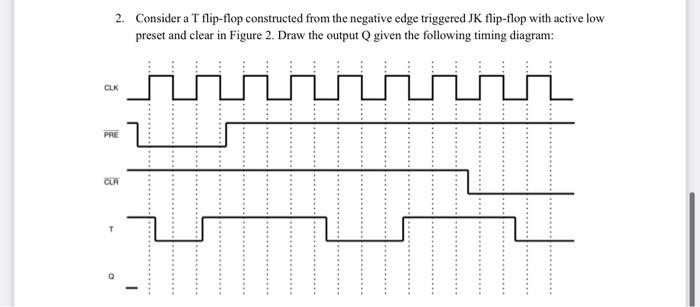
Solved complete the timing diagram assuming you are using a ...
The J (Jack) and K (Kilby) are the input states for the JK flip-flop. The Q and Q' represents the output states of the flip-flop. According to the table, based on the inputs, the output changes its state. But, the important thing to consider is all these can occur only in the presence of the clock signal. This, works like SR flip-flop for the ...

Pengertian dan macam-macam rangkaian flip-flop - katakoala
About Press Copyright Contact us Creators Advertise Developers Terms Privacy Policy & Safety How YouTube works Test new features Press Copyright Contact us Creators ...
Flip flop tipe d: diagram sirkuit, konversi, tabel kebenaran
JK Flip-Flop is called as a universal Flip-Flop or a programmable flip-flop because using its J and K inputs, the other Flip-Flops can be implemented. The PRESET and CLEAR inputs of a JK Flip-Flop. There are two very important additional inputs in the JK Flip-Flop. PRESET input is used to directly put a "1" in the Q output on the JK Flip-Flop.

Revision of lecture notes written by dr. timothy drysdale - ppt ...

Jk flip flop: what is it? (truth table & timing diagram ...
Edge-triggered j-k flip-flop

Solved complete the timing diagram assuming you are using a ...

Jk flip flop: what is it? (truth table & timing diagram ...
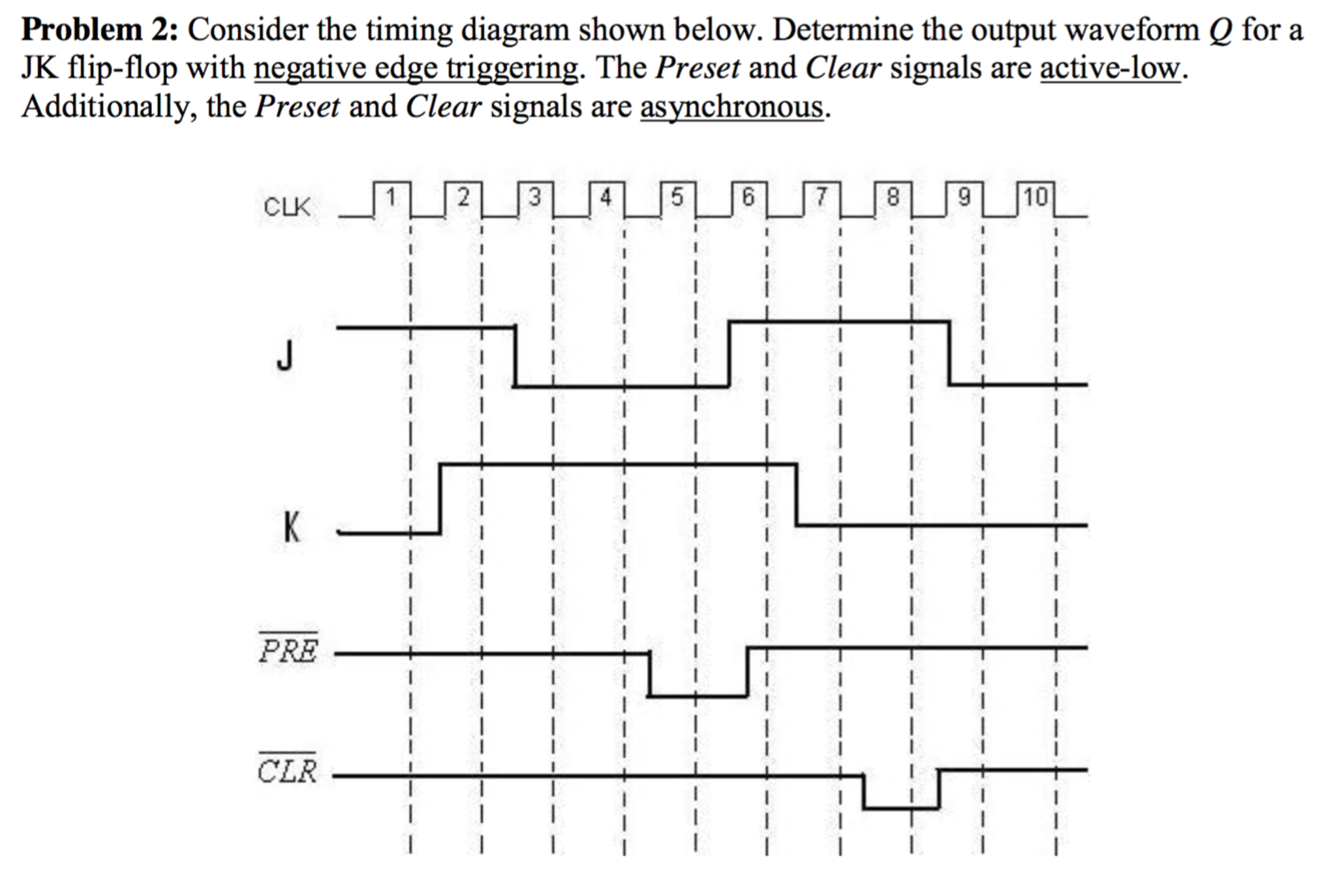
Solved 2. consider the timing diagram shown below. determine ...
Bagaimana cara kerja flip-flop jk yang dipicu tepi negatif? - quora
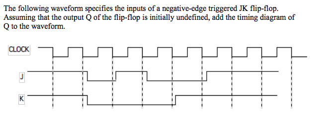
Solved the following waveform specifies the inputs of a | chegg.com
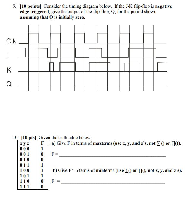
Solved) : 9 10 points consider timing diagram j k flip flop ...
Solved 1. consider the negative edge triggered jk flip-flop ...

D flip flop timing diagram - slide share

Jk flip flop: what is it? (truth table & timing diagram ...
Edge-triggered j-k flip-flop
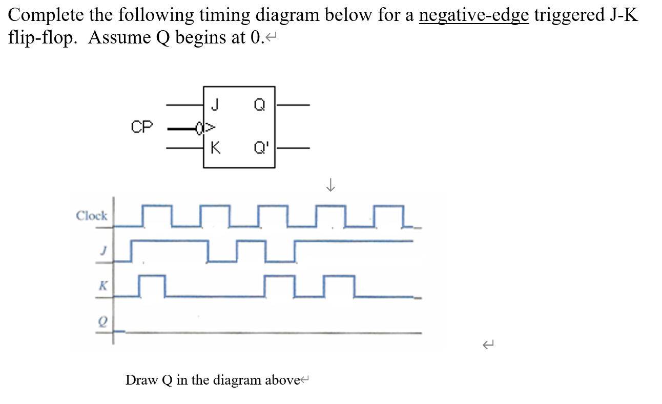
Solved complete the following timing diagram below for a | chegg.com
Digital electronics workshop - ppt download

Jk flip flop and the master-slave jk flip flop tutorial
Edge-triggered latches: flip-flops - instrumentationtools
Edge-triggered latches: flip-flops | multivibrators | electronics ...
Answered: a) complete the timing diagram for the… | bartleby
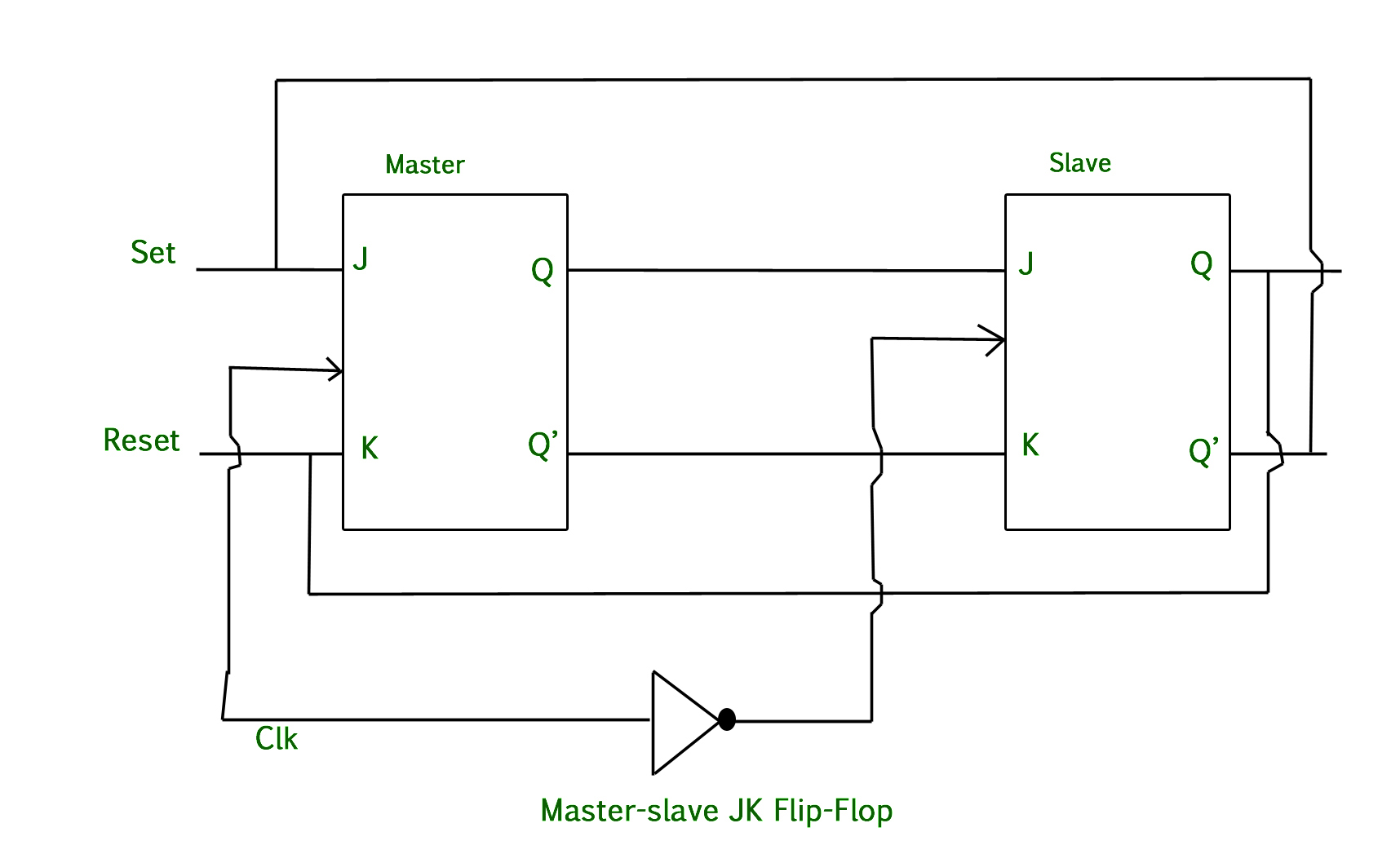
Master-slave jk flip flop - geeksforgeeks

Negative edge triggered d flip flop truth table - hogikayla
Solved) - 1. fill in the timing diagram for a falling-edge ...
Solved 7. (timing diagram for a positive-edge-triggered jk | chegg.com
Jk flip-flop timing diagram positive edge triggering - electrical ...
0 Response to "40 negative edge triggered jk flip flop timing diagram"
Post a Comment