37 mercruiser trim sender wiring diagram
Mercruiser Trim Sender Wiring Diagram - mercruiser alpha one trim sender wiring diagram, mercruiser digital trim sender wiring diagram, mercruiser trim position sender wiring diagram, Every electric arrangement is made up of various unique components. Each part should be placed and connected with different parts in specific way. Otherwise, the structure will not function as it should be. According to earlier, the traces at a Mercruiser Trim Sender Wiring Diagram signifies wires. Sometimes, the wires will cross. However, it doesn't imply link between the cables. Injunction of two wires is usually indicated by black dot to the intersection of two lines. There will be main lines which are represented by L1, L2, L3, and so on.
Mercruiser Wiring Diagram | Wirings Diagram Feb 21, 2019Mercruiser Wiring Diagram - mercruiser 140 wiring diagram, mercruiser alternator wiring diagram, mercruiser ignition wiring diagram, Every electric structure consists of various distinct parts. this switch could be bad or out of adjustment. this switch interrupts the ignition system for a split second when you are …

Mercruiser trim sender wiring diagram
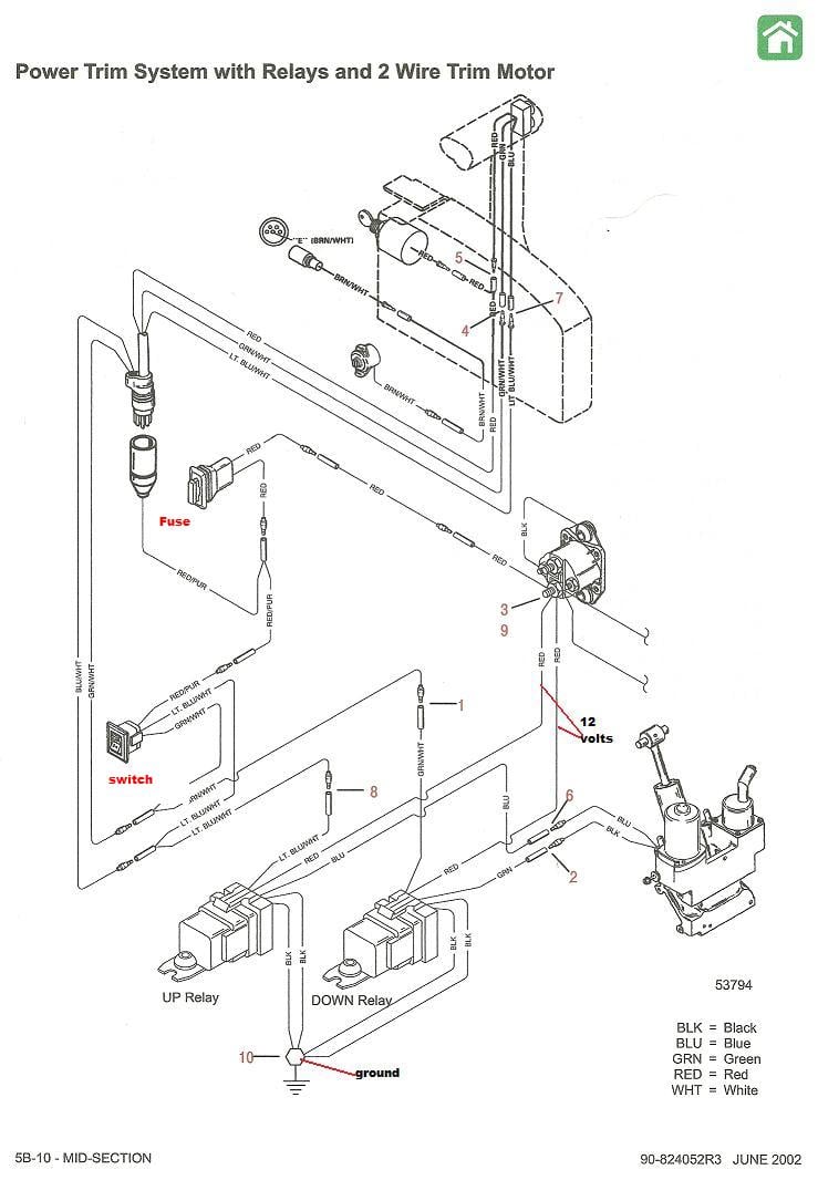
Mercury Trim Motor Wiring Diagram Download - Collections Of Mercruiser Trim solenoid Wiring Diagram Yahoo Image Search Results. Galericanna Wp Content 2018 07 Mercury. Tilt and Trim Switch Wiring Diagram Awesome Technical Information. Tilt and Trim Switch Wiring Diagram Best Trim and Hydraulics Need. Page 117: Power Trim Wiring Diagram WIRING DIAGRAMS Power Trim Wiring Diagram Tach. Connector Trim Pump and Motor Key Switch Assembly DOWN Solenoid Trim Switch UP Solenoid Trim Sender Bottom Cowl Switch Start Solenoid 20 Ampere Fuse To Battery Engine Harness To Alternator Remote Control Harness Page 2D-2 90-855347R1 JANUARY 1999... Leave a Comment / Tips & Guide / By temp switch instrument cluster motor trim, 115hp 1975 mercury power trim fluid level 1990 90hp yamaha 2 stroke power tilt amp trim service 1995 mercruiser 7 4 trim switch wiring diagram 1999 40 hp yamaha tilt and trim fluid change 1999 60 hp yamaha tilt and trim fluid fil 2005 40 hp yahama weak power trim how to fi 2006 yamaha …
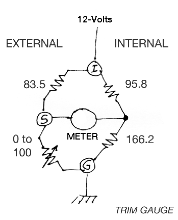
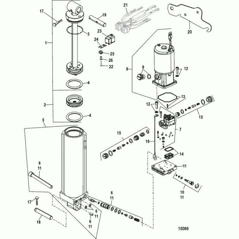
Mercruiser trim sender wiring diagram. Tilt and Trim Switch Wiring Diagram Best Trim and Hydraulics Need. Marine does not of the shock pistons. This Factory Service Repair Manual offers all the service and repair information about Mercury Mariner 45hp-225hp Outboards. 95 Mercury/mariner New Oem Power Trim And Tilt Kit 822344a13 25hp 40hp 45hp 50hp 4stk Mercury Mariner 3 Wire Power Hydraulic Motor … Yamaha Trim Sender Wiring Ribnet Forums. Merc trim gauge sender smartcraft offsonly com mercruiser wiring the power tilt motor and wire harness e tec rigging moderated yamaha ribnet forums mercury 2 diagram 898r from 1983 up troubleshooting drive trims down but for 383 analog conversion marine engine 90 pontoon limit wires club four coming sensors resistor i have a 150 hp blackmax sending unit ... 4e - 2 - wiring diagrams 90-816462 2-695 wiring diagrams 3.0l engine wiring diagram (breaker points ignition) 50726 choke shift interrupt switch alternator optional audio warning water temperature heat switch water temperature sender optional oil pressure switch terminal block engine ground ground stud on engine flywheel housing ground screw on ... This MerCruiser power trim and tilt system is electro-hydraulically operated. Its electrical sub-system consists of a power trim control panel or handle, a pump motor and a trim limit switch, with connecting wiring. Some models may also be equipped with a trim indicator sender. Figure 1 shows a typical system. The hydraulic sub-system contains ...
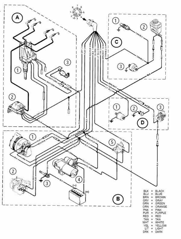
Some models may also be equipped with a trim indicator sender. 90 806535940 893 wiring diagrams 4d 1 wiring colors for mercruiser bia color code where used black all grounds brown reference electrode mercathode orange anode electrode mercathode lt. Or handle a pump motor and a trim limit switch with connecting wiring. Re: Mercruiser trim/tilt wiring For the position sender, the diagram shows one side to ground, and the other side to a brown/white wire, that goes to the connector, and on up to the trim gauge. Look on the back of the gauge and see if there is a br/w wire there. R rjs65 Cadet Joined Jul 25, 2009 Messages 8 Aug 22, 2010 #7 Mercruiser L Engine Wiring Diagrams. A - Ignition Components 1 - Distributor 2 - Ignition Coil 3 - Shift Cutout Switch. B - Starting Charging and Choke Components 1 - Alternator 2 - Electric Choke 3 - Trim Sender. Buy the products and parts you need Buy Parts and Products. or Oildyne hydraulic pump, the trim cylinders, a reverse ... Mercruiser Trim Sender Wiring The Hull Truth Boating And Fishing Forum. Power Trim Tilt Motor And Wire Harness Kit P N 584107 Crowley Marine. Viewing A Thread 2 Wire Motor Trim Wiring Diagram. Mercury Trim Gauge Mercruiser Outboard Quicksilver 79 895292a01 Gauges Wiring Bottom Line Isle Of Man. I Have A Mercruiser 898r From 1983 The Trim Up ...
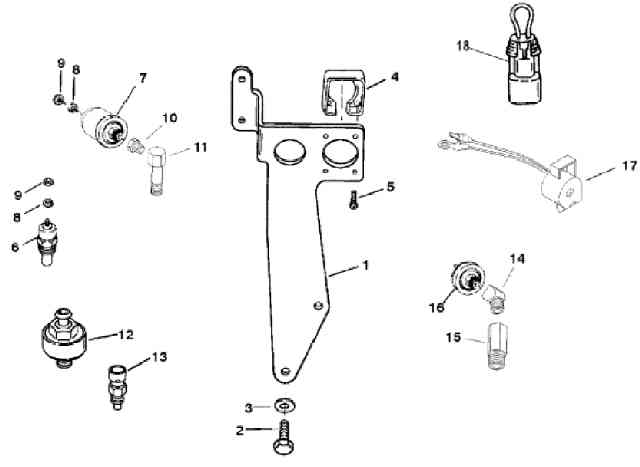
The Trim Sender Switch is on the Starboard side of the Gimbal Ring. The newer model Trim Sender switches have a "TP' or "Trim Position" embossed in the plastic(see image below). Each switch has a wire harness that is routed behind the Bell Housing after which it passes through a small hole in the Gimbal Housing shroud and into the bilge. Step by step instructions detailing how to remove a Mercruiser Bravo sterndrive to repalce the trim position sender and trim limit switches. Trim/Sender Limit Switches. This replaces MerCruiser p/n 805320A1. It will fit all MerCruiser #1 drives made from 1975 to Date including Alpha One, Gen II and Bravo. It cannot be used on boats which have dual station gauges, such as 1 in the cockpit & 1 more on the fly bridge. The wires should 2 pairs. One pair for trim limit and the other pair for trim sender.Can you determine the pairs? The trim limit will be the 2 male and the other pair will be trim sender. The trim limit will connect to the blue and purple wires near the trim pump. The trim sender wire will be a brown wire and a ground black. Here is a diagram.
navigation map
Mercruiser Electrical Diagrams Engines, Drives And Quicksilver Instruments ... wire is taped back at instrument end If installing on boat that is equipped with MerCruiser stern drive BROWNWHITE wire is connected to trim sender terminal block If installing on BROWNWHITE wire is taped back at engine end or it may be used for an accessory limit 5 ...

pink flowers in tilt shift lens
Tachometer not working mercury outboard

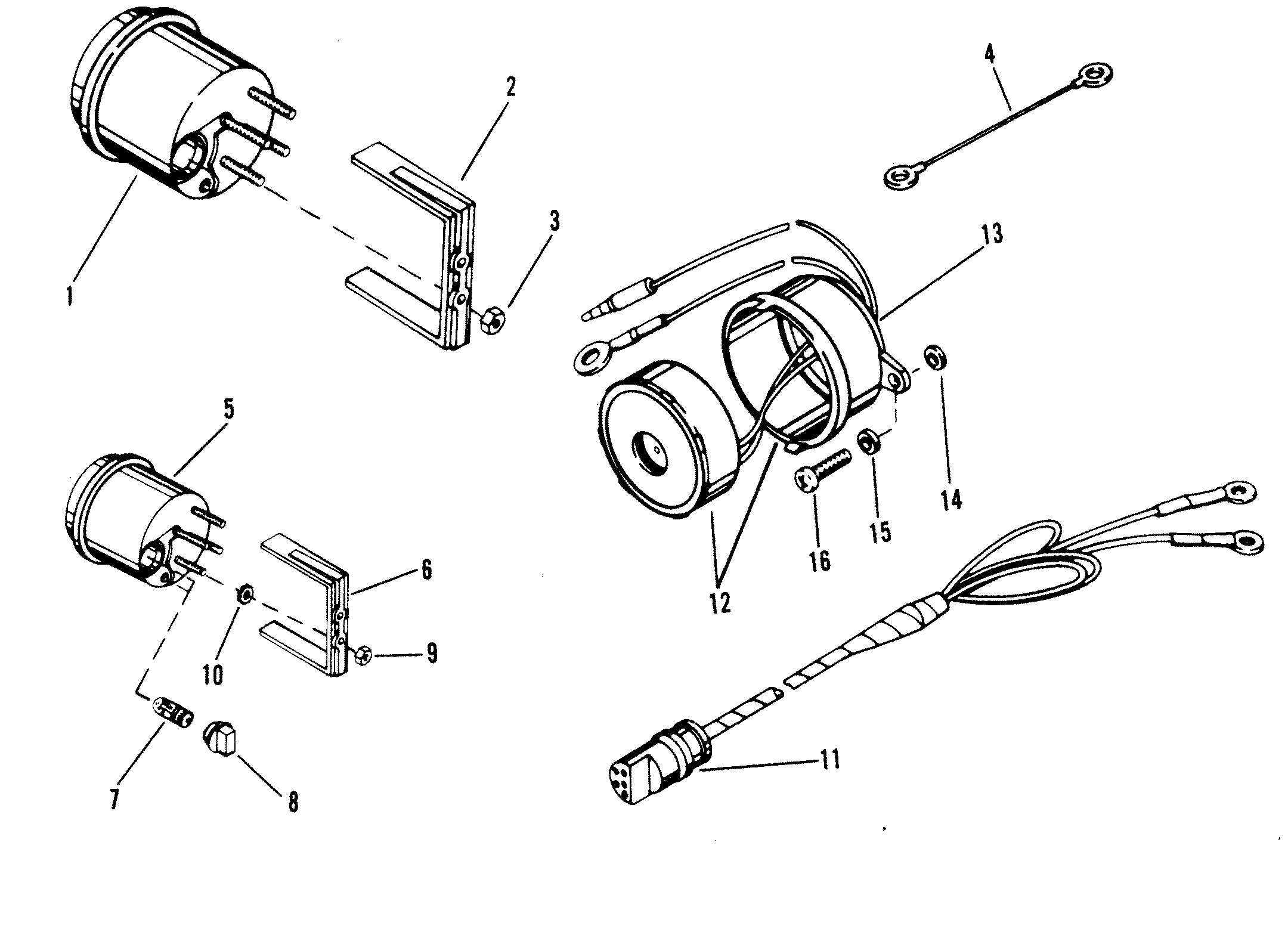
Mercury Quicksilver 863187A 1 - SENDER ASSEMBLY T QPD=NO NLA
805320A1 TRIM SENDER AND TRIM LIMIT SWITCH KIT Page 3 of 10 7. Pull back on bell housing and rotate it 90 degrees to gain access to the trim wire retainer bolt. 23363 a a-Bell Housing 8. Remove trim wire retainer. 70197 a b a-Clamp b-Bolt 9. Disconnect trim limit switch wires at the power trim pump. Also, disconnect trim sender wires at the ...
Mercruiser Trim Sender Wiring Diagram - Atkinsjewelry
Diy mercruiser alpha/bravo trim sender install under 30 minutes, not for new boat but easy if you have an older boat and don't want to spend a lot pulling ev...

Mercruiser Trim Sender Wiring Diagram - Free Wiring Diagram
Scroll down to explore all 10 images uploded under Mercruiser Wiring Diagram's gallery . The Trim Sender Switch is used to send a signal to the Trim Gauge so you can see the level of the drive. Description: The Trim Senders are located on either side of the Gimbal Ring. The Trim Limit Switch is mounted to the Port side of the Gimbal Ring.

7 Mercruiser Trim Sender Wiring Diagram - Free Wiring Diagram Source
6 - 0 Power Trim. Trim System Wiring Diagrams. 6 - 10 Power Trim Hydraulic Schematic. 6 - 13 .. c - "UP" Solenoid d - Amp Fuse. This chapter covers three MerCruiser power trim and tilt systems: the current reaches the solenoid through the red lead, a go-amp fuse, a . Reconnect wires to back of new switch/sender. .

gray concrete statue of a man
Mercruiser Trim Sender Wiring Diagram | Wiring Diagram - Mercruiser Trim Sender Wiring Diagram Wiring Diagram contains several comprehensive illustrations that present the connection of varied items. It contains instructions and diagrams for different varieties of wiring techniques and other things like lights, home windows, and so forth.

Wiring Diagram For 3 Button Single Solenoid Trim Pump For ...
Re: Mercruiser Trim sender/limit wiring help. Before you tear anything apart or replace wiring and switches, test it out; firstby visual inspection by pulling back and forth on the wires while operating theswitches and then test with a meter. At the commander switches ,the red wirewill always have 12 volts.

Wiring Diagram For 3 Button Single Solenoid Trim Pump For Mercruiser
One sender is for the Trim Gauge and the other sender is for the Trim Limit. This Single Lever dual action control from UFlex operates both throttle and shift. ). Start by pulling your trim tabs up fully (if you have tabs). Oct 16, 2013 · Rejected Take Off (RTO) after 80 knots called - Activation of either reverse thrust lever and throttle to idle will extend spoilers (if RTO armed). Oct 24 ...

silver and black round coins
- Youtube - Mercruiser Trim Sender Wiring Diagram Wiring Diagram consists of numerous comprehensive illustrations that show the relationship of various items. It includes directions and diagrams for various kinds of wiring techniques and other products like lights, home windows, and so forth.

pink and yellow rose in bloom during daytime
Mercury-Mercruiser 805320A03 Power Trim Sender Kit Alpha/Bravo. 805320A03 Power Trim Sender kit for Alpha and Bravo Drives (Analog) This is a genuine Mercury Marine factory OEM part, not aftermarket Please check our current stock level and order below or use the Contact Us form at the bottom of the page for any questions

Mercruiser 350 Mag Wiring Diagram - Wiring Diagram
Johnson tilt and trim troubleshooting

gray rope on brown wooden table
engine-mercruiser 325 with water temperatureswitch and trim sender orange distributor purple imally closed ierse5 interlock normally closed trim limit blue)t switch ition wi oil pressure transistor voltage regulator bahery i f batt. grnd. switch (optional) male connector pinand water temp. sender water temp. switch instrument cluster motor trim ...
Wiring Diagram For A 190 Mercruiser Trim Double Solenoid
Aug 25, · Re: Mercruiser trim/tilt wiring For the position sender, the diagram shows one side to ground, and the other side to a brown/white wire, that goes to the connector, and on up to the trim gauge. Look on the back of the gauge and see if there is a br/w wire there. The Trim Limit Switch is mounted to the Port side of the Gimbal Ring.

26 Mercruiser Trim Gauge Wiring Diagram - Wiring Diagram List
Mercruiser power trim wiring schematic perfprotech com mercury pump diagram is this right offsonly hydraulic and control panel tilt serial range 120 140 1967 1969 2062141 thru 2791956 crowley marine sender the hull truth boating fishing forum sterndrive diode module for duel engines wire harness sel engine repair sae j1171 club sea ray 3 0 alpha one solenoid… Read …

Mercruiser Trim Motor Wiring Diagram - Wiring Diagram Schemas
View and Download Mercury 150 EFI service manual online. Electronic Fuel Injection,. 150 EFI engine pdf manual download. Also for: 175 efi, 200 efi, 150xri, 175xri, 200xri, 0t409000.

white and blue dragon figurine
Power Tilt And Trim Wiring - Wiring Diagram Schematic Name - Mercruiser Trim Sender Wiring Diagram Wiring Diagram consists of many detailed illustrations that present the relationship of varied products. It includes instructions and diagrams for various kinds of wiring strategies and other items like lights, home windows, and so on.
mercruiser trim sender wiring - The Hull Truth - Boating and Fishing Forum
Mercruiser Trim Sender Wiring Diagram. January 22, 2019. April 12, 2020. · Wiring Diagram. by Anna R. Higginbotham. mercruiser trim sender wiring diagram - You will want an extensive, professional, and easy to know Wiring Diagram. With such an illustrative guide, you will have the ability to troubleshoot, avoid, and full your projects with ...
35 Mercruiser Trim Sender Wiring Diagram - Wiring Diagram List
Find your Mercruiser, Mercury and Mercury Racing sterndrive, inboard, diesel or gas engine parts here with our detailed diagrams, parts drawings, images and parts breakdowns. Select your product then select your serial number range to locate your parts diagrams. Order online for discounted pricing.
31 Mercruiser Tilt Trim Wiring Diagram - Wiring Diagram List
+1 on the trim senders. It isn't your gauge, it isn't your wiring. Unless you want to pull the drive, get a special tool, and then remove the bellhousing, LEAVE IT ALONE. Trim senders (especially on a merc) are useless. All they do is eat up $ and they always break. They are a pain in the you know what!

Where can i find a wiring diagram for a trim pump with a single solenoid and trim sensors on the ...
Leave a Comment / Tips & Guide / By temp switch instrument cluster motor trim, 115hp 1975 mercury power trim fluid level 1990 90hp yamaha 2 stroke power tilt amp trim service 1995 mercruiser 7 4 trim switch wiring diagram 1999 40 hp yamaha tilt and trim fluid change 1999 60 hp yamaha tilt and trim fluid fil 2005 40 hp yahama weak power trim how to fi 2006 yamaha …

Mercruiser Trim Sender Wiring Diagram - QUIRKYINSANITY
Page 117: Power Trim Wiring Diagram WIRING DIAGRAMS Power Trim Wiring Diagram Tach. Connector Trim Pump and Motor Key Switch Assembly DOWN Solenoid Trim Switch UP Solenoid Trim Sender Bottom Cowl Switch Start Solenoid 20 Ampere Fuse To Battery Engine Harness To Alternator Remote Control Harness Page 2D-2 90-855347R1 JANUARY 1999...
Wiring Diagram For A 190 Mercruiser Trim Double Solenoid
Mercury Trim Motor Wiring Diagram Download - Collections Of Mercruiser Trim solenoid Wiring Diagram Yahoo Image Search Results. Galericanna Wp Content 2018 07 Mercury. Tilt and Trim Switch Wiring Diagram Awesome Technical Information. Tilt and Trim Switch Wiring Diagram Best Trim and Hydraulics Need.
![[KF_3991] Trim Pump Wiring Schematic Wiring](https://static-resources.imageservice.cloud/678728/single-solenoid-trim-pump-wiring-page-1-iboats-boating-forums.jpg)
[KF_3991] Trim Pump Wiring Schematic Wiring
Mercruiser Power Trim Wiring Diagram - Wiring Diagram Schema - Fuel Gauge Sending Unit Wiring ...

32 Mercruiser Trim Sender Wiring Diagram - Wiring Diagram Database
Quicksilver Trim Switch Wiring Diagram

I'm in the process of changing the lcd multi gauges for my 1995 175 outboards with a new faria ...

Trim Sender Wire On 500 Efi Hp Mercury Racing | My Wiring DIagram

WIRING DIAGRAM FOR A 1984 24 FOOT RENKEN BOAT

blue and green thread on brown wooden shelf

MerCruiser 57322T Trim Sender Wire Cover Retainer Gimbal Housing Alpha - NLA Marine

MerCruiser 19' 8-Pin Wire Wiring Harness Dash to Motor Gauges 5.7L 4.3 - NLA Marine

Mercruiser Trim Sender Wiring Diagram - Atkinsjewelry

I am looking at a 1987 Wellcraft with a 5.7 Mercruiser inboard outdrive engine. It's been out of ...

Tilt And Trim Wiring Diagram - Complete Wiring Schemas

MerCruiser 57322T Trim Sender Wire Cover Retainer Gimbal Housing Alpha One | eBay
0 Response to "37 mercruiser trim sender wiring diagram"
Post a Comment