38 3 phase phasor diagram
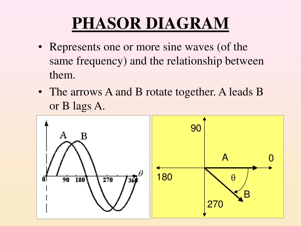
Time phasor diagrams for one phase winding under no-load and loaded conditions are shown in Fig. 9.17 A and B, respectively, and in each case the time phasors of the flux linkage have been shifted to the right to avoid congestion with the voltages and current.These flux phasors can be compared with the space vectors shown in Fig. 9.10.Once again, resistance has been neglected in the interests ... Figure 1 Phase sequence of a three-phase source. Once we have drawn a phasor diagram for the voltages in a 3φ system, we can easily read the phase sequence from the phasor diagram. Since the direction of rotation of a phasor is counterclockwise, the phase sequence is the order in which the voltage phasors would pass the reference axis if they ...
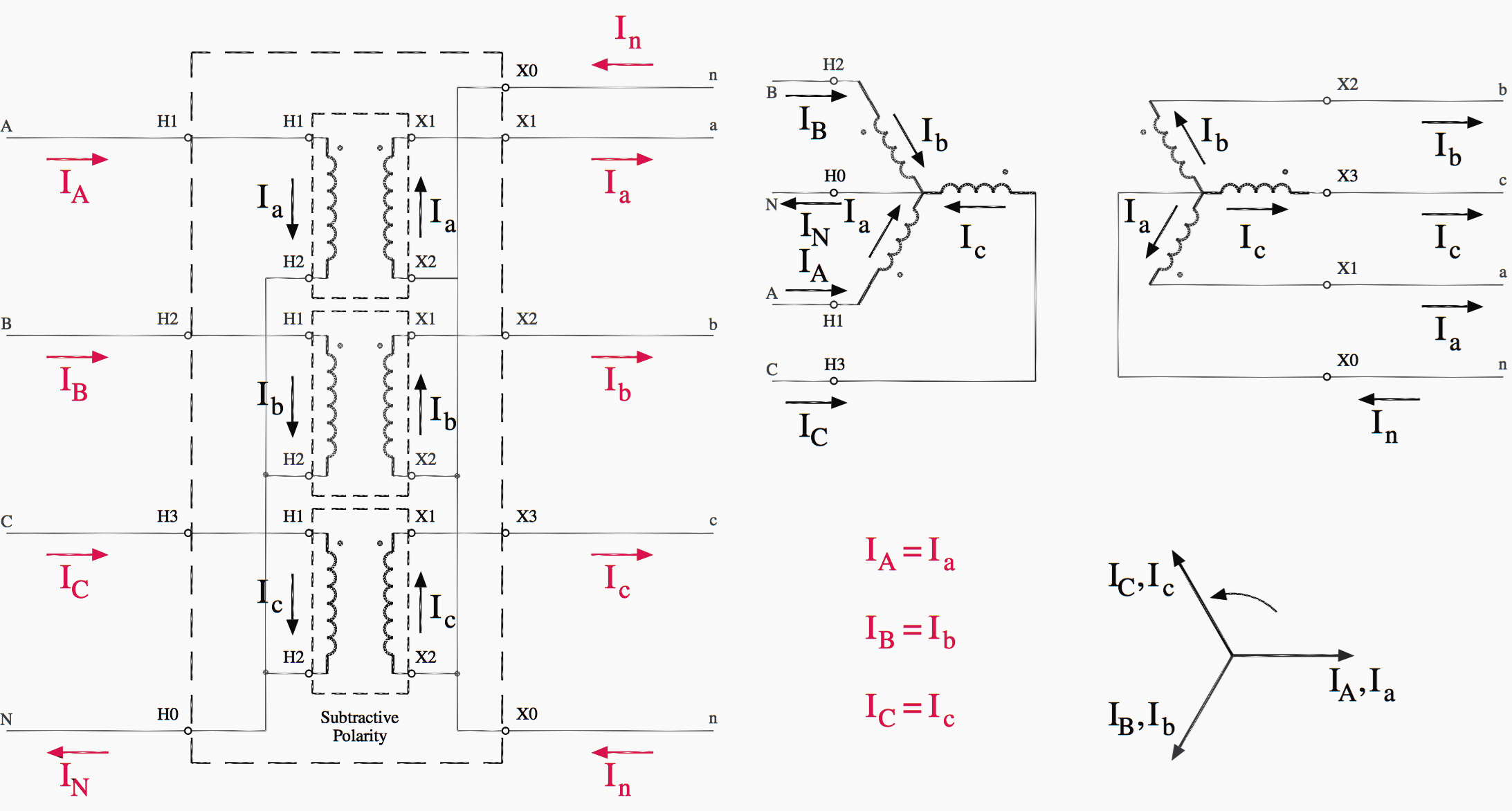
A three-phase transformer is built for a specific connection and voltage transformation and the unit will have a nameplate with the internal connections shown. When a single unit or bank of three is used, there are four types of connections. The four basic connections are: Y-Y, Y-∆, ∆-Y, and ∆-∆. The first symbol indicates the connection of the primary, and the second symbol is the ...

3 phase phasor diagram
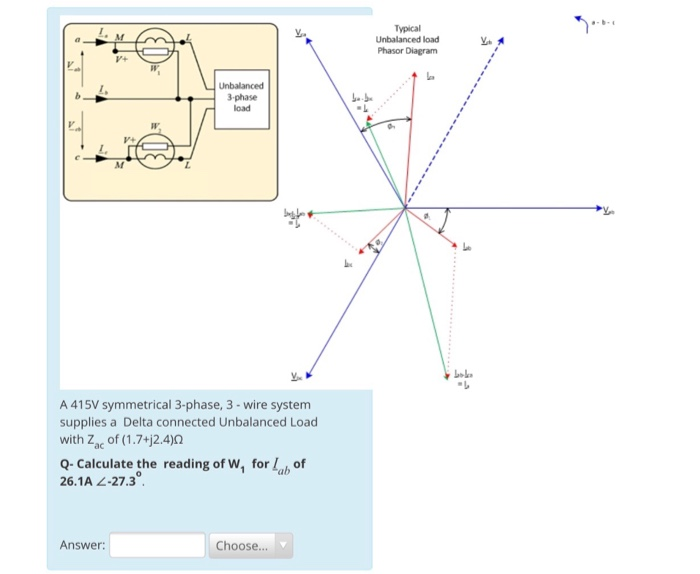
Three-Phase to Twelve-Phase Transformers: Circuit Diagram and Phasor Diagram. Digital Electronics Electron Electronics & Electrical. The circuit arrangement of the transformers for three-to-twelve phase transformation is shown in the figure. Here, two banks of three 1-phase transformers or two 3-phase transformers are required. Phasor Diagram of Three Phase Induction Motor In a 3-phase induction motor, the stator winding is connected to 3-phase supply and the rotor winding is short-circuited. The energy is transferred magnetically from the stator winding to the short-circuited, rotor winding. Assuming balance three phase supply connected to an unbalance three phase load, the voltages and currents at the load end can be written as shown in (1). Fig. 1 shows the corresponding phasor ...
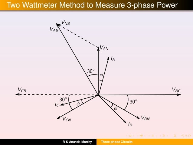
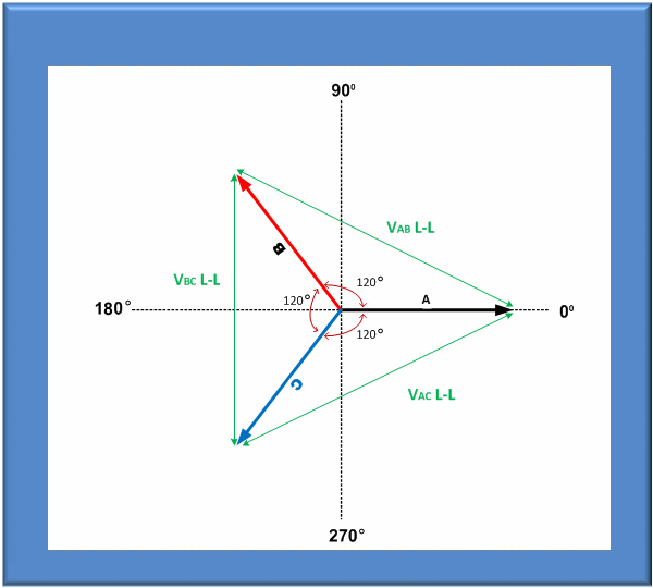
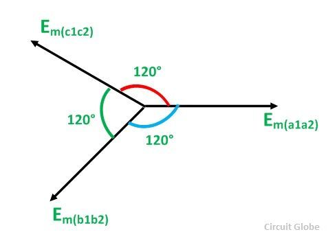
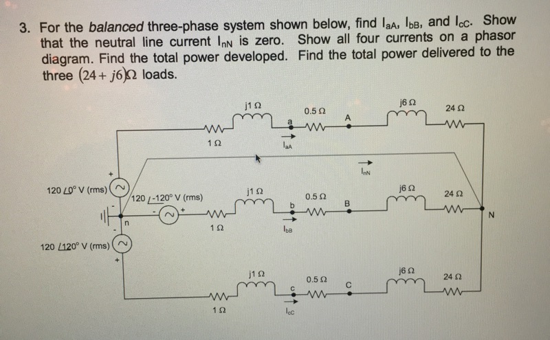
3 phase phasor diagram. The 3-Phase Phasor Diagram Previously we have only looked at single-phase AC waveforms where a single multi-turn coil rotates within a magnetic field. But if three identical coils each with the same number of coil turns are placed at an electrical angle of 120 o to each other on the same rotor shaft, a three-phase voltage supply would be generated. Given a balanced three-phase system, the currents flowing into the delta-connected load can be defined by The resulting phasor diagram relating the line currents to the delta-connected load currents follows the same pattern as the delta-connected source. Phasor diagram display The most powerful tool on Fluke’s three phase analyzers to make this check is the phasor diagram display. In one screen, you can quickly see whether you have connected up the voltage and current in the right sequence and that the current sensors are correctly measuring the direction of the current entering the load or ... 2. Draw the one-line diagram for phase a, recognizing that phase a has one third of the P and Q. 3. Solve the one-line diagram for line-to-neutral voltages and line currents. 4. If needed, compute line-to-neutral voltages and line currents for phases b and c using the ±120° relationships. 5. If needed, compute line-to-line voltages and delta ...
Assuming balance three phase supply connected to an unbalance three phase load, the voltages and currents at the load end can be written as shown in (1). Fig. 1 shows the corresponding phasor ... Phasor Diagram of Three Phase Induction Motor In a 3-phase induction motor, the stator winding is connected to 3-phase supply and the rotor winding is short-circuited. The energy is transferred magnetically from the stator winding to the short-circuited, rotor winding. Three-Phase to Twelve-Phase Transformers: Circuit Diagram and Phasor Diagram. Digital Electronics Electron Electronics & Electrical. The circuit arrangement of the transformers for three-to-twelve phase transformation is shown in the figure. Here, two banks of three 1-phase transformers or two 3-phase transformers are required.








![[DIAGRAM] 3 Phase Electrical Phasor Diagram Wiring ...](https://electricallive.com/wp-content/uploads/2018/04/27.jpeg)



0 Response to "38 3 phase phasor diagram"
Post a Comment