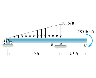
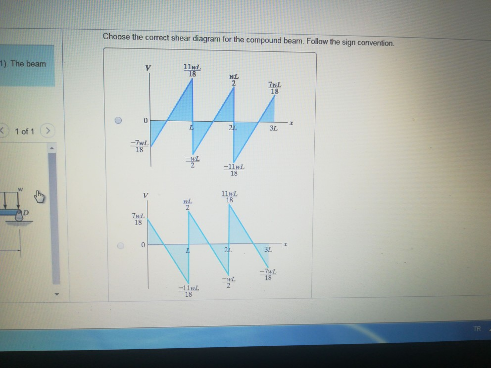
38 choose the correct shear diagram for the beam. follow the sign convention.
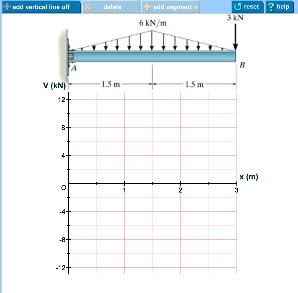
Use beam theory sign convention for shear force and bending moment. V+ V+ M+ M+ Beam Stiffness Step 4 - Derive the Element Stiffness Matrix and Equations Using beam theory sign convention for shear force and bending moment we obtain the following equations: 3 1112233 0 y 12 6 12 6 x dv EI fVEI v L v L dx L 3 2112233 The support at A offers no resistance to vertical load. Part A Choose the correct shear diagram for the beam. Follow the sign convention. Choose the correct ...
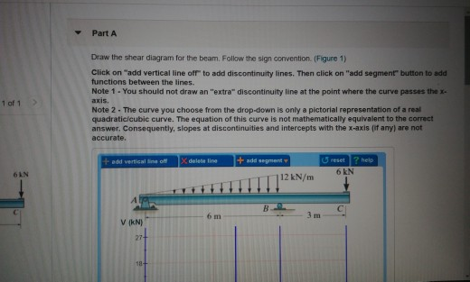
Shear Diagram: Moment Diagram: 1. Point loads cause a vertical jump in the shear diagram. The direction of the jump is the same as the sign of the point load. 2. Udl result in a straight, sloped line on the shear diagram. 3. The shear diagram is horizontal for distances along the beam with no applied load. 4.

Choose the correct shear diagram for the beam. follow the sign convention.
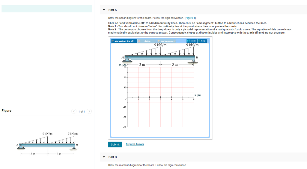
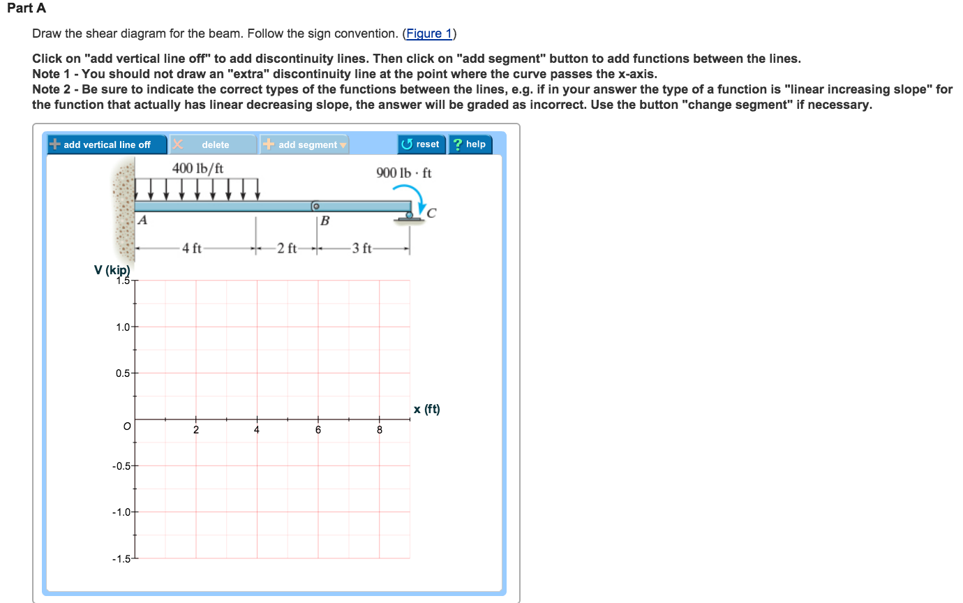
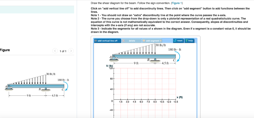
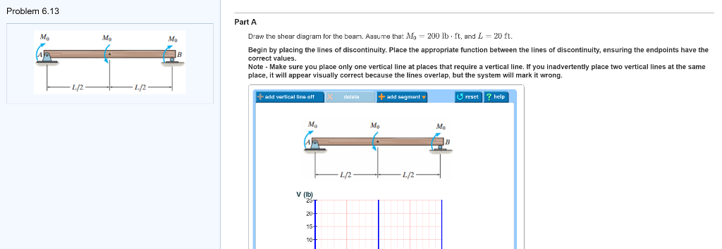
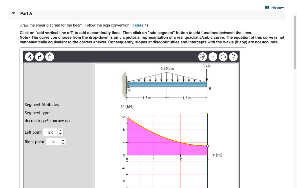
F.1 (b), the positive sign convention is (a) tension axial force, (b) shear forces that produce clockwise momentsand (c) bending moments that result in tension stresses in the interior frame fibers. The sign convention of F.1(b) can be seen to be equivalent to the beam sign convention rotating columns AB and CD to line up with beam BC. 27 For the derivation of the relations among w, V, and M, consider a simply supported beam subjected to a uniformly distributed load throughout its length, as shown in the figure below.Let the shear force and bending moment at a section located at a distance of x from the left support be V and M, respectively, and at a section x + dx be V + dV and M + dM, respectively. 16.07.2016 · Part A Draw the shear diagram for the beam. Follow the sign convention. (Figure 1) Click on "add vertical line off" to add discontinuity lines. Then click on "add segment" button to add functions between the lines. Note 1 - Draw a vertical line to denote local maximum or minimum. Note 2 - The curve you choose from the drop-down is only a pictorial
Choose the correct shear diagram for the beam. follow the sign convention.. Draw the shear diagram for the beam. Follow the sign convention. Then click on "add segment" button to add functions between the lines. Note 1- Make sure you place only one vertical line at places that require a vertical line. Note 2 - You should not draw an "extra" discontinuity line at the point where the curve passes the x-axis. F.1 (b), the positive sign convention is (a) tension axial force, (b) shear forces that produce clockwise moments and (c) bending moments that result in tension stresses in the interior frame fibers. The sign convention of F.1(b) can be seen to be equivalent to the beam sign convention rotating columns AB and CD to line up with beam BC. B) Draw the moment diagram for the beam. Follow the sign convention. Show transcribed image text. Expert Answer. A. Draw the shear diagram for the beam. Follow the sign convention. B. Draw the moment diagram for the beam. The units of the shear and moment diagrams must be in kips and kips*ft, respectively. Please show the steps. Thank you!
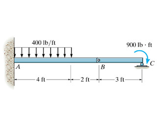
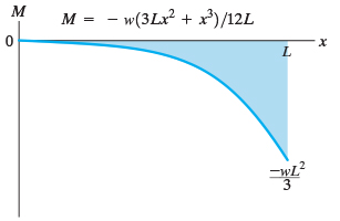
Problem 4.3-1 Calculate the shear force V and bending moment M at a cross section just to the left of the 1600-lb load acting on the simple beam AB shown in the figure. Solution 4.3-1 Simple beam 4 Shear Forces and Bending Moments 259 AB 800 lb 1600 lb 120 in. 30 in. 60 in. 30 in. M A 0: R B 1400lb M B 0: R A 1000lb Free-body diagram of segment ... Choose the correct moment diagram for the beam. Follow the sign convention. It is a cubic curve that starts at zero and has a negative increasing slope. ... Choose the correct shear diagram for the beam. Follow the sign convention. x=1.005 m. obtain the shear force and bending moment diagrams for the beam. The shear force and bending moment diagrams are convenient visual references to the internal forces in a beam; in particular, they identify the maximum values of V and M. a. Sign conventions ( )k/lblihi/h i Figure 4.3 Sign conventions for external loads; shear force, and bending moment. b. Procedure for … As for S.F., a convenient sign convention must be adopted. b. Bending moment (B.M.) sign convention Clockwise moments to the left and counterclockwise to the right are positive. Thus Fig. a - shows a positive bending moment system resulting in sagging of the beam at X-X and Fig. b- illustrates a negative B.M. system with its associated hogging ...
(Figure 1) Part B> Draw the moment diagram for the beam. Follow the sign convention. Please help! Thank you! This problem has been solved! See the answer ... 1 Answer to Consider the beam shown in (Figure 1) . Follow the sign convention. Draw the shear diagram for the beam. Draw the bending moment diagram for the beam. 2 k 2k 2 k 2k 4 ft 4 ft 4 ft 4 ft 4 ft Consider the beam shown in (Figure 1) . Follow the sign convention. Draw the shear diagram for the beam. Draw the moment diagram for the beam. Fundamental Problem 4.13 Considor tho beam shown in Eguro 10. Follow tho sign convention. 2 m 2 m Part A... Sep 12, 2021 · PART A Draw the shear diagram for the beam. Follow the sign convention. (Figure 1) Click on "add vertical line off" to add discontinuity lines. Then click on "add segment" button to add functions between the lines. Note 1 - You should not draw an "extra" discontinuity line at the point where the curve passes the x-axis.
Solved: A. Draw The Shear Diagram For The Beam. Follow The ...
26.10.2017 · Question: Problem 7.59 Part A Draw the shear diagram for the beam. Follow the sign convention. (Figure 1) Click on "add vertical line off" to add discontinuity lines. Then click on "add segment" button to add functions between the lines. Note 1- You should not draw an "extra" discontinuity line at the point where the curve passes the x-axis Note 2 The curve you choose
Solved: Part A Draw The Shear Diagram For The Beam. Follow ...
The support at A offers no resistance to vertical load Choose the correct shear diagram for the beam. Follow the sign convention Wol Figure Previous Answers ...
Solved: 8 Of 8 Draw The Shear Diagram For The Beam. Follow ...
Then, drawing the moment diagram using the shear sign convention gives a graph with what you have described as the "positive bending moment above the beam". The example in the book is easy to follow, put a single point load in the center of a simple beam and draw the diagrams by hand.
Solved: Part A Draw The Shear Diagram For The Beam Follow ...
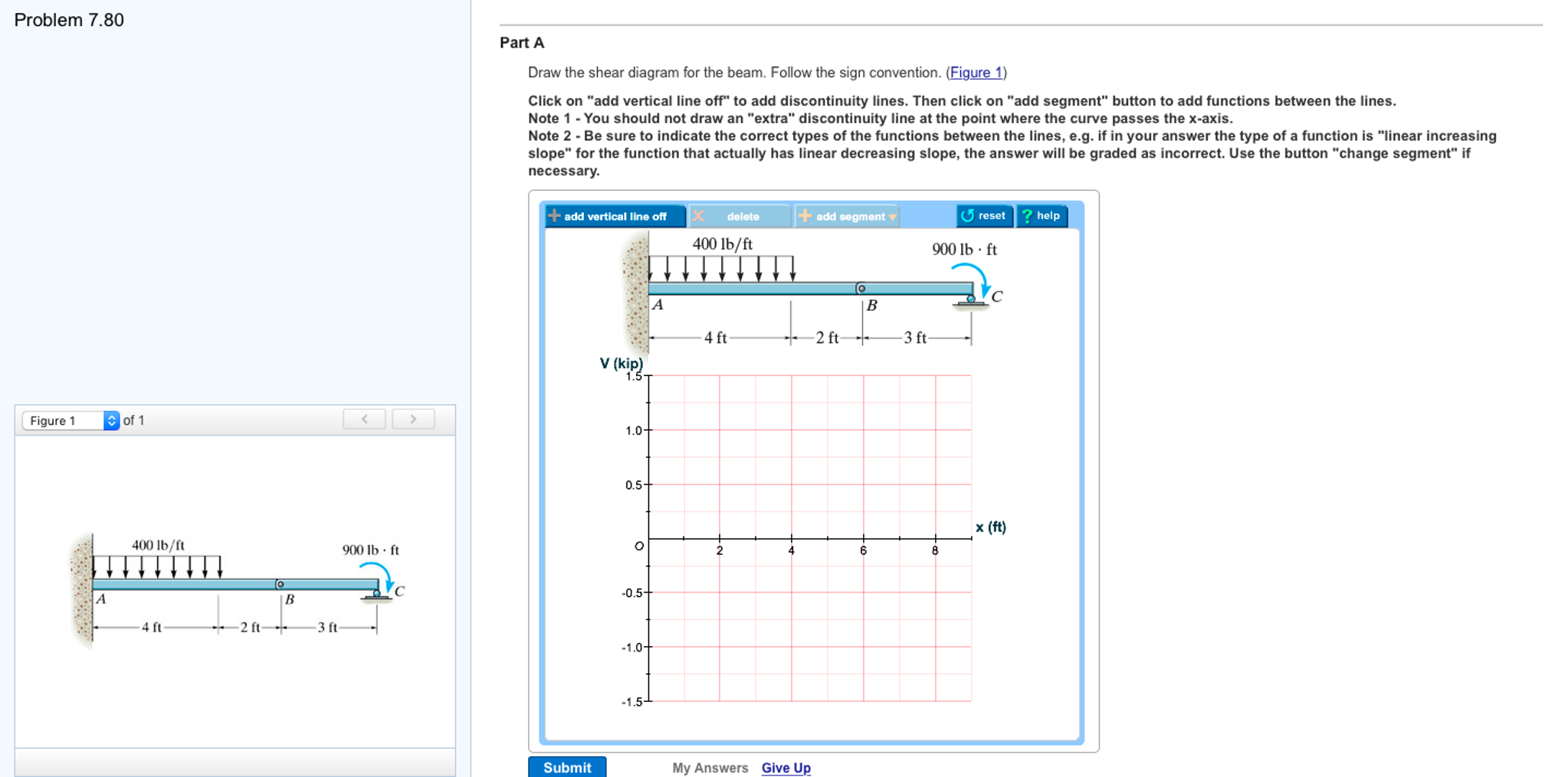
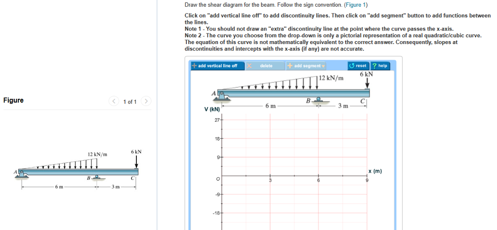
Part A. Draw the shear diagram for the beam. Follow the sign convention. (Figure 1) Click on "add vertical line off" to add discontinuity lines. Then click on "add segment" button to add functions between the lines. Note 1 - You should not draw an "extra" discontinuity line at the point where the curve passes the x-axis.
Solved: Draw The Shear Diagram For The Beam. Follow The Si ...
When the shear diagram is increasing, the moment diagram is concave upward. When the shear diagram is decreasing, the moment diagram is concave downward. Sign Convention The customary sign conventions for shearing force and bending moment are represented by the figures below. A force that tends to bend the beam downward is said to produce a ...
Solved: Part Draw The Shear Diagram For The Beam. Follow T ...
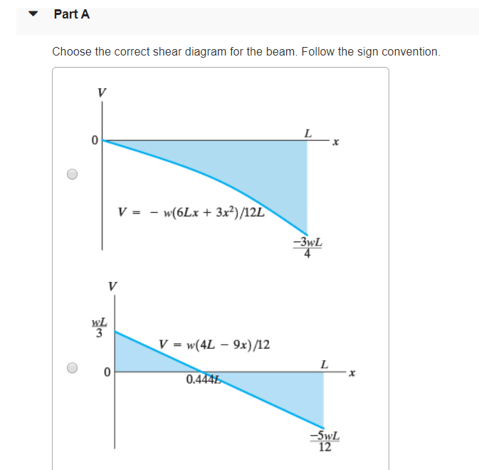
20.04.2020 · Transcribed image text: Consider the beam shown in (Figure 1). Choose the correct shear diagram for the beam. Follow the sign convention V - - w (6Lx + 3x)/12L -32 V = w (4L2 - 6Lx - 3x?)/12L 0.528. Figure 1 of 1 > V = - 3wx/4 -32 V = w (4L - 9x)/12 0.4445 Consider the beam shown in (Figure 1). Choose the correct moment diagram for the beam.
Solved: Problem 7.56 4 Of 4 Part A Draw The Shear Diagram ...
Based on this sign convention, the shear force at the section cut for the example cantilever beam in the figure above is positive since it causes clockwise rotation of the selected section. The moment is negative since it compresses the bottom of the beam and elongates the top (i.e., it makes the beam "frown").

PART A Draw the shear diagram for the beam. Follow the ...
The sign of the shear force is based on convention. Taking a section of beam, by convention positive shear causes a clockwise rotation of the section, that is, the shear force on the left side acts upward and on the right side acts downward of equal magnitude for force equilibrium. See the diagrams below for positive shear and bending moment.

29 Draw The Shear Diagram For The Beam. Follow The Sign ...
The support at offers no resistance to vertical oad Choose the correct shear diagram for the beam Follow the sign convention V 0 o 0 o jure 1 of 1 > Consider ...
Solved: Draw The Shear Diagram For The Beam. Follow The Si ...
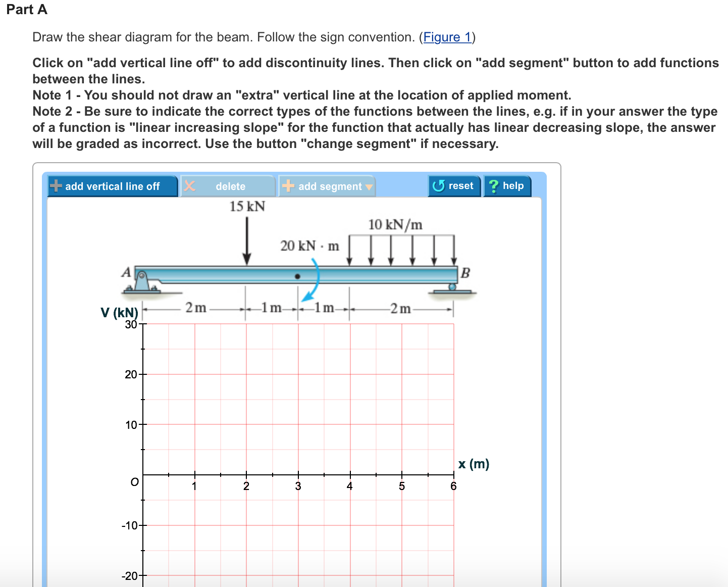
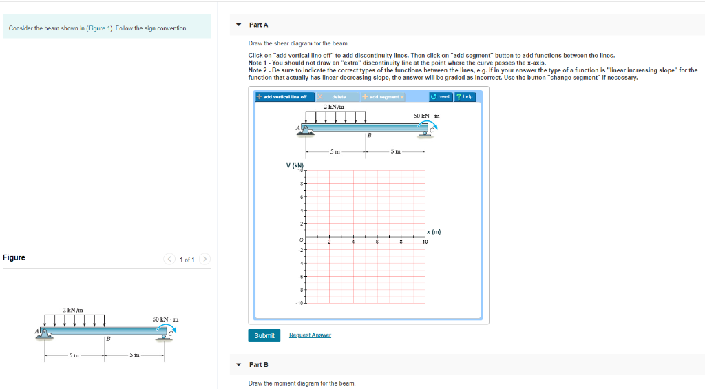
Part A Consider the beam shown in (Figure 1). Follow the sign convention. Draw the shear diagram for the beam Click on "add vertical line off" to add discontinuity lines. Then click on "add segment" button to add functions between the lines. ... Note 2 - Be sure to indicate the correct types of the functions between the lines, e.g. if ...
Solved: PartA Draw The Shear Diagram For The Beam. Follow ...
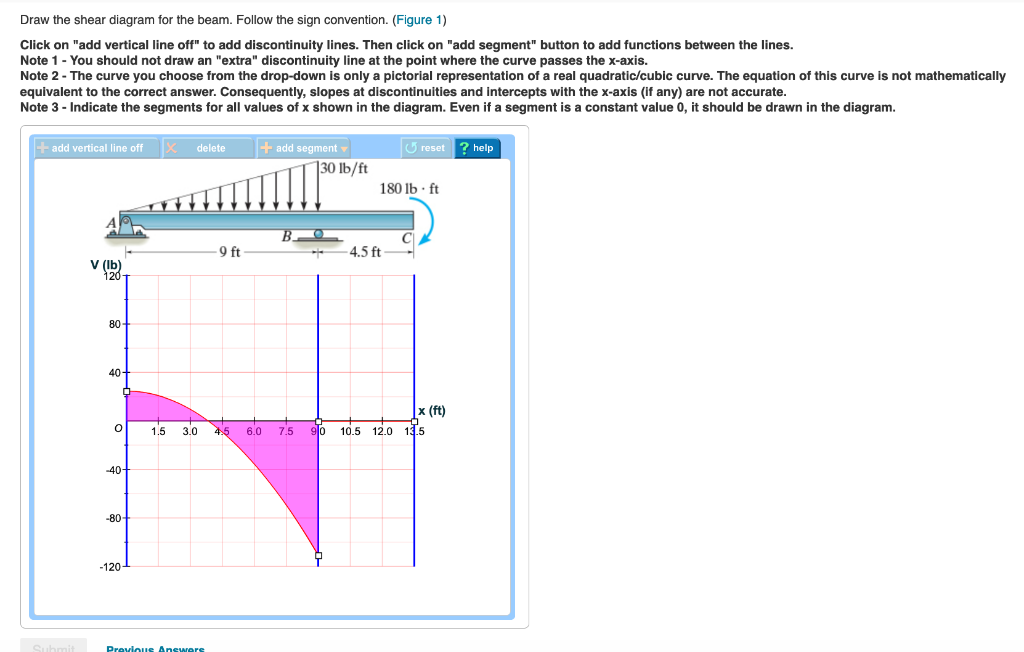
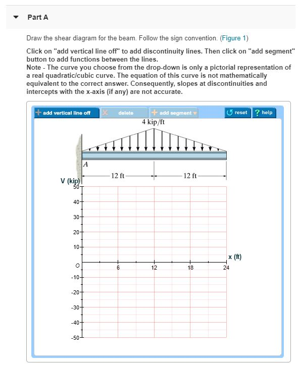
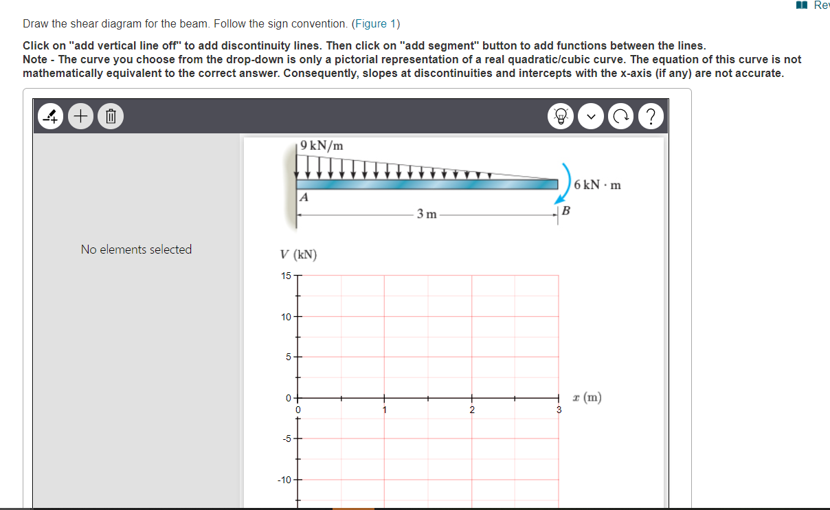
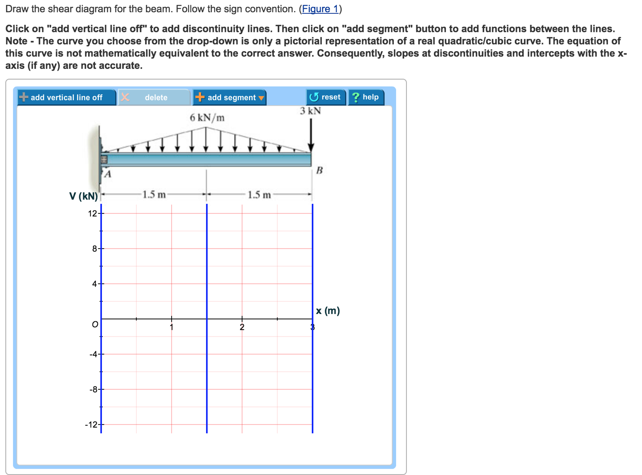
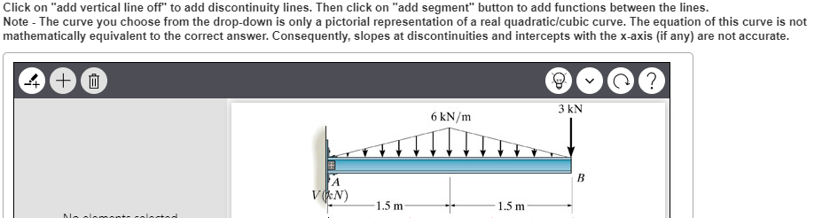
Draw the shear diagram for the beam. Follow the sign convention. (Figure 1) Click on "add vertical line off" to add discontinuity lines. Then click on "add segment" button to add functions between the lines. Note 1 - The curve you choose from the...
Select The Correct Shear Diagram For The Beam Figure 1 ...
Aug 04, 2017 · The three most prominent internal forces in structural analysis calculations are the bending moment, shear force, and axial force. It is very common for people to define and state their sign convention before proceeding with any structural analysis problem. This is mainly due to variations in the selection of positive and negative coordinates.
Res Draw the shear diagram for the beam. Follow the ...
Follow the correct sign convention. B. Draw the moment diagram for the beam. Follow the sign convention. This problem has been solved!
Solved: Part A Draw The Shear Diagram For The Beam. Follow ...
Problem 7.56. Part A. Draw the shear diagram for the beam. Follow the sign convention. (Figure 1). Click on "add vertical line off" to add discontinuity ...
Solved: Part A Draw The Shear Diagram For The Beam. Follow ...
If all the beams have the same orientation,. Staad reports the correct diagram ( following the left up right down shear convention) . When the orientation of the last beam is changed, the start and end point changes, keeping the left up right down SF sign convention, Staad plots this SF diagram .
Solved: Part A Draw The Shear Diagram For The Beam. Follow ...
The following are the important types of beams: 1. Cantilever beam, 2. Simply supported beam, ... We shall remember one easy sign convention, i.e., to the right side of a section, external force ... and B.M. diagrams for the cantilever beam. Shear Force Diagram S.F. at D, F D = + 800 N S.F. at C, F c = + 800 + 500 = + 1300 N
Solved: Draw The Shear Diagram For The Beam. Follow The Si ...
shear force and bending moment and also some basic concepts of strength of materials in our recent posts. We have already seen the various types of beams and different types of loads on beam during our previous posts. Today we will see here the sign conventions for shear force and bending moment diagram in subject of strength of materials with the help of this post.
Solved: Draw The Shear Diagram For The Beam. Follow The Si ...
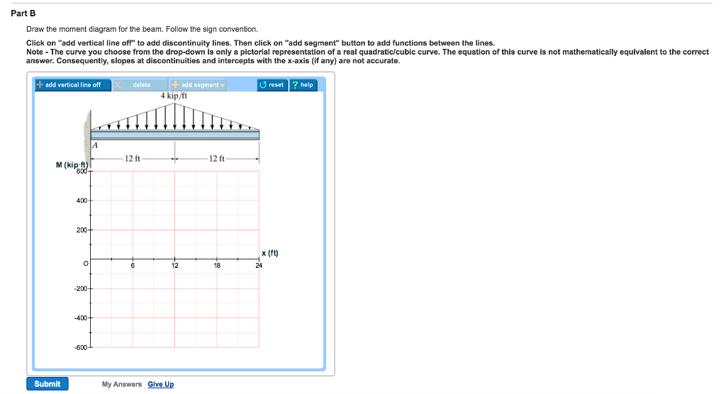
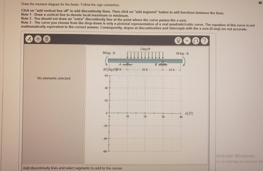
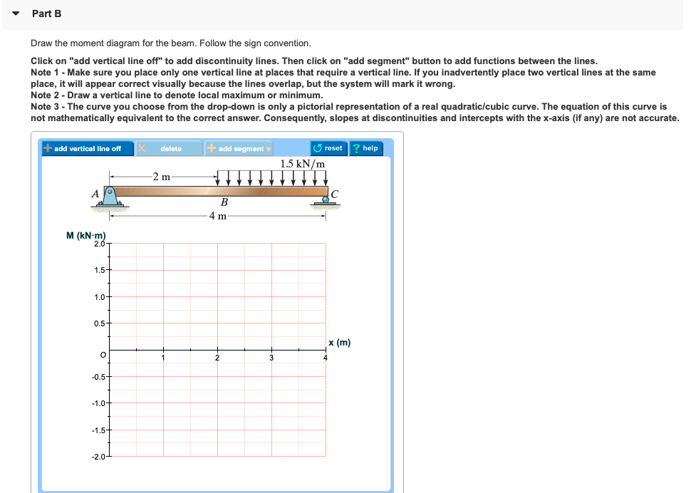
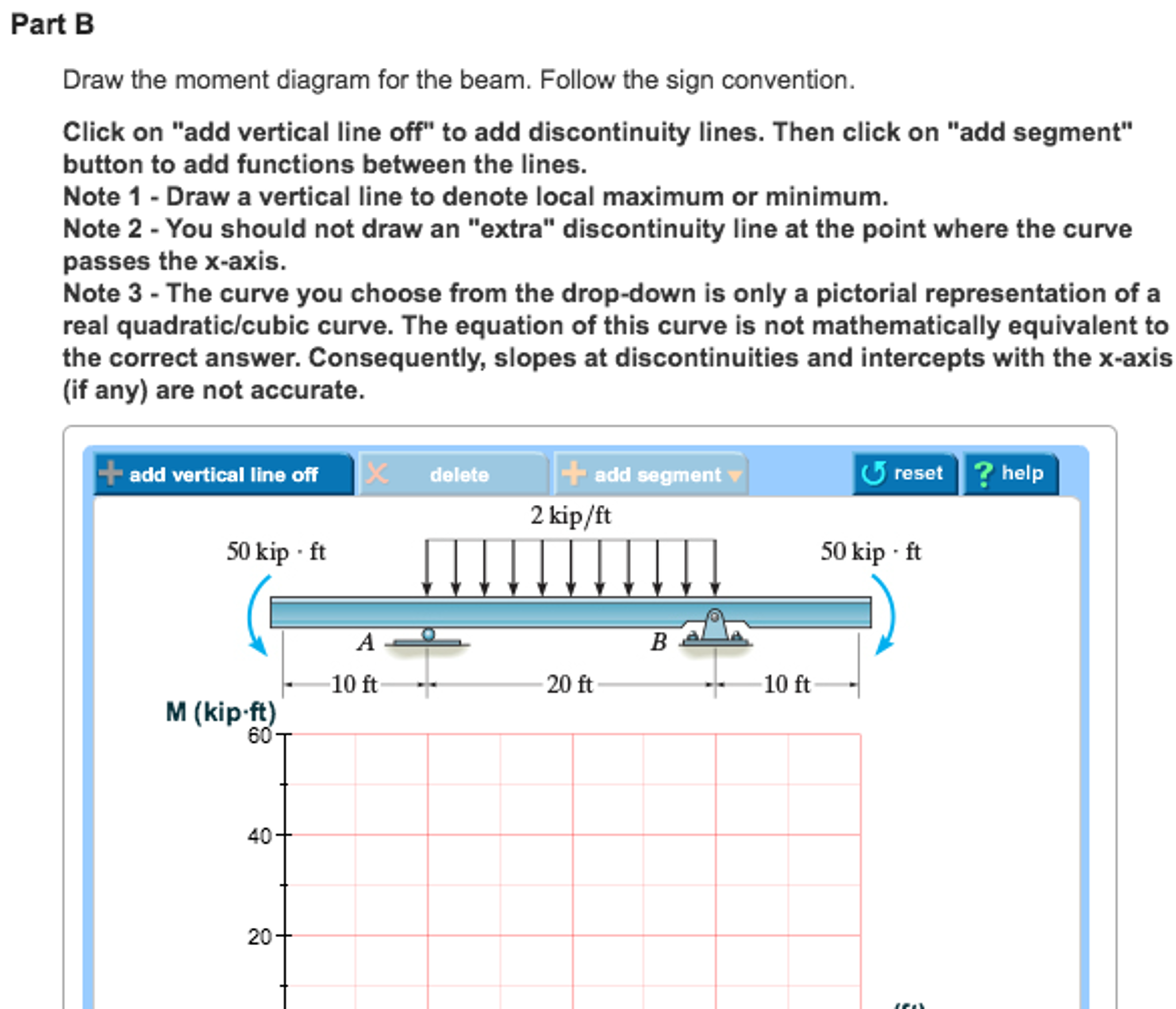
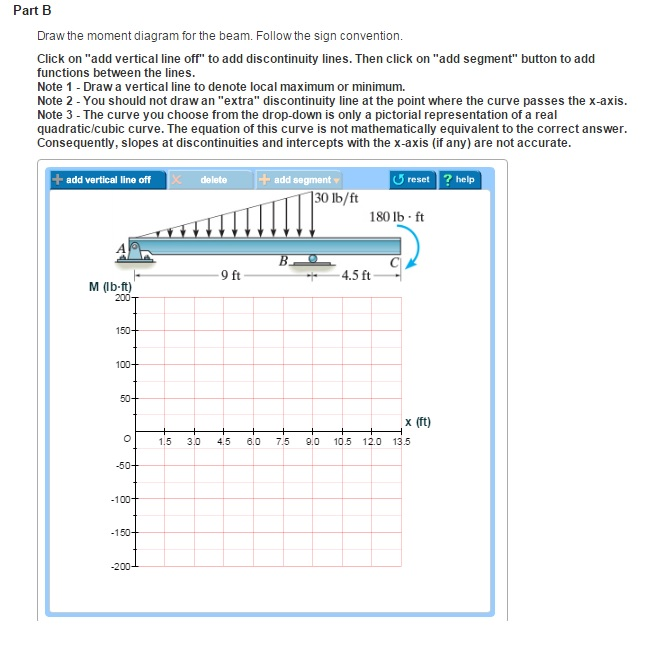
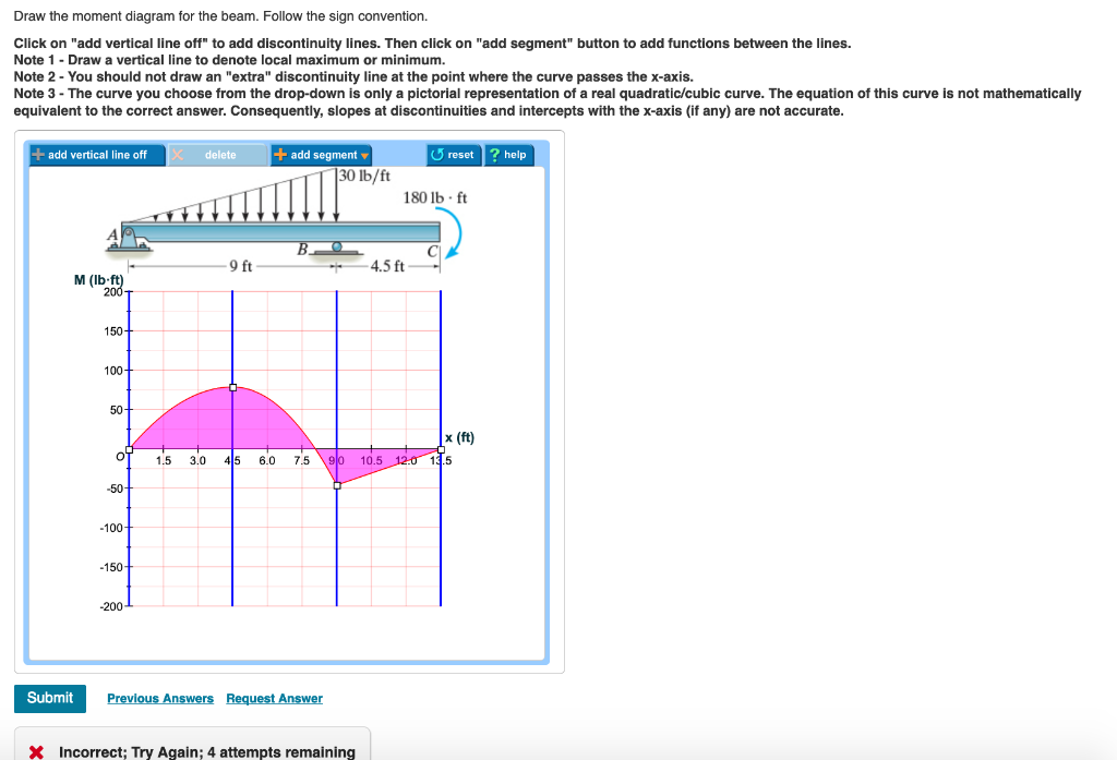
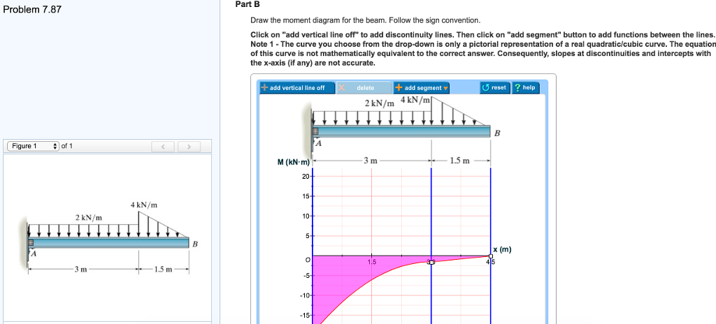
Problem 7.84 Draw the moment diagram for the beam. Follow the sign convention. Click on "add vertical line off" to add discontinuity lines. Then click on "add segment" button to add functions between the lines. Note 1 - Draw a vertical line to denote local maximum or minimum.

Part A Draw the shear diagram for the beam. Follow the ...
Figure (< 1 of 1 > Part A Choose the correct shear diagram for the beam. Follow the sign convention. V = - w6Lx + 3x)/12L V = w(4L - 9x)/12 L 0.444 * V = w(4L2 ...
Solved: Part A Draw The Shear Diagram For The Beam. Follow ...
The shear force will be zero at each end of the beam unless a point force is applied at the end. Construction of bending moment diagram xThe bending moment diagram is obtained by proceeding continuously along the length of beam from the left hand end and summing up the areas of shear force diagrams using proper sign convention.
Solved: Problem 7.66 Consider The Beam Shown In (Figure 1 ...
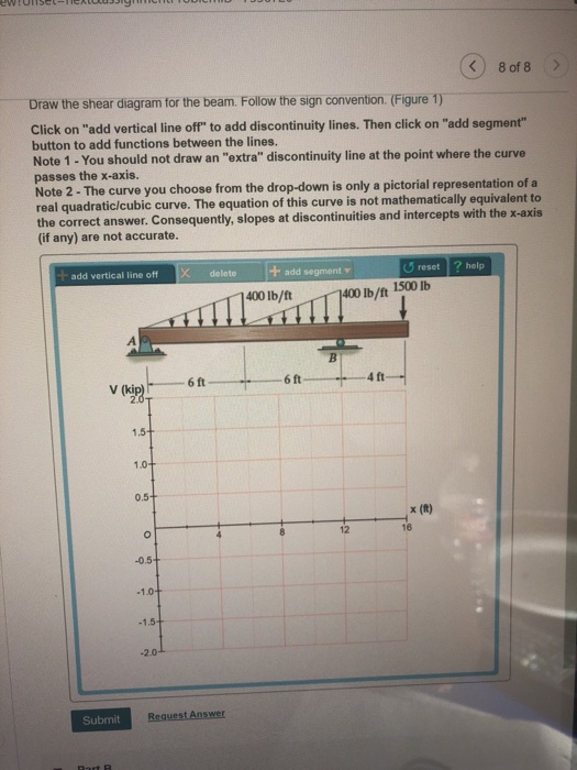
Problem 7.59 Part A Draw the shear diagram for the beam. Follow the sign convention. (Figure 1) Click on 'add vertical line off to add discontinuity lines. Then click on "add segment" button to add functions between the lines. Note 1 - You should not draw an "extra" discontinuity line at the point where the curve passes the x-axis.
Solved: Draw The Shear Diagram For The Beam. Follow The Si ...
Shear and Moment Functions.The beam is sectioned at an arbitrary distance x from the support A,extending within region AB,and the free-body diagram of the left segment is shown in Fig. 6-4b. The unknowns V and M are indicated acting in the positive sense on the right-hand face of the segment according to the established sign convention. Applying
Solved: Part A Draw The Shear Diagram For The Beam. Follow ...
Shear and Bending Moment Diagrams: The loading on most beams is such that the stress resultant on planes perpendicular to the axis of the beam consists of a shear force, V, and a bending moment, M. In determining beam responses, it is very convenient, if not essential, to first determine the shear and bending moment diagrams.
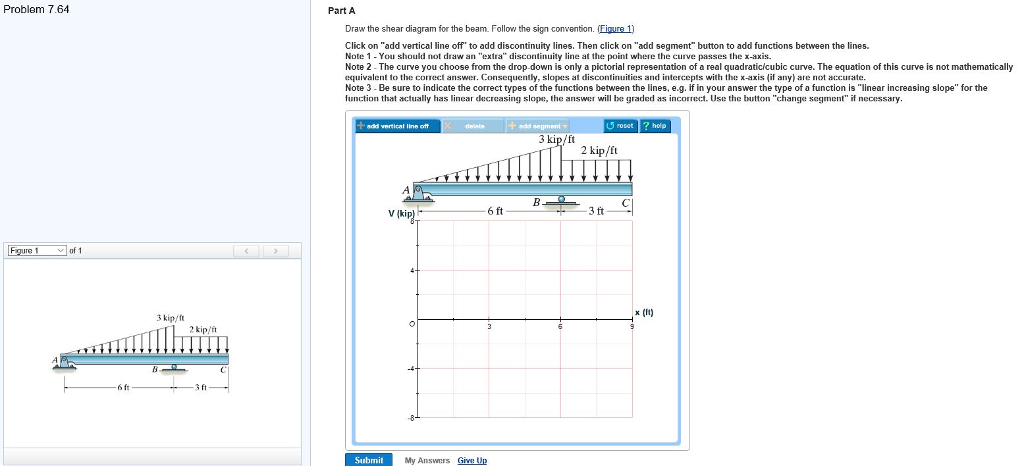
Solved: Problem 7.64 Part A Draw The Shear Diagram For The ...
16.07.2016 · Part A Draw the shear diagram for the beam. Follow the sign convention. (Figure 1) Click on "add vertical line off" to add discontinuity lines. Then click on "add segment" button to add functions between the lines. Note 1 - Draw a vertical line to denote local maximum or minimum. Note 2 - The curve you choose from the drop-down is only a pictorial
Solved: Draw The Shear Diagram For The Beam. Follow The Si ...
For the derivation of the relations among w, V, and M, consider a simply supported beam subjected to a uniformly distributed load throughout its length, as shown in the figure below.Let the shear force and bending moment at a section located at a distance of x from the left support be V and M, respectively, and at a section x + dx be V + dV and M + dM, respectively.
Solved: Draw The Shear Diagram For The Beam. Follow The Si ...
F.1 (b), the positive sign convention is (a) tension axial force, (b) shear forces that produce clockwise momentsand (c) bending moments that result in tension stresses in the interior frame fibers. The sign convention of F.1(b) can be seen to be equivalent to the beam sign convention rotating columns AB and CD to line up with beam BC. 27
Solved: Draw The Moment Diagram For The Beam. Follow The S ...
Solved: Consider The Beam Shown In (Figure 1). Figure

Solved: Part A Draw The Shear Diagram For The Beam. Follow ...
Solved: Which One Is The Right | Chegg.com
PART A Draw the shear diagram for the beam. Follow the ...
Solved: Draw The Shear And Moment Diagrams For This Beam ...
Solved: Review Part A Draw The Shear Diagram For The Beam ...
Solved: Part A Draw The Shear Diagram For The Beam. Follow ...
29 Draw The Shear Diagram For The Beam. Follow The Sign ...
Solved: Draw The Shear Diagram For The Beam. Follow The Si ...

Solved: Problem 7.66 Consider The Beam Shown In (Figure 1 ...
Solved: Part A Consider The Beam Shown In (Figure 1). Foll ...
0 Response to "38 choose the correct shear diagram for the beam. follow the sign convention."
Post a Comment