39 defrost board wiring diagram
Heat Pump Thermostat Wiring Chart Diagram - HVAC - The following graphics are meant as a guide only. Always follow the manufacturer's instructions for both the thermostat and the HVAC system. Additional articles on this site concerning thermostats and wiring can help you solve your problem or correctly wire a new thermostat. Mar 02, 2018 · August 9, 2018. March 2, 2018 by headcontrolsystem. Collection of goodman defrost board wiring diagram. A wiring diagram is a streamlined conventional photographic depiction of an electrical circuit. It shows the elements of the circuit as streamlined forms, as well as the power and also signal links between the devices.
Defrost control board, wiring harnesses, coil and ambient temp sensors, mounting accessories and labels. AUXILIARY HEAT LOCKOUT Above the selected temperature, auxiliary heat will only run during defrost operation. Selectable from 0° to 40°F or off*. COMPRESSOR LOCKOUT Below the selected temperature the compressor does not operate, except in
Defrost board wiring diagram
Oct 04, 2018 · Heat Pump Thermostat Wiring Chart Diagram Quality 101. Air Handler Fan Wont Shut Off Under Repository Circuits 39052 Next Gr. Protech Rheem Ruud Furnace Control Board 62 23599 05. Rheem ruud heat pump defrost control board connecting thermostat on diy wiring question 47 21776 05 oem upgraded 86 diagnosis 62 102635 81 80 2 stage icm318 icm ... Rheem Heat Pump Wiring Diagram - rheem heat pump air handler wiring diagram, rheem heat pump condenser wiring diagram, rheem heat pump defrost board wiring diagram, Every electric structure is made up of various diverse parts. Each component should be set and linked to other parts in specific manner. Otherwise, the arrangement won't function as it should be. wiring diagram ¢710335¥¤ defrost board operation: closes during defrost. rating: 1 a maximum closed when "y" is energized. open when "y" is deenergized. provides "off" delay time of 5 min when "y" is deenergized. with dft closed and "y" energized, compressor run time is accumulated. opening of dft during defrost or interval period resets the interval
Defrost board wiring diagram. Bryant - Carrier Heat Pump Defrost Control Board CESO110063-02. Mode of Operation: Provides a selectable time interval between defrost cycles. It will allow heat for the selected 30/60/90 minute period and provide a 10 minute defrost. A hold input permits the timer to accumulate time only while the compressor is running. Wiring Diagrams January 2012 Using Honeywell Thermostats. ... W1 Out - Output to energize 1st stage heat when in defrost. W2 Out - Output to energize 2nd stage heat when in defrost W1/66 - Used to energize 1st stage heat when in defrost ... X/L can be eliminated as the fault codes can be retrived from the board. 47-102684-83 Rheem Ruud Heat Pump Defrost Control Board. $ 65.00 $ 60.00. The 47-102684-83 Rheem Ruud heat pump defrost control board is brand new and comes in an anti-stat bag, packed in a Genuine OEM Protech factory parts box. The 47-102684-83 heat pump defrost control is used on many Rheem, Ruud heat pumps. The defrost control board in the condenser will automatically defrost the system. When it goes into defrost mode, the backup heat is energized. In most cases, if you are changing your thermostat, you do not have to worry about any wiring at the condenser. Auxiliary Thermostat Wiring for Heat Pump Thermostats | How to Wire a Heat Pump for Control
Goodman B12260 08 Wiring Diagram Pump Defrost Board Wiring Diagram On Heat Pump Defrost Wiring Goodman B12260 08 Wiring Diagram - wiring diagram is a simplified adequate pictorial representation of an electrical circuit. It shows the components of the circuit as simplified shapes, and the skill and signal connections in the middle of the devices. Refer to the wiring diagram and wiring table when connecting the 47D40-801 control to other components of the system. UL approved, 105o C rated 18 gauge min., stranded 2/64" thick insulation wire is recommended for all low voltage safety circuit connections. UL approved, 105o C rated 16 gauge min., stranded 2/64" http://tandnservices.com 770-490-5595 T&N Services LLC. proudly provides HVAC services to the North Georgia area including:Atlanta, Canton, Woodstock, Mariet... CIRCUIT BOARD DEFROST THERMOSTAT DEFROST RELAY AND CIRCUITRY DISCHARGE TEMP. SWITCH HIGH PRESSURE SWITCH LOW PRESSURE SWITCH ... CONNECTION DIAGRAM SCHEMATIC DIAGRAM (LADDER FORM) Wiring Diagram Split System Heat Pump PH13 Sizes 018—060 Form: WD-PH13-01 Cancels: New Printed in U.S.A. 4-05 Catalog No. WD-PH13-01.
May 16, 2018 · May 16, 2018 by faceitsalon. Assortment of goodman defrost board wiring diagram it is possible to download free of charge. Please download these goodman defrost board wiring diagram by using the download button, or right click selected image, then use Save Image menu. Wiring diagrams help technicians to view how the controls are wired to the system. WIRING DIAGRAM 1 2 3 4 Closing during defrost. Rating: 1 Amp. Max. Op e nsdu r i gf o t .R a: 2HP 30 V c M x Closed when "Y" is Fon. Open when "Y" is off. Provides "off" delay time of 5 min. when "Y" opens. With DFT closed and "Y" closed, compressor run time is accumulated. Opening of DFT during defrost or interval period resets the interval to 0. 2 Some systems perform a defrost cycle based on elapsed time. A time is chosen as an interval between defrosts. Whenever the timer counts up the chosen amount of time, the system enters a Fig. 7. Wiring diagram for systems with pressure switches in series with the contactor and no connection to the defrost control. Fig. 8. Wiring diagram for simple timer applications. CONFIGURATION 1. Connect power. 2. On power up the display will briefly flash the soft-ware version of the DB7110U and then begin cycling between the normal ...
The Sequence of Operation for a Defrost Heat Pump Board ...
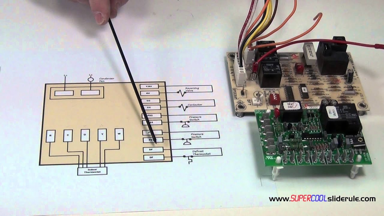
In this HVAC video, I go over how the Heat pump defrosts control board works, how to wire each terminal on the board, what happens during defrost mode, the v...

Freezer Defrost Timer Wiring Diagram #2 | Circuit diagram ...
Tempstar Hvac Age Manuals Parts Lists Wiring Diagrams Pdf S Contact Info. 10 Kw Heat Strip For Tempstar Package Units Pa Ph Wgs1002. Heat Pump Thermostat Wiring Diagram. Wire A Thermostat. 1087562 Icp Heil Tempstar Heat Pump Defrost Control Board. I Have A Tempstar 2200 Heat Pump Returned Home Yesterday And Found System Off Thermostat Had 70 ...
![[XD_1803] Wiring Diagram Also Heat Pump Defrost Circuit ...](https://static-cdn.imageservice.cloud/14415308/46-goodman-furnace-control-board-troubleshooting-pcbbf118s-furnace.jpg)
[XD_1803] Wiring Diagram Also Heat Pump Defrost Circuit ...
When a defrost cycle is initiated, defrost board turns off the outdoor fan. The defrost board supplies 24 Volts AC to "O" and "W2". The reversing valve is energized and turns on the electric heater(s). The unit will continue to run in this mode until the defrost cycle is completed.

Bryant Defrost Circuit Board Wiring Diagram - Wiring ...
Goodman Wiring Diagram Pcbdm133. LII ICM DEFROST CONTROL. Replaces: Direct replacement for Goodman PCBDM WIRING DIAGRAM. Compressor Run Times. Defrost Times. wiringall.com: Goodman PCBDMS Defrost Control Board Appliance so you can compare the wiring diagrams for the old and new defrost control boards. 25HCB3.

ICP Heil Tempstar Heat Pump Defrost Control Circuit Board ...
Oct 22, 2018 · Icm318 Icm Heat Pump Defrost Control For Goodman B1226008 Controls Com. Rheem ruud heat pump defrost control board connecting thermostat on wiring question diy 47 21776 86 05 oem upgraded diagnosis 102685 02 carrier 62 102635 81 80 2 stage white rodgers 30 volt problem doityourself icm318 icm controls emerson universal amana circuit new direct factory replacement diagram condenser fan motor 51 ...

47-21776-86 Rheem Ruud Heat Pump Defrost Control Board
Control wiring 5 Mechanical cooling sequence of operation 11 Heating control (Electric heat, Modulating heat control, Hydronic Heat First) 17 Heat pump control (Independent defrost, Dual fuel) 22 Operation with a conventional thermostat 23 Test modes 27 Alarm relay 34 Troubleshooting 35 LCI-R LonTalk® Communication Interface 42

A morning yoga session peering into the jungle in Ubud, Bali.
Goodman Wiring Diagram Pcbdm133. All parts are inspected for signs of installation upon our receipt of them. This is OEM Goodman Amana Janitrol Heat Pump Defrost Control Board PCBDM schematron.org: Goodman PCBDMS Defrost Control Board Appliance so you can compare the wiring diagrams for the old and new defrost control boards.

1016567R Nortek Nordyne Defrost Control Board Factory OEM ...
Circuit Board - PCBDM133S / PCBDM160S Defrost Control Board The PCBDM133S control board is a guaranteed genuine Goodman OEM replacement for several Goodman, Amana, and Janitrol units. All of our parts are shipped factory direct, giving you the assurance you need for a quality repair on your furnace, air conditioner, or other Goodman product.

Hvac Control Board Wiring Diagram : Goodman Defrost Board ...
I have a Trane heat pump with a CNT01923 defrost control board that is not working. I ordered an upgraded board CNT05001 that replaces CNT01923. The board did not come with any upgrade instructions or wiring diagram and the board connector are different than those on CNT01923.

Wiring Control Board | Wiring Diagram Database
Need a wiring diagram for a Nordyne 624644 defrost board - Answered by a verified HVAC Technician We use cookies to give you the best possible experience on our website. By continuing to use this site you consent to the use of cookies on your device as described in our cookie policy unless you have disabled them.

SOLVED: Maytag MZD2665HEW ADC replacement - Fixya
Jun 11, 2020 · Defrost Control Board Wiring Diagram – wiring diagram is a simplified welcome pictorial representation of an electrical circuit. It shows the components of the circuit as simplified shapes, and the facility and signal connections in the middle of the devices.

FIXED - Need schematic for defrost control board in ...
wiring diagram ¢710335¥¤ defrost board operation: closes during defrost. rating: 1 a maximum closed when "y" is energized. open when "y" is deenergized. provides "off" delay time of 5 min when "y" is deenergized. with dft closed and "y" energized, compressor run time is accumulated. opening of dft during defrost or interval period resets the interval
HVAC Service- Trane XR12 Defrost Failure - YouTube
Rheem Heat Pump Wiring Diagram - rheem heat pump air handler wiring diagram, rheem heat pump condenser wiring diagram, rheem heat pump defrost board wiring diagram, Every electric structure is made up of various diverse parts. Each component should be set and linked to other parts in specific manner. Otherwise, the arrangement won't function as it should be.

Goodman Control Board B18099-23 Instructions
Oct 04, 2018 · Heat Pump Thermostat Wiring Chart Diagram Quality 101. Air Handler Fan Wont Shut Off Under Repository Circuits 39052 Next Gr. Protech Rheem Ruud Furnace Control Board 62 23599 05. Rheem ruud heat pump defrost control board connecting thermostat on diy wiring question 47 21776 05 oem upgraded 86 diagnosis 62 102635 81 80 2 stage icm318 icm ...

OEM ICP Heil Tempstar Sears Defrost Control Circuit Board ...

Need wiring diagram for lennox 84W88 installation. System ...
![[DIAGRAM] Goodman Heat Pump Defrost Control Board Wiring ...](https://i.ebayimg.com/images/g/aYwAAOSwpDdVCZlR/s-l640.jpg)
[DIAGRAM] Goodman Heat Pump Defrost Control Board Wiring ...

I have a York heat pump and my defrost board was bad. I ...

Defrost Board Wiring Diagram - kapris-naehwelt

HVAC Heat Pumps 2 - YouTube

Person holding skateboard
Goodman Defrost Board Wiring Diagram - AQDANOREO

Do Something Great

Ranco Defrost Board Wiring Diagram - commonsensicalkyrie

Wiring Diagram Heat Pump Defrost Board ...
![[DIAGRAM] Goodman Heat Pump Defrost Control Board Wiring ...](https://f01.justanswer.com/JACUSTOMER2dihsg89/2015-02-24_123853_defrost_wiring001.jpg)
[DIAGRAM] Goodman Heat Pump Defrost Control Board Wiring ...
![[XD_1803] Wiring Diagram Also Heat Pump Defrost Circuit ...](https://static-resources.imageservice.cloud/6936569/heat-pump-manual-defrost.jpg)
[XD_1803] Wiring Diagram Also Heat Pump Defrost Circuit ...

Goodman Heat Pump Defrost Board Wiring Diagram - WIRGRAM
![[XD_1803] Wiring Diagram Also Heat Pump Defrost Circuit ...](https://static-resources.imageservice.cloud/12462969/rheem-heat-pump-diagram-wiring-diagram-database.jpg)
[XD_1803] Wiring Diagram Also Heat Pump Defrost Circuit ...
Heat Pump new: Heat Pump Defrost Board
ICM319 Defrost Control Circuit Board Nordyne 624519A ...

Goodman Defrost Board Wiring Diagram - AQDANOREO
![[DIAGRAM] Icp Heat Pump Defrost Board Wiring Diagram For ...](https://usermanual.wiki/LENNOX/L0806654.1603647104-User-Guide-Page-9.png)
[DIAGRAM] Icp Heat Pump Defrost Board Wiring Diagram For ...
Coleman Gas Furnace Control Circuit Board 031-01910-000 ...
![[HX_9839] York Luxaire Coleman Honeywell Heat Pump Defrost ...](https://static-resources.imageservice.cloud/16205586/hvac-defrost-wiring-connection-diagram-online-wiring-diagram.jpg)
[HX_9839] York Luxaire Coleman Honeywell Heat Pump Defrost ...
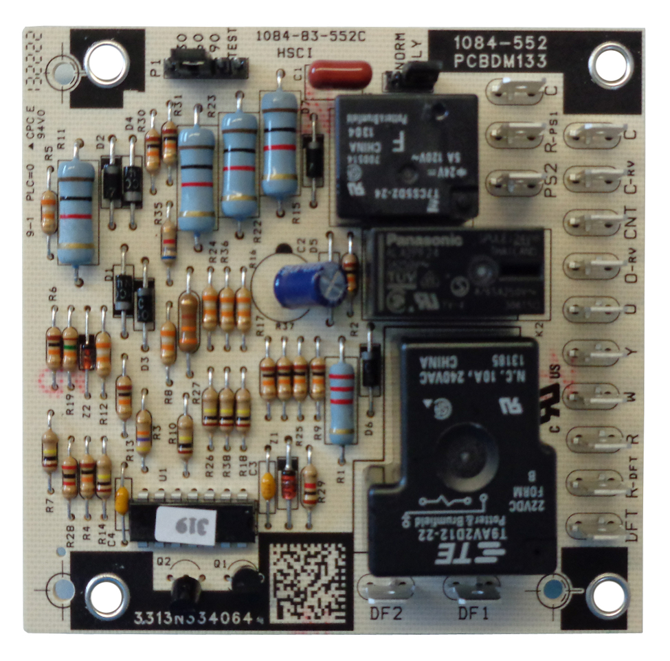
Circuit Board - PCBDM133S / PCBDM160S Defrost Control ...

Goodman Pcbfm103s Wiring Diagram

Defrost Control Board Heat Pump Wiring / Defrost ...
Bryant - Carrier Heat Pump Defrost Control Board CESO110063-02
0 Response to "39 defrost board wiring diagram"
Post a Comment