39 hunter src wiring diagram
Open hinged wiring compartment door to access the terminal strip area shown in the diagram. 5. Route the valve wires through the large opening on the base ...32 pages Hunter Src Wiring Diagram The SRC was Hunter's entry-level residential controller that stopped shipping in 2011. The SRC was replaced by the PCC, a fixed-station, cost effective upgrade developed to offer the homeowner a more efficient and versatile controller solution.
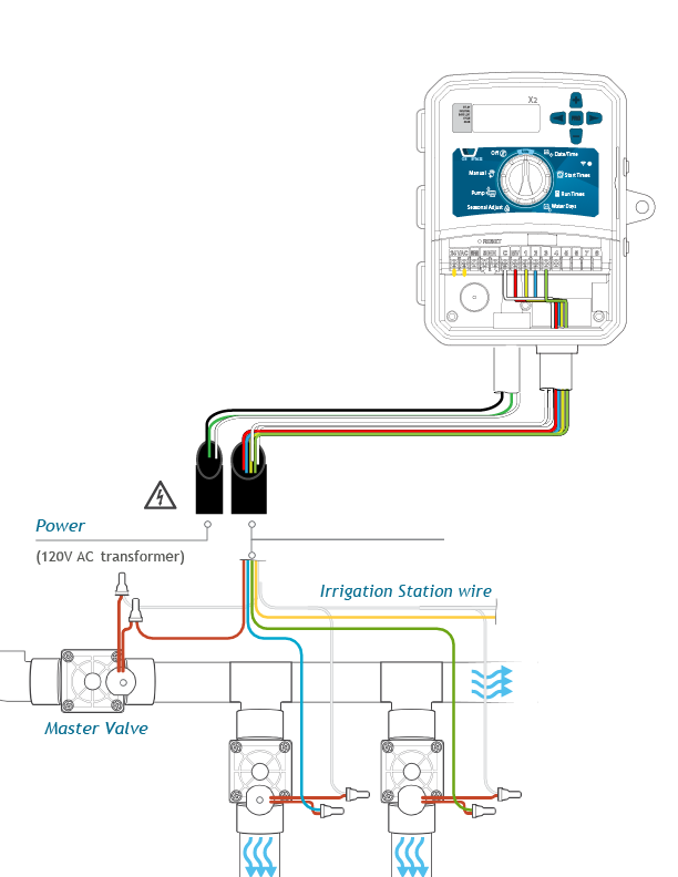
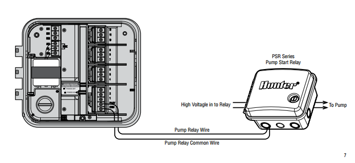
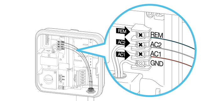
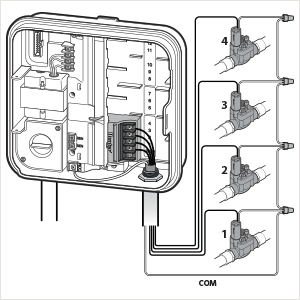
Below is a typical drawing and description of a Hunter SRC series timer Master/Pump valve wiring. Most sprinkler timers will be similar to this example. Route wires from the master valve or pump start relay location into the controller with the valve wires. Connect either wire from the pump relay to the MV terminal.
Hunter src wiring diagram
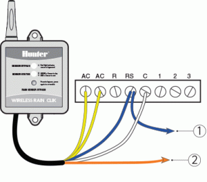
SRC Plus Controller Has Been Replaced By PCC The SRC was Hunter's entry-level residential controller that stopped shipping in 2011. The SRC was replaced by the PCC, a fixed-station, cost effective upgrade developed to offer the homeowner a more efficient and versatile controller solution. SRC owners in search of a new controller are urged to consider either the PCC, or X-Core with Solar Sync ... Attach the two yellow wires to the AC terminals of the SRC (polarity does not matter). Attach the blue wire to the RS terminal. Attach the white wire to the "C" terminal. Attach the valve common wire to the RS terminal. Reference Illustration Common wire to all valves Used for normally open sensor applications. 20 1955 Chevy Ignition Switch Wiring Diagram; 26 Consider The Following Reaction Energy Diagram; 25 John Deere L130 Belt Diagram; 27 Hunter Src Wiring Diagram; 32 Open Range Rv Wiring Diagram; 35 Gsg 1911 22 Parts Diagram; 28 John Deere 111 Belt Diagram; 29 Catalina 22 Rigging Diagram; 33 Light Ray Diagram; 23 Dual Xdm16bt Wiring Diagram
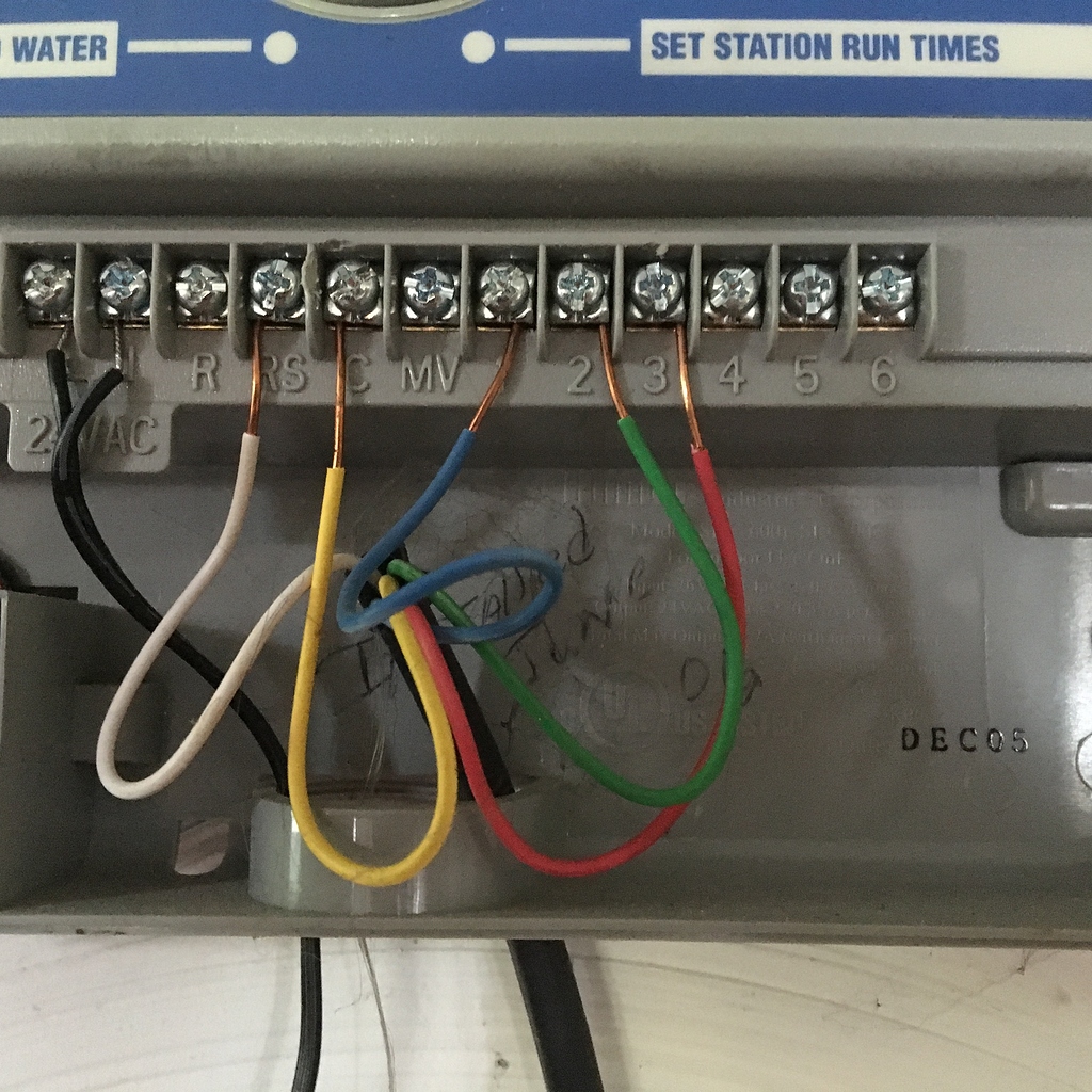
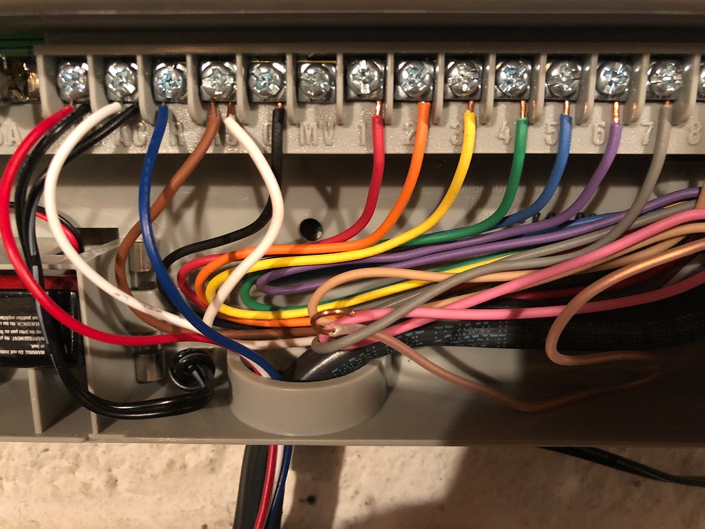
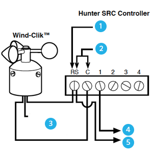
Hunter src wiring diagram. WIRING DIAGRAM 1: HUNTER SRC, SRC PLUS. A. C. A. C. M. V. CR. S. R. SRC. Rain Sensor. Power. Supply. To Valves. SRC (Plus). SerialBrick -. Hunter Industries is pleased to present the SRC – a Simple and Reliable Controller for residential applications. Designed with . Route control wires between control valve location and controller. Typically it is area shown in the diagram. 5. Hunter ... May 26, 2018 · Hunter SRC Plus wiring. Moving over to a Rachio 2nd gen. On the current Hunter SRC Plus, there are two wires connected to the RS terminal. Where do these go on the new controller? I tried connecting the white to SC and black to S1 No luck The Hunter controller requires... 5.9 Cummins Injector Wiring Diagram; Kicker Compr 12 Dvc 2 Ohm Wiring Diagram; 1977 Hodaka Wiring Diagram; Hunter Src Wiring Diagram; Snapper Riding Lawn Mower Wiring Diagram; Sony Xav-701hd Wiring Diagram; Cva Optima Trigger Assembly Diagram; Drive Medical Sfscout3 Wiring Diagram; Kenwood Kdc-bt562u Wiring Diagram; Dano Bass Wiring Diagram ... Wiring to the Hunter SRC The Mini-Clik connects directly to the SRC. This allows you to easily override the sensor by using the RUN (BYPASS SENSOR) position on the dial. 1. Route the wires from the Mini-Clik up through the same opening used for valve wiring. 2. Connect one wire to the RS terminal and other to the C terminal (See Figure 1). 3.
STEP 3: Check Sensor and Sensor Wiring Remove one sensor wire from one of the SEN terminals. If the controller displays SEN OFF, a problem exists with the sensor and/or sensor wiring. Common problems with sensor wiring include: 1) staples through wire insulation, 2) poor wire splices, 3) metal contacting sensor wires through cut in the insulation. Hunter Industries is pleased to present the SRC – a Simple and Reliable Controller for residential applications. Designed with the needs of the customer in mind, the SRC offers simplified dial programming and an impressive range of features typically found in controllers costing twice . as much. While it’s affordable, the SRC is without a doubt a professional grade product. The controller ... Kia Picanto Radio Wiring Diagram; Hunter Src Wiring Diagram; 2013 Gmc Sierra Denali 3500hd Ome Rear View Camera Plug Wiring Diagram; Csst Bonding Diagram; Engine Compartment Wiring Diagram For 1967 Buick Skylark; 72 Ct90 Wiring Diagram; Offensive Football Formations Diagrams; Bachmann Ho Mogul 2-6-0 Wiring Diagram; H&h Trailer Wiring Diagram ... 4. Open hinged wiring compartment door to access the terminal strip area shown in the diagram. 5. Route the valve wires through the large opening on the base of the cabinet or through ½ inch conduit if installed. Strip ¼ inch of insulation from ends of all wires. 6. Secure the white valve common wire to the screw on the terminal marked C ...
A wiring diagram is a streamlined standard pictorial representation of an electrical circuit. Collection of sprinkler system wiring diagram. Water flow is measured in gallons per minute. Wiring a sprinkler system controller is fairly straightforward and involves matching your system s wires to the correct terminals. Open hinged wiring compartment door to access the terminal strip area shown in the diagram. 5. Route the valve wires through the large opening on the base of ...32 pages Volvo Penta wiring diagram (2003) (460 Kb) uploaded by Weather for Mariners (4,858 Kb) uploaded by JamesG161 WEMA guide for troubleshooting tank senders (4,743 Kb) uploaded by Anam_C West System - Gelcoat-Blister-Diagnosis-Repair and Prevention (2,426 Kb) uploaded by Crusty Ol Salt Westerbeke 4-107 (1,190 Kb) uploaded by nheinlein Open hinged wiring compartment door to access the terminal strip area shown in the diagram. 5. Route the valve wires through the large opening on the base of ...32 pages
Nutribullet Parts Diagram. For a complete list of available NutriBullet accessories, visit The unique combination of the Extractor Blade and our exclusive Cyclonic Action generate the. Nutribullet now recommends that users should not mess with the gaskets and should just buy a new blade assembly (The manual recommend.
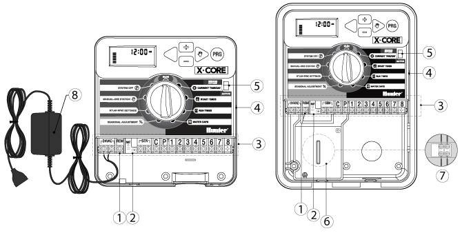
Designed with the . Terminal Strip Area - Use to attach transformer and valve wires from area shown in the diagram. 5.Below is a typical drawing and description of a Hunter SRC series timer Master/Pump valve wiring. Hunter Src Wiring Diagram Hunter Irrigation Controllers / Timers: MANUAL JUMP MENU.
Hunter SRC 9 Station Indoor Mount Controller. Features and Benefits. Dial programming Easy program entry for installers and end-users. 3 programs with multiple start times
Hunter.Irrigation.Management.and.Monitoring.System™.(Not.Included). ... The.controller's.large.cabinet.provides.ample.room.for.wiring. ... SRC.to.the.44 pages
Hunter Src Wiring Diagram The SRC was Hunter's entry-level residential controller that stopped shipping in 2011. The SRC was replaced by the PCC, a fixed-station, cost effective upgrade developed to offer the homeowner a more efficient and versatile controller solution. SRC / SRC Plus | Hunter Industries SRC Controllers are no longer available ...
Acces PDF Hunter Sprinkler Controller Manual Src Indoor Model (International) MPC. Optional Outdoor Cabinet. SRC ® NOW WITH . NON-VOLATILE MEMORY Hunter SRC User Manual | 32 pages View and Download Hunter SRC instructions online. SRC controller pdf manual download. Also for: Src plus, Ec, Xc, X-core, Pro-c, Pcc, Icc, Svc, Node, Page 5/27
Wiring Wizard SURE to do a big 3 upgrade to your electrical system along with standard wiring. Make sure your wires are all OFC and connections are tight. Rockford Fosgate RMD2B • W 10" Prime R1 Series Dual 2-Ohm lead wire • Linear high excursion matched motor magnetics and suspension design. All Support Tools.
Hunter SRC. The Mini-Clik connects directly to the SRC. ... With the two wires from the Mini-Clik at the controller, locate the “common wire" of the ...
Residential/Light Commercial. Irrigation Controller. Owner's Manual and. Programming Instructions.. 600i. 6-station Indoor Model.
Hunter Src Wiring Diagram The SRC was Hunter's entry-level residential controller that stopped shipping in 2011. The SRC was replaced by the PCC, a fixed-station, cost effective Page 28/46. Read PDF Hunter Sprinkler Controller Manual Src upgrade developed to offer the homeowner a more efficient and versatile controller solution.
Hunter Src Wiring Diagram - diagramweb.net Owner's Manuals and Instruction Sheets Easy-to-understand owner's manuals and instruction sheets make installing and programming Hunter products a simple task. Our manuals contain clear illustrations, easy to read fonts, and are written by the engineers and product managers that brought the products to ...
Step by step instructions for programming a Hunter SRC Plus sprinkler timer/controller. Tips for when and how long to water.Please support my YouTube channel...
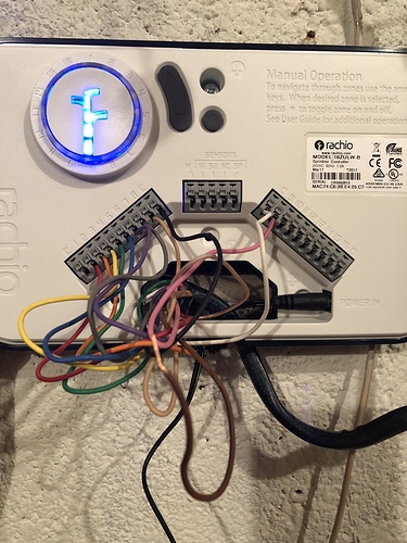
Hunter SRC Complex Wiring. DLane September 15, 2017, 3:38pm #2. @Justonma - without looking at the wire bundle heading out to the valves and going default wire colors, I'd move the white wire to a Rachio C (ommon) port. If it is desired to include the rain sensor in the Rachio configuration then I'd put the gray wire in the Rachio SC ...
Hunter Src Plus Wiring Diagram Source: www.hunterindustries.com READ Oxygen Sensor Wiring Diagram Ford Database Read cabling diagrams from negative to positive in addition to redraw the signal like a straight line.
Wiring. SRC Controller: (See Figure 2). Attach the two yellow wires to the AC terminals of the SRC (polarity does not matter) ...
Before wiring your Rain-Clik, it is important to select an appropriate mounting location for the transmitter. Click here to view mounting instructions for the Rain-Click transmitter. Once the Rain-Clik is mounted, run the wire to the controller, and fasten it every few feet with wire clips or staples for best results. If an extension to the wire provided is needed, use the following table to ...
Np205 Diagram. Retainer, Input bearing Gasket, Input retainer Bearing and snap ring, Input Ring, Retainer Input brg. Pin, Thrust. Tips and tricks for the toughest transfer case available, the bulletproof NP Does any body know where I can find a diagram for a NP I just took the one out of my truck and picked up another one that I want to.
Dec 11, 2017 · Controller Wiring Guide Irrigation Express. Pro c connecting station wires x core connecter une électrovanne troubleshooting electrical issues in how to wire rs terminal from hunter src hcc power module wiring diagram hc solenoid valves and ac x2 a master valve plus 2 by dlane sprinkler pump industries rachio 3 clik irrigation systems new install replacing on controller guide gen unit working ...
Hunter Industries X2 800 Wiring Diagram Page 1. Oem Hunter Ceiling Fan Wire Harness K226601h03 Ships Today Fix Com. Hunter Fan Company 27182 Wall Control User Manual Manualzz. Hunter Src Plus Wiring 2 By Dlane Rachio Community. Hunter Fan Company.
Wiring to the Hunter SRC The Mini-Clik connects directly to the SRC. Wiring diagram for hunter sprinkler system. Hunter Sprinkler System Wiring Diagram Author. How to connect hunter x core master pro c connecting station wires hcc power module wiring diagram hc solenoid valves and ac controller guide irrigation plug pack src plus 2 by dlane wire rs terminal from x2 a valve rain bird sensor ...
Hunter Src Wiring Diagram Database. Electrical cabling is a potentially harmful task if completed improperly. One need to never attempt operating on electrical electrical wiring without knowing the below tips as well as tricks followed by even the the majority of experienced electrician.
It also has circuitry to translate logic level signals to the Hunter remote bus. On top of the board are three pins so it can plug directly into the Hunter SmartPort. There are also terminal blocks in case you want to wire it directly to the control panel without the SmartPort. I mounted the Sprinkler Shield on an Esquilo Air.
For use with Hunter Controllers with SmartPort® Connection ... WIRING THE SMARTPORT® TO HUNTER CONTROLLERS . ... SRC Controller SmartPort® Installation.30 pages
20 1955 Chevy Ignition Switch Wiring Diagram; 26 Consider The Following Reaction Energy Diagram; 25 John Deere L130 Belt Diagram; 27 Hunter Src Wiring Diagram; 32 Open Range Rv Wiring Diagram; 35 Gsg 1911 22 Parts Diagram; 28 John Deere 111 Belt Diagram; 29 Catalina 22 Rigging Diagram; 33 Light Ray Diagram; 23 Dual Xdm16bt Wiring Diagram
Attach the two yellow wires to the AC terminals of the SRC (polarity does not matter). Attach the blue wire to the RS terminal. Attach the white wire to the "C" terminal. Attach the valve common wire to the RS terminal. Reference Illustration Common wire to all valves Used for normally open sensor applications.
SRC Plus Controller Has Been Replaced By PCC The SRC was Hunter's entry-level residential controller that stopped shipping in 2011. The SRC was replaced by the PCC, a fixed-station, cost effective upgrade developed to offer the homeowner a more efficient and versatile controller solution. SRC owners in search of a new controller are urged to consider either the PCC, or X-Core with Solar Sync ...












0 Response to "39 hunter src wiring diagram"
Post a Comment