39 unity feedback block diagram
Oct 07, 2021 · Learn the feedback loop definition. See a feedback loop diagram and feedback loop examples to get a clear understanding of the concept and how it can be applied to business organization, biology ... 29.10.2020 · An oscillator is a mechanical or electrical construction that produces oscillation based on some variables. This oscillator is used from clock to various metal detectors and even on computers where microprocessors and microcontrollers exist The oscillator in which the RC circuit is used as a feedback path is the RC phase shift oscillator. It generates stable sine …
Download scientific diagram | Block diagram of the unity feedback control systems. from publication: Characterization of the Stabilizing PID Controller Region for the Model-Free Time-Delay System ...

Unity feedback block diagram
A unity feedback system is a control system that has no component in the feedback path . If W = V = 0: General case: Categories. Categories. Information processing structures. Block Diagram Simplification –Example 1 Rearrange the following into a unity‐feedback system Move the feedback block, * O, forward, past the summing junction Add an inverse block on 4 Oto compensate for the move Closed‐loop transfer function: 6 O L 1 * O * O ) O 1 O * O L ) O 1 O * O K. Webb MAE 4421 16 Problem 30. A unity-feedback system is shown in the block diagram below: K(s + ! ) s(s + 1)(s + 10) a. Find so the system will have a settling time of 4 seconds for large values of K. The expression for 2% settling time Ts is Ts = 4 !n = 4 sec =) !n = 1; (10) where !n is the REAL part of a complex pole location. The closed-loop TF is C(s) R(s ...
Unity feedback block diagram. Problem 15. The block diagram for this problem is shown below in Figure 3: Since the system TYPE is the number of \free" integrations in the forward path, we need to reduce the system block diagram to the point where we have the forward path transfer function. First reduce the inner loop, G(s) inner = 100(s+ 2) s(s+ 5) + 1000(s+ 2) = 100(s+ 2 ... Must have unity feedback to use Table 7.2! Problem #38 in Unity Gain Form + C(s)-R(s) 2) 1 + + + - s K-1 What is G(s) in the unity feedback form? + C(s)-R(s) E(s) 2 ( 1)( 1) 1 3 + 2 + − + + s s K s s Type 0! Solve Problem #38 Since we have a Type 0 system, 1 1 lim ( ) 0 − = = → K K G s s p 1 1 1 1 1 1 1 1 1 100 0.1 0.1% − + − = − ... The symbol used to represent a summing point in closed-loop systems block-diagram is that of a circle with two crossed lines as shown. The summing point can either add signals together in which a Plus ( + ) symbol is used showing the device to be a "summer" (used for positive feedback), or it can subtract signals from each other in which case a Minus ( − ) symbol is used showing that the ... 158 BLOCK DIAGRAM ALGEBRA AND TRANSFER FUNCTIONS OF SYSTEMS [CHAP. 7 Fig. 7-6 Continued 7.6 UNITY FEEDBACK SYSTEMS Definition 7.7: A unity feedback system is one in which the primary feedback b is identically equal to the controlled output c. EXAMPLE 7.6. H = 1 for a linear, unity feedback system (Fig. 7-7). Fig. 7-7 Any feedback system with only linear time-invariant elements can be put into ...
feedback is controlled — localized to the cut-off frequency of the filter — almost any Q can be realized, limited mainly by the physical constraints of the power supply and component tolerances. Figure 2 shows a unity gain amplifier used in this manner. Capacitor C2, no longer connected to ground, provides a positive feedback path. This block diagram resembles the block diagram of the unity negative feedback closed loop control system. Here, the single block is having the transfer function G ( s) 1 + G ( s) H ( s) − G ( s) instead of G ( s). You can now calculate the steady state errors by using steady state error formula given for the unity negative feedback systems. Block Diagram of Oscillator. As we have discussed earlier that an oscillator is nothing but a combination of amplifier along with a positive feedback circuit. The figure below represents the block diagram of an oscillator: Here the feedback network is the frequency selective circuit. Unity-gain feedback is very common in control systems, so cloop() is a very useful function to have at your command. Manual Block Manipulation The previous block manipulations could have been done "by hand", instead of using the automated functions, by employing the conv() and deconv() functions.
block diagram manipulation from the top diagram in the figure to convert the system into an equivalent unity feedback system. We will make the same assumptions on the types of input signals that will be considered that were made for unity feedback systems, namely that R(s) = A=sq: B. Method 1 The system is described by the top diagram in Fig. 1. Block Diagram of feedback configuration Due to the parasitic components on the amplifier, in addition to attenuation there is a phase shift between input and output, and oscillations will happen when the phase shift (phase Closed-Loop Poles. The root locus of an (open-loop) transfer function is a plot of the locations (locus) of all possible closed-loop poles with some parameter, often a proportional gain , varied between 0 and .The figure below shows a unity-feedback architecture, but the procedure is identical for any open-loop transfer function , even if some elements of the open-loop transfer … There are many ways of organizing a comparison and contrast essay. One of the most popular is the block method, also known as the summary approach or the one side at a time approach.
Stormy weather, the noise of waves crashing abruptly, what more could I ask for...
1.3 Unity feedback It is often helpful to rearrange the system to have a unity feedback loop (no blocks in the feedback path). This can be accomplished with some manipulation of the diagram.
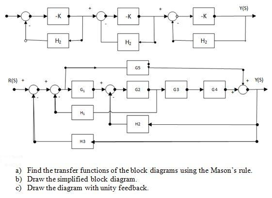
Solved: Find The Transfer Functions Of The Block Diagrams ...
Block diagram of the signal-flow for a common feedback loop. [1] : 118 Audio feedback (also known as acoustic feedback , simply as feedback , or the Larsen effect ) is a special kind of positive loop gain which occurs when a sound loop exists between an audio input (for example, a microphone or guitar pickup ) and an audio output (for example ...
Solved: Reduce The Block Diagram Shown To Unity Feedback F ...
This tutorial will describe step-by-step how to write a grass shader for Unity. The shader will take an input mesh, and from each vertex on the mesh generate a blade of grass using a geometry shader.To create interest and realism, the blades will have randomized dimensions and rotations, and be affected by wind.To control the density of the grass, tessellation will be used to …
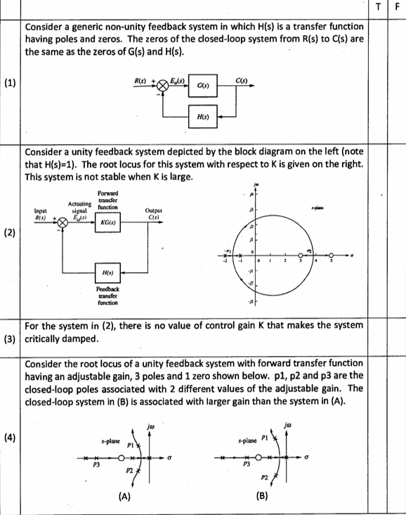
Solved: Consider A Generic Non-unity Feedback System In Wh ...
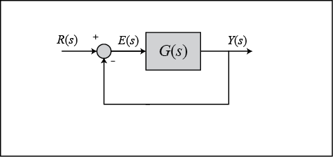
Block Diagram of a Unity-Feedback Control System. E(s) R(s) C(s) G(s) + − Ch11-9780240811284.indd 11-6 3/24/10 10:05:59 PM. Lobontiu 978--240-81128-4 00011 11.2 Block Diagrams and Feedback Control Systems 11-7 Example 11.1 a. Convert the control system described by the block diagram of Figure 11.8(a) into a

The Design of Feedback Control Systems
Reduce the block diagram to unity feedback form and find the system characteristic equation. F1 U.B Deepak 28.01.2020 D15.1 answer · Top answer: "System characteristic equation: 1 + G(s) H(s) = 0 Now, G(s) ( = frac{1}{{s + 1}} cdot frac{1}{s}) (forward path) (Hleft( s right) = frac{1}{{s ...

Solved: 4. A Unity Feedback System Has The Closed-loop Tra ...
Block Diagram Y x x z Y Equivalent Block Diagram X y X + y----€.-Fig. 7-6 Continued 7.6 UNITY FEEDBACK SYSTEMS Definition ZT: A unity feedback system is one in which the primary feedback b is identically equal to the controlled output c. EXAMPLE 7.6.' H = 1 for a linear, unity feedback system (Fig. 7-7). / Fig. 7-7
Active Noise-Canceling Headphones under Audio Filters ...
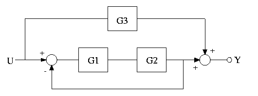
3.19 Find the transfer functions for the block diagrams in Fig. 3.54: Solution: Simplify the block diagram as above, 1 2 1 () 1 Ys G Ts G ... 3.24 For the unity feedback system shown in Fig. 3.59, specify the gain K of the proportional controller so that the output ( ) has an overshoot of no more than 10% in response to a uni yt

Inked 2
Unity feedback systems are so often used for analysis because most (or all?) systems can be transformed into a unity-feedback system through block-diagram manipulations. The unity-feedback system therefore provides a convenient standard framework for understanding many feedback systems. Share Cite Follow edited Jun 12 '21 at 19:14

Solved: A Unity-feedback Control System Is Represented By ...
The block diagram of a system is illustrated in the figure shown, where X(s) is the input and Y(s) is the output. ... A unity feedback control system is characterized by the open-loop transfer function G(s)= The Nyquist path and the corresponding Nyquist plot of G(s) are shown in the figures below.

Classical PID controller in a unity feedback block diagram ...
9. The open loop transfer function of a unity feedback system is given by G(s)= 1 s(1+𝑠)2. Sketch the polar plot and determine the gain margin and phase margin. 10.Consider a unity feedback system having an open loop transfer function G(s)= 𝐾 s(1+0.5𝑠)(1+4𝑠) determine the value of K so that

Solved: Problem 2) The Block Diagram Of A Control System I ...
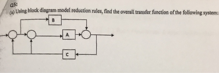
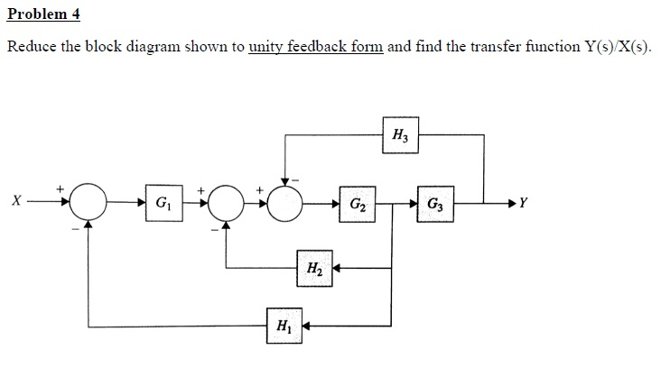
3-4. Reduce the block diagram shown in Fig. 3P-4 to unity feedback form and find the Y/X. Figure 3P-4 3-5. The aircraft turboprop engine shown in Fig. 3P-5(a) is controlled by a closed-loop system with block diagram shown in Fig. 3P-5(b). The engine is modeled as a multivariable system with input

Feedback Control of Mechanical Systems | Top Hat
Transform the non-unity feedback system into a unity feedback system ... Block Diagram Transformation ... transfer function block; apply Lecture 16 results!42 pages
a2: Consider a unity positive feedback control system ...
The frequency response of H2 is inaccurate for frequencies below 2e4 rad/s. This inaccuracy can be traced to the additional (cancelling) dynamics introduced near z=1. Specifically, H2 has about twice as many poles and zeros near z=1 as H1.As a result, H2(z) has much poorer accuracy near z=1, which distorts the response at low frequencies. See the example Using the Right Model Representation ...

4-4. Reduce the block diagram shown in Fig.4P-4 to unity ...
By reducing the unity feedback block diagram, the closed-loop transfer function with a proportional controller becomes: (3) Recall from the Introduction: PID Controller Design page, a proportional controller, , decreases the rise time, which is desirable in this case. For now, use equal to 100 and a reference speed of 10 m/s.

In my profession a lot of people ask me where I am coming from. If I have time I explain them that I come originally from that place we call Spain, but that I don’t feel Spanish, I just feel a citizen of the world, a person, a human being… that I don’t see nationalities, I see people, and that the people that are trying to do “good†in this world they are my brothers, no matter where they are coming from. We are just a humanity, and any other category is limiting for starting to think about commonwealth and peace. Ying yang, the unity.
Transcribed image text: Consider the following block diagram for problems 1 & 4: controller plant u C(s) Ps) Problem (Only do (c)); (Refer to the unity feedback block diagram above) Suppose that unity feedback is to be applied around the following open-loop systems. Use Routh's Stability Criterion to determine whether the result- ing closed-loop systems (from r(t) to y()) will be stable.

Multiple Choice
8.3.2 Manipulating Block Diagrams A block diagram for a system is not unique, meaning that it may be manipulated into new forms. Typically a block diagram will be developed for a system. The diagram will then be simplified through a process that is both graphical and algebraic. For exam-ple, equivalent blocks for a negative feedback loop are ...
Control Tutorials for MATLAB and Simulink - Extras: Type 2 ...
158 BLOCK DIAGRAM ALGEBRA AND TRANSFER FUNCTIONS OF SYSTEMS [CHAP. 7 Fig. 7-6 Continued 7.6 UNITY FEEDBACK SYSTEMS Definition 7.7: A unity feedback system is one in which the primary feedback b is identically equal to the controlled output c. EXAMPLE 7.6. H = 1 for a linear, unity feedback system (Fig. 7-7). Fig. 7-7 Any feedback system with only linear time-invariant elements can be put into ...
Ch: Calculating Transfer Function
The single-loop, unity-feedback block diagram at the top of this web page will be used throughout this example to represent the problem under consideration. With unity feedback, the reference input R(s) can be interpreted as the desired value of the output, ...

control - Why is unity feedback used? - Electrical ...
Block Diagram of Feedback System. The figure here shows the block diagram of the control system with feedback: The major concerning factors of a feedback system include sensing, controlling and actuating the process inside the system. More specifically, the reasons for implementing feedback in any electronic circuit are as follows:

Block diagram of the unity feedback control systems ...
Definition 4.1: The closed-loopsystem transfer function for non unity feedback is defined by If we go around the loop of the non unity feedback block diagram presented in Figure 4.7b, we will encounter two transfer function and . The product is called the loop transfer function. This can be formally stated in the form of a new definition.
Solved: Reduce The Block Diagram Shown To Unity Feedback F ...
K. Webb ESE 499 3 Block Diagrams In the introductory section we saw examples of block diagrams to represent systems, e.g.: Block diagrams consist of Blocks - these represent subsystems - typically modeled by, and labeled with, a transfer function Signals - inputs and outputs of blocks - signal direction indicated by arrows - could be voltage, velocity, force, etc.
Closed Loop unity feedback control for motor on Arduino
Block diagram for low power stability with idealised feedback. The open loop transfer function is KG n and the closed loop transfer function is KG n /[1 – KG n ], where we have absorbed the power level into the definition of the feedback gain K .
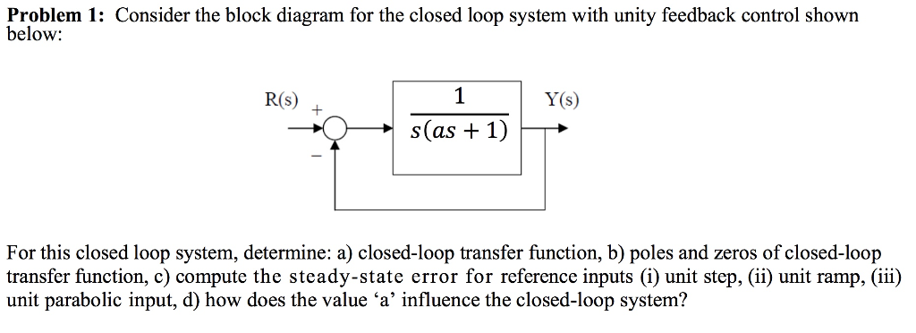
Solved: Problem 1: Consider The Block Diagram For The Clos ...
A simple feedback loop is shown in the diagram. If the loop gain AB is positive, then a condition of positive or regenerative feedback exists.. If the functions A and B are linear and AB is smaller than unity, then the overall system gain from the input to output is finite, but can be very large as AB approaches unity. In that case, it can be shown that the overall or "closed loop" gain from ...

Transfer function algebra - x-engineer.org
Transcribed image text: (Refer to the unity feedback block diagram above) Suppose that unity feedback is to be applied around the following open-loop systems. Use Routh's Stability Criterion to determine whether the result- ing closed-loop systems (from r(t) to y(t)) will be stable.
Solved: Consider the unity feedback system described in ...
Problem 30. A unity-feedback system is shown in the block diagram below: K(s + ! ) s(s + 1)(s + 10) a. Find so the system will have a settling time of 4 seconds for large values of K. The expression for 2% settling time Ts is Ts = 4 !n = 4 sec =) !n = 1; (10) where !n is the REAL part of a complex pole location. The closed-loop TF is C(s) R(s ...
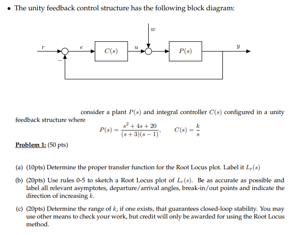
The unity feedback control structure has the | Chegg.com
Block Diagram Simplification –Example 1 Rearrange the following into a unity‐feedback system Move the feedback block, * O, forward, past the summing junction Add an inverse block on 4 Oto compensate for the move Closed‐loop transfer function: 6 O L 1 * O * O ) O 1 O * O L ) O 1 O * O K. Webb MAE 4421 16
[Solved] 27 For the unity feedback system shown in Fig.551 ...
A unity feedback system is a control system that has no component in the feedback path . If W = V = 0: General case: Categories. Categories. Information processing structures.

Determine The Transfer Function Of The Above Block ...

Block diagram of the unity feedback control systems ...
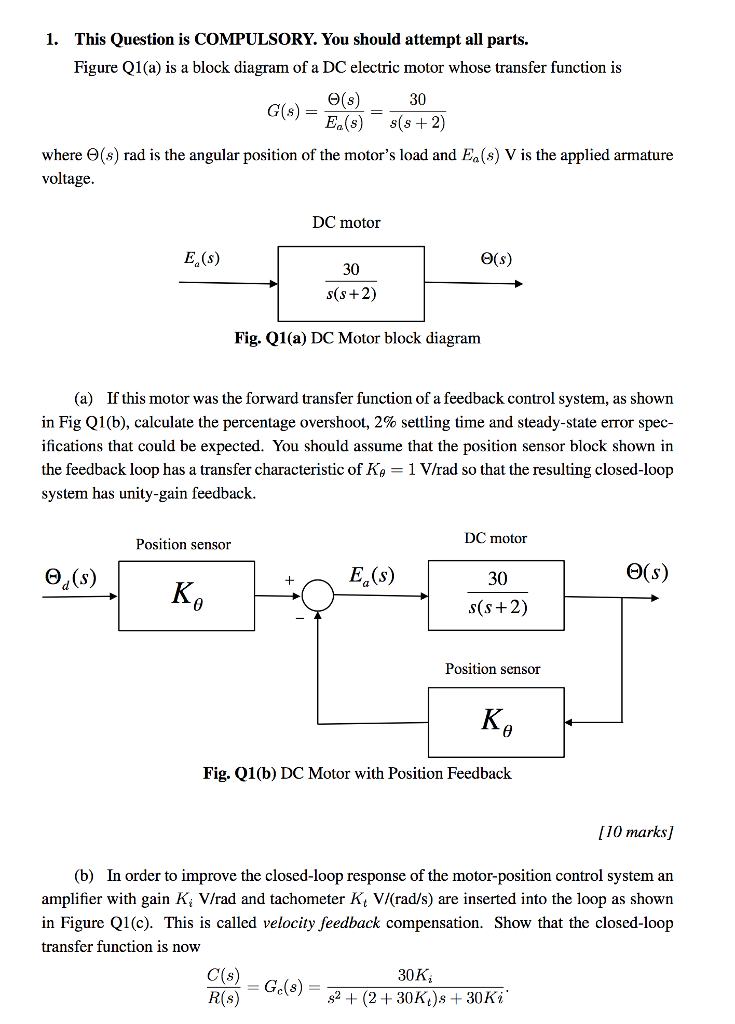
Solved: Figure Q1 (a) Is A Block Diagram Of A DC Electric ...
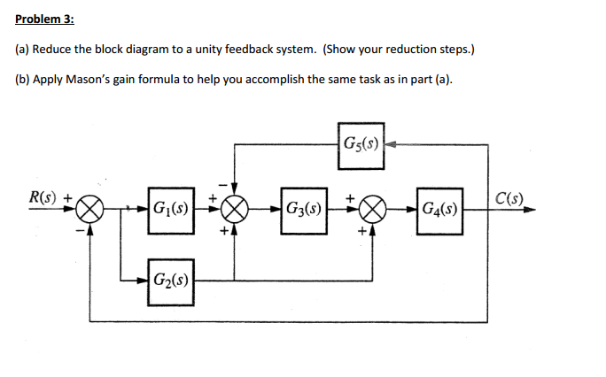
Solved: Reduce The Block Diagram To A Unity Feedback Syste ...

Simple unity feedback control system. | Download ...
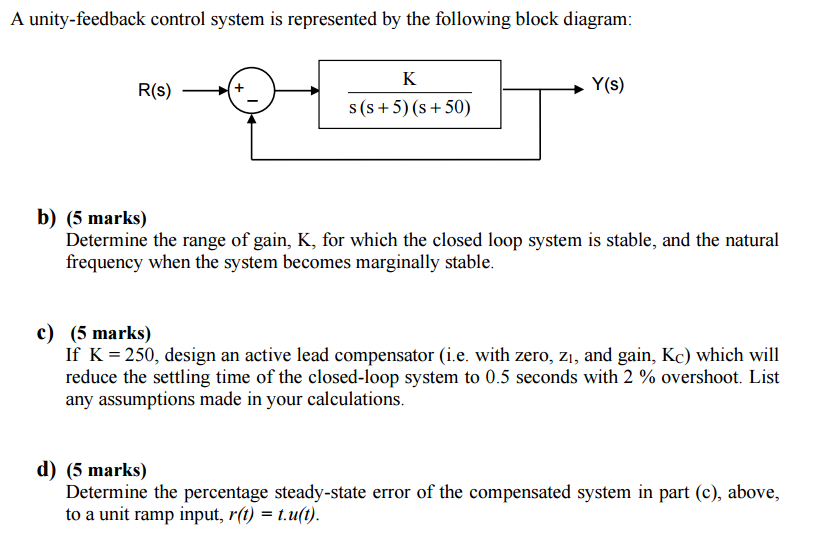
Solved: A Unity-feedback Control System Is Represented By ...
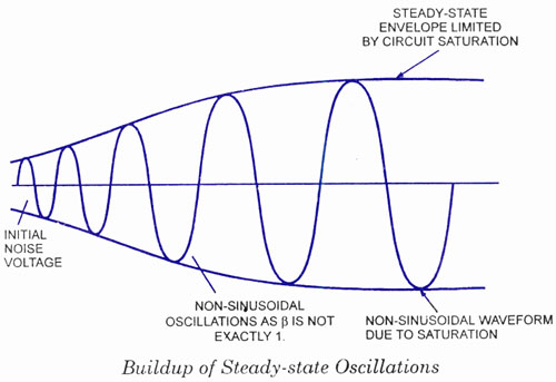
Oscillator operation-working-feedback circuit, block diagram
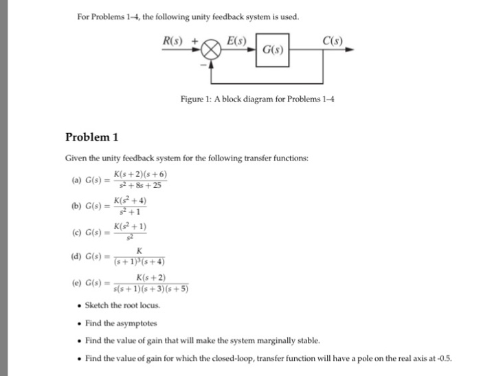
For Problems 1-4, the following unity feedback system ...
Unity feedback system. | Download Scientific Diagram
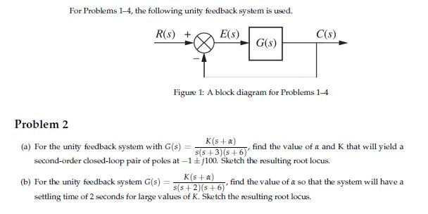
Solved: For Problems 1-4, The Following Unity Feedback Sys ...

4-4. Reduce the block diagram shown in Fig.4P-4 to unity ...

Block diagram of a 2×2 nonlinear multivariable feedback ...
0 Response to "39 unity feedback block diagram"
Post a Comment