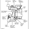
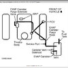
39 vacuum hose routing diagram
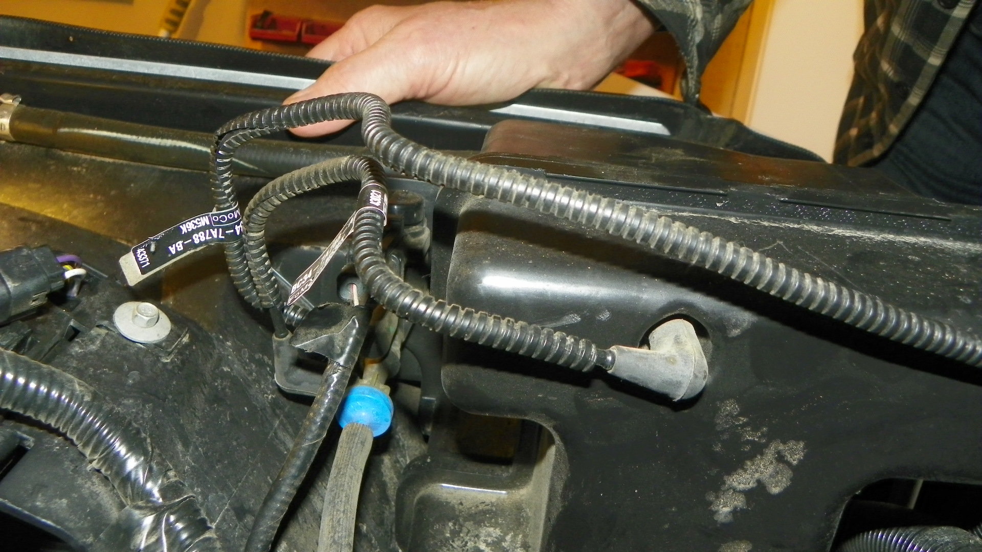
FREE Vacuum Hose Routing Diagrams For example, we have the following 1975 Vacuum Hose Routing Diagrams available FREE. Many other years are also available. 1975 - 225 - Federal - Canada (Early) - California: 1975 - 318 - Federal - Canada - Automatic: 1975 - 318 - Federal - Canada (Manual) So I have an update. I spent some time tracing the vacuum hose routing in the car, and comparing it to the VW Vacuum Hose Routing Diagram. In my first post I mentioned a 'stray' hose that was disconnected, and as it turns out the hose is not on the diagram. On closer inspection, it originates from a T-Piece in the N75 to VNT Actuator Line.
diagram does not match the master Car Standard Wire Code Chart. If your vehicle has a color coded wire that does not match a diagram you should consult the other diagrams contained in the manual for a possible match. Example of possible errors. The color coded wiring diagrams are provided for illustration purposes only. Only the wire
Vacuum hose routing diagram
vacuum hose routing. ... the vacuum hose in question starts at the VOES runs to the carb then has a plastic Y part of the Y goes to the base of the carb and the other part of the Y goes to the petcock area but is plugged with a bolt. i know a pic will explain it better. i will see what i can do.. Diagrams of how the vacuum hoses are routed can be found in the Delorean manuals, online, and in the car itself. On the inside of the lower engine compartment ... Series I Tech Garage - Vacuum hose diagram - Please I need a vacuum hose diagram for my 2006 RX8(automatic). I live in a small island and the mechanics here ...
Vacuum hose routing diagram. Discussion Starter · #1 · Oct 15, 2010 (Edited) Hey guys, Just a couple days ago we had a guy who was flustered because he couldn't figure out where his vacuum lines were supposed to go after installing a new motor. I figured that there are probably more than just him who don't understand the Routing diagram listed underneath the hood, so i ... Oct 15, · I know what the stock diagrams show, Quadrajet Vacuum hose routing. I know what the stock diagrams show, That switch had like 5 hoses going to it. A ported vacuum source, a manifold vacuum source, a line going to some switch on the rear of the carb, a vacuum advance and some crazy vacuum retard. Mar 25, · News: As of April 1, All ... This is NOT 100%... But as close as I can get to it since " Variations " due to different Models / Year and YES, there are differences. If any corrections n... Vacuum Hose Routing Diagram; Results 1 to 10 of 10 Thread: Vacuum Hose Routing Diagram. Thread Tools. Show Printable Version; 06-22-2015 04:33 PM #1. VroomTT. View Profile View Forum Posts View Blog Entries View Articles Veteran Member Three Rings. Join Date Nov 21 2013 AZ Member # 131209 Location
Vacuum Hose Diagram. Jump to Latest Follow 1 - 5 of 5 Posts. K. kim.m.anthony · Registered. Joined 11 mo ago · 25 Posts . Discussion Starter · #1 · 11 mo ago. Only show this user ... Looking for a vacuum hose diagram for a 2004 Silverado 1500 6.0L I can hear a vacuum leak on the drivers side of the engine, cannot pin point it but my truck has 370,000km so ill just replace all the vacuum lines Did a vacuum leak test, i sit from 15-16.8 psi jumps back and forth in that area as ... Click here to view technical diagram. 1970-73 Camaro AC Refrigerant Hose Routing Click here to view technical diagram. 1970-81 Camaro & Firebird Kick Panel Fresh Air Block-Off Plenum Assembly & Cover Click here to view technical diagram. 1971-74 Camaro AC Heater Ducting Click here to view technical diagram. 1974-75 Camaro Air Conditioning Outlets Jun 23, 2015 · Refer to the drive belt routing diagram located on the radiator shroud. Step 10 – Connect the pressure hoses and Tee fitting. Ensure that the O-rings on the hard lines are not worn out. Use a high pressure hose to connect the Hydroboost unit to the gearbox. Thread the hard line of the hose into the driver's side of the Hydroboost unit.
Tweet. Access our free Vacuum Diagrams Repair Guide for GM Full-Size Trucks 1980-1987 through AutoZone Rewards. These diagrams include: Fig. 1: Vacuum hose schematic-1980. Fig. 2: Vacuum hose schematic-1980. Fig. 3: Vacuum hose schematic-1980. Fig. 4: Vacuum hose schematic-1980. vacuum hose routing diagram need to know where a line goes. from the intake tube between the throttle body and the - Mercury 1995 Mystique question 72 vacuum diagram. 78 vacuum diagram without auto-temp control. 78 vacuum diagram with auto-temp control. 78 emissions vacuum diagram for engines with thermactor. 86 alarm system electrical diagrams . 88 EEC electrical diagram . 87-88 radio electrical diagrams . 64-66 Convertible System Hose Diagram Location. Morgantown, WV. TDI. 2001 Golf TDI. Aug 9, 2010. #1. After using aNUT's very helpful thread to help me re-do my vacuum lines, I decided to re-make his diagrams into more complete, readable, printable, noob-friendly forms. I used his diagrams in combination with TonyJetta's labels. They're color coded so that you don't start looking at ...
Fig. 5: Vacuum hose routing for the TCS system 1970 6-cylinder engines; Fig. 6: Vacuum hose routing for the TCS system 1970 8-cylinder engines; Access our GM Firebird 1967-1981 Vacuum Diagrams Repair Guide by creating an account or signing into your AutoZone Rewards account. Once you sign in, follow these instructions to access our Repair Guides.
Time: author: bamomer quadrajet carb diagram vacuum I have a Best Answer: off the back there is big port,goes to pcv and.Oct 15, · The manifold vacuum bottom center should have been connected to the hose that went to the T in the hoses going to the vacuum actuators in the snorkels of the original dual snorkel air cleaner.
C O M. Below is a collection of Volvo vacuum connection diagrams I have located or (some) created from Volvo service manuals and other sources. I'm always looking for more diagrams to help our fellow Volvo owners who are having a tough time locating these. Under Hood Vacuum Label Collection here. If you can help supply more Volvo vacuum ...
Jan 01, 2005 · The section of the engine which contains the propeller shafts and reduction gears. Includes items such as drives for hose mounted accessories, etc. If applicable, the section of the engine which uses mechanical force, through a gear-driven system, to drive front mounted propulsors which provide the majority of the energy generated.
71 emission vacuum hose diagram - CorvetteForum - Chevrolet Corvette ... 1979 Ford 370 engine vaccum diagrams. 1971 - 1972 Corvette Headlight & Wiper Door Vacuum Hose Kit. Typical Vacuum Hose Kit - Diagram View - Chicago Corvette Supply. I am putting a polished TBI plenum, and fuel rails on my 1988 C4 ...
Mar 26, 2009 · Vacuum Hose Routing/Diagram. Thread starter. kimcheefists. Start date. Mar 26, 2009. Mar 26, 2009. #1. Well my car idles kinda crappy and I was thinking that I had a boost leak. I checked my vacuum hoses first and found a hose coming from the intake manifold that wasn't connecting to anything.
Registered. Joined Feb 16, 2009. ·. 64 Posts. Discussion Starter · #1 · Nov 16, 2009. Only show this user. I have a 1989 s10 with a 4.3 tbi and i need a vacuum routing diagram. I have most of the vacuum lines hooked up but i still have a few that are unhooked and one has a bolt in it.
2004 2006 Honda Rancher 350 Four Wheeler Carburetor Repair 2005 Ifixit. 2001 Honda Fourtrax Rancher 350 4x4 Es Trx350fe Carburetor Parts Best Oem Diagram For. Carb Hose Routing Honda Trx Atv Forum. 2004 2006 Honda Rancher 350 Four Wheeler Carburetor Repair 2005 Ifixit. The Vacuum Hoses On My 2005 Honda 350 Rancher Are Rotted Off Fixya.
The vacuum hose line routing diagram can be obtained from most chevrolet. Asked in chevy silverado, chevy s-10, ford f-150 need a vacuum hose diagram for a 1996 chevy. Where can we obtain a vacuum line schematic for a 1997 chevy s10 pu. We have fire to the ignition, but no electricity to the injectors. SUZUKI BURGMAN 400 SERVICE MANUAL 2016.
Need a vacuum hose routing diagram for a chevy s10 4.3L vortec engine - Answered by a verified Chevy Mechanic We use cookies to give you the best possible experience on our website. By continuing to use this site you consent to the use of cookies on your device as described in our cookie policy unless you have disabled them.
Apr 16, 2014 — I am just wondering if any of you guys have a complete vacuum hose diagram for the 1971 Javelin AMX....
Carter quadrajet 4 barrel vacuum hose diagram?. on to the manifold but I can't find where it hook up. help Read More. 1984 720 vacuum hose. Quadrajet vacuum lines? - Third Generation F-Body Message Boards It is very hard to tellif I have all the vacuum hoses hooked up correctly,not to mention do I even have all the hoses.
Jan 13, 2022 · I need vaccum hose routing for 2001 v6 escape. Disconnect the brake booster vacuum hose from the brake booster assembly (located below and behind the fuse box on the driver's side). One of the two vacuum lines/hoses will have engine vacuum. Here are some ford ranger vacuum hose guides. 2001 Ford Focus Radiator Hose Diagram PDF Download.
3,841 Posts. #20 · Apr 21, 2020. Only show this user. Nissan often has metal vacuum lines on engines that work on multiple applications (i.e. Federal vs California emissions, AT vs MT, etc.), so there may be metal vacuum lines on your engine that never had vacuum hoses to them.
Following are vacuum diagrams for most of the engine and emissions package combinations ... 1: Vacuum hose routing — 1979–80 Federal vehicles (all models) ...
At the bottom of this web site there is also a 2003 Dodge Ram Vacuum Diagram photo gallery, if the picture above is inadequate for you. Tags: #2003 dodge ram 1500 4.7 vacuum line diagram #2003 dodge ram 1500 vacuum diagram #2003 dodge ram 1500 vacuum line diagram #2003 dodge ram 4.7 vacuum diagram #2003 dodge ram vacuum lines #vacuum hose ...
Vacuum Diagrams This is not an automated service. Each Diagram that is requested has to be hand selected and sent. As this is a free service it receives an overwhelming amount of requests and may take up to a week or longer for a response. Just submit a request for the Vacuum diagram you want.
Generally, this procedure should apply to all 1994, 1995, 1996, and 1997 T-Birds & Cougars with the 4.6L V8 engine. The process will be similar for 3.8L V6 and 5.0L V8 equipped cars, so refer to your underhood vacuum hose routing label for more details. There is a minor difference for the 1994/1995 4.6L cars, if your car is 94 or 95, see the ...
This article contains underhood views or schematics of vacuum hose routing. Use these vacuum diagrams during the visual inspection in appropriate BASIC ...56 pages
Vacuum hose routing diagram 2.8 5v v6 Audi Quattro sedan awd - Audi 1998 A6 question
Lt1 vacuum line diagram Sami 27112020 27112020 Lt1 vacuum line diagram Starting at the driver-side frame rail is the easiest route to fueling your LT1. Lt1 engine lt1 vacuum hose diagram. Steering Column Exploded View. Z28 Front Bumper Exploded View. When working under the hood pay close attention to the routing and placement of every hose.
Oct 10, 2020 · Even so, it's important to consult the vacuum hose routing diagram of the vehicle emissions label (usually on the air filter box) and check: The condition and fit of each vacuum hose. The vacuum hoses should have a tight fit around the metal line or vacuum port that they're connected to. Vacuum hose routing. This involves making sure they are ...
Apr 26, 2011 · Vacuum Hose Routing Diagram (1993 5.0L V8 E150, E250) Vacuum Hose Routing Diagram (1987 5.0L V8 E150, E250) How To Test The Alternator (1992-1993 Ford E150, E250, E350) OBD I Trouble Code Chart (1993 Ford E150, E250, E350)
Jun 10, 2020 — Hello, Here are the vacuum hose routing for you car in the diagrams below. Check out the diagrams (below). Please let us know if you need ...
Vacuum Hose Routing Diagrams. Below is a list of all vacuum diagram that are currently available. Make sure you look at the correct diagram for your engine ...
McMaster-Carr is the complete source for your plant with over 700,000 products. 98% of products ordered ship from stock and deliver same or next day.
Vacuum lines dry out and crack over time. Often they are routed under the intake and/or close to HOT exhaust. Here is a quick tip that can help you route t...
Emission Control Vacuum Hose Routing. Vacuum hose routings and emissions inspection information. Buy Now . Heavy Truck Repair Manual. Medium/heavy-duty repair information and heavy truck components ... Heavy Truck Wiring Diagram Manual. Two-volume medium/heavy-truck wiring diagrams guide. Buy Now . Interior Panel Removal Guide. Illustrated ...
I have an 86 RTE 4Runner and it doesn't quite match the diagrams. It looks like a mix of the 84RE and the RTE diagrams. I've got an apparently broken VSV (the hoses sort of match the middle, non-highlighted part of the 84 diagram) On the EFI body there is a module with a plastic spring loaded adjuster knob that matches the 84 diagram.
Q: Vacuum Hose Diagrams for 1968. Hello all! I am in the midst of rebuilding my 1968 firebird 400 conv. (little by little). I am working on the engine for now, while I am waiting for my Year One parts to arrive… I read the message a little earlier about overheating. Which unfortunately, my poor car is doing!
Diagram your Quadrajet carburetor Rochester Quadrajet carburetor identification numbers. The ports provide a vacuum signal to the. vacuum hose diagram to rochester 4 bbl carb for 79 chevy pick up have a 4bbl rochester quadrajet i need to know - Chevrolet C Find solutions to your vacuum lines quadrajet carburetor question.
Installation Diagram Valve 2. Valve 1 Fuel tanks above filter. head pressure should not exceed maximum PSI of filter. Fuel Tank (Pressure Side Installation) Install a shut-off valve when fuel tank is higher than filter. Fuel tank below filter. Do not exceed 5’ (1.5m) of lift. or 4 inches of mercury (inHg) of inlet piping restrictions. Fuel ...
Vacuum Hose Routing Diagrams. Below is a list of all vacuum diagram that are currently available. Make sure you look at the correct diagram for your engine and the location that the vehicle was originally sold. Some of them are actually not the right year, but I believe the hose routing is the same. Some of the diagrams are provided by Gary Donovan's site.
Connect a hose from the drain fitting to a drain or gutter. ... and that pipe will then pick up the tub before it hits the combo wye in the diagram. ... addition to a P-trap at each fixture, ask your local building inspector if she will accept air-admittance valves, aka vacuum-breaker V-200 type vents that are installed at the fixtures.
Series I Tech Garage - Vacuum hose diagram - Please I need a vacuum hose diagram for my 2006 RX8(automatic). I live in a small island and the mechanics here ...
Diagrams of how the vacuum hoses are routed can be found in the Delorean manuals, online, and in the car itself. On the inside of the lower engine compartment ...
vacuum hose routing. ... the vacuum hose in question starts at the VOES runs to the carb then has a plastic Y part of the Y goes to the base of the carb and the other part of the Y goes to the petcock area but is plugged with a bolt. i know a pic will explain it better. i will see what i can do..









0 Response to "39 vacuum hose routing diagram"
Post a Comment