40 phasor diagram rlc circuit
Sep 18, 2021 · The phasor diagram shows the phase difference between voltage an current. The LCR circuit analysis can be understood better in terms of phasors. For drawing the phasor diagram for rlc series circuit the current is taken as reference because in series circuit the current in each element remains the same and the. Phasor Diagrams are a graphical way of representing the magnitude and directional relationship between two or more alternating quantities Sinusoidal waveforms of the same frequency can have a Phase Difference between themselves which represents the angular difference of the two sinusoidal waveforms.
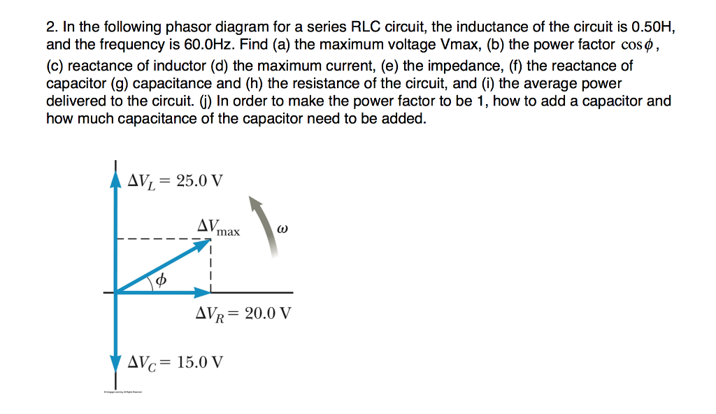
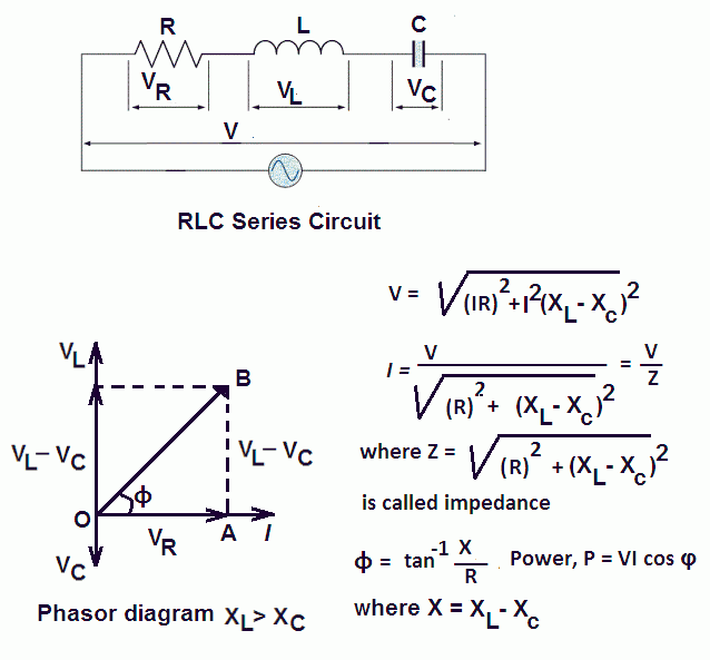
The phasor diagram for a series RLC circuit for capacitive (left), inductive (center) and pure resistive (right) impedance. The voltage vectors on the diagram produce a rectangular voltage triangle with a hypotenuse V T, vertical leg V L -V C and horizontal leg V R.

Phasor diagram rlc circuit
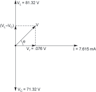
Question: (Figure 1) shows the phasor diagram for an RLC circuit. Figure 1 of 1 VLE VCP VRP Complete the diagram by adjusting the applied voltage phasor. Adjust the end point of the applied voltage phasor to complete the phasor diagram. The orientation and length of the phasors will be graded. You can draw unlabeled phasor (s) and move the ... To draw the phasor diagram of RLC series circuit, the current I (RMS value) is taken as the reference vector. The voltages across three components are represented in the phasor diagram by three phasors V R, V L and V C respectively. The voltage drop V L is in phase opposition to V C. As a result, this circuit is not commonly utilized as an evaluator of series RL circuit. Visit here to see the main differences between series and parallel RL circuits. Phasor Diagram. The vector (phasor) diagram can be used to show the main relationship between the voltage and currents in a parallel RL circuit.
Phasor diagram rlc circuit. Network Theory: Phasor Diagram of Series RLC Circuit Topics discussed:1) Phasor diagram of series RLC circuit.2) Voltage triangle of series RLC circuit.3) Im... Feb 24, 2012 · RL Circuit For drawing the phasor diagram of series RL circuit; follow the following steps: Step- I. In case of series RL circuit, resistor and inductor are connected in series, so current flowing in both the elements are same i.e I R = I L = I. So, take current phasor as reference and draw it on horizontal axis as shown in diagram. Step- II. An LCR circuit, also known as a resonant circuit, tuned circuit, or an RLC circuit, is an electrical circuit consisting of an inductor (L), capacitor (C) and resistor (R) connected in series or parallel. The LCR circuit analysis can be understood better in terms of phasors. A phasor is a rotating quantity. Current Vs Voltage Graph Parallel RL Circuit Phasor Diagram. The relationship between the voltage and currents in a parallel RL circuit is illustrated in the vector (phasor) diagram of Figure 2 and summarized as follows: The reference vector is labeled E and represents the voltage in the circuit, which is common to all elements.
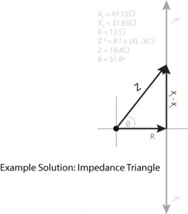
Steps to draw a Phasor Diagram. The following steps are used to draw the phasor diagram of RC Series circuit. Take the current I (r.m.s value) as a reference vector; Voltage drop in resistance VR = IR is taken in phase with the current vector; Voltage drop in capacitive reactance VC = IXC is drawn 90 degrees behind the current vector, as ... Sep 27, 2018 · For the given circuit diagram calculate the RLC series circuit impedance, current, voltage across each component, and power factor. Also draw the phasor diagram of current and voltage, impedance triangle, and voltage triangle. First of all, let me calculate the total impedance with the following formula Resistance: R=12\Omega An example of series RLC circuit and respective phasor diagram for a specific ω. The arrows in the upper diagram are phasors, drawn in a phasor diagram (complex plane without axis shown), which must not be confused with the arrows in the lower diagram, which are the reference polarity for the voltages and the reference direction for the current Phasor diagram for series RLC circuit Example: for the circuit shown in figure (a), draw the phasor circuit , impedance diagram and voltages phasor diagram. V=50∟0, so the phasor circuit is shown in figure (b). Z T =Z R +Z L +Z C o. Impedance diagram is shown in figure (c). V R =IZ R
The phasor diagram of series RLC circuit is drawn by combining the phasor diagram of resistor, inductor and capacitor. How is the sinusoidal response of a series RLC circuit determined? The series RLC circuit above has a single loop with the instantaneous current flowing through the loop being the same for each circuit element. In this video, Phasor diagram representation of voltage and current for Series RC, RL and RLC circuit has been explained and the examples based on this phaso... Figure 2 Voltage vector (phasor) diagram for a series RLC circuit. The circuit's phase angle theta (θ) is always the angle that separates the circuit's current and the applied voltage source, as summarized in Table 1. The phasor diagram of series RLC circuit is drawn by combining the phasor diagram of resistor inductor and capacitor. P V L I LI dIdT So the entire power factor of the RL circuit is given by the power dissipated by the resistor along with the power absorbed by the inductor. This Demonstration shows a phasor diagram in an AC series RLC circuit.
students to get some practice with drawing phasor diagram and determining the unknown quantities for the given circuit. During the laboratory experiment students measure voltages across all components in a similar series RLC circuit and then draw the phasor diagram to obtain the resistance of the practical inductor and phase angles between ...
An RLC circuit (also known as a resonant circuit, tuned circuit, or LCR circuit) is an electrical circuit consisting of a resistor (R), an inductor (L), and a capacitor (C), connected in series or in parallel. This configuration forms a harmonic oscillator. 2.
In the circuit diagram the RMS value of supply voltage is equal to the vector addition of the voltage across inductor (V L), voltage across resistance (V R) & voltage across capacitor (Vc ). The phasor diagram for the circuit can be drawn which shown the magnitude as well as the phase relationship between the various voltages (V R, V L, Vc, Vs ...
Network Theory: Phasor Diagram of Parallel RLC Circuit Topics discussed:1) Phasor diagram of Parallel RLC circuit.2) Current triangle of Parallel RLC circuit...
Rl Circuit Phasor Diagram. Here are a number of highest rated Rl Circuit Phasor Diagram pictures upon internet. We identified it from obedient source. Its submitted by executive in the best field. We understand this kind of Rl Circuit Phasor Diagram graphic could possibly be the most trending subject afterward we share it in google plus or ...
Phasor diagram of parallel RLC circuit, I R is the current flowing in the resistor, R in amps. I C is the current flowing in the capacitor, C in amps. I L is the current flowing in the inductor, L in amps. I s is the supply current in amps. In the parallel RLC circuit, all the components are connected in parallel; so the voltage across each ...
Jul 23, 2021 · Because resistor exists in the circuit, the RL circuit will consume energy which is similar to RLC or RC circuits. ... Phasor Diagram of RL Circuit. The phasor diagram of a series RL circuit is represented as below: Phasor Diagram of RL Circuit. To draw a phasor diagram for the circuit, below are the steps to be followed ...
Feb 24, 2012 · Phasor Diagram of Series RLC Circuit. The phasor diagram of series RLC circuit is drawn by combining the phasor diagram of resistor, inductor and capacitor. Before doing so, one should understand the relationship between voltage and current in case of resistor, capacitor and inductor. Resistor. In case of resistor, the voltage and the current are in same phase or we can say that the phase angle difference between voltage and current is zero.
Phasor Diagram for a Series RLC Circuit Phasor Diagram for a Series RLC Circuit (Reference: electronics-tutorials.ws) The voltage vectors produce a rectangular triangle, as shown in the phasor diagram on the right-hand side, with a hypotenuse V S, horizontal axis V R, and vertical axis V L - V C.
RLC Parallel circuit is the circuit in which all the components are connected in parallel across the alternating current source. In contrast to the RLC series circuit, the voltage drop across each component is common and that's why it is treated as a reference for phasor diagrams.
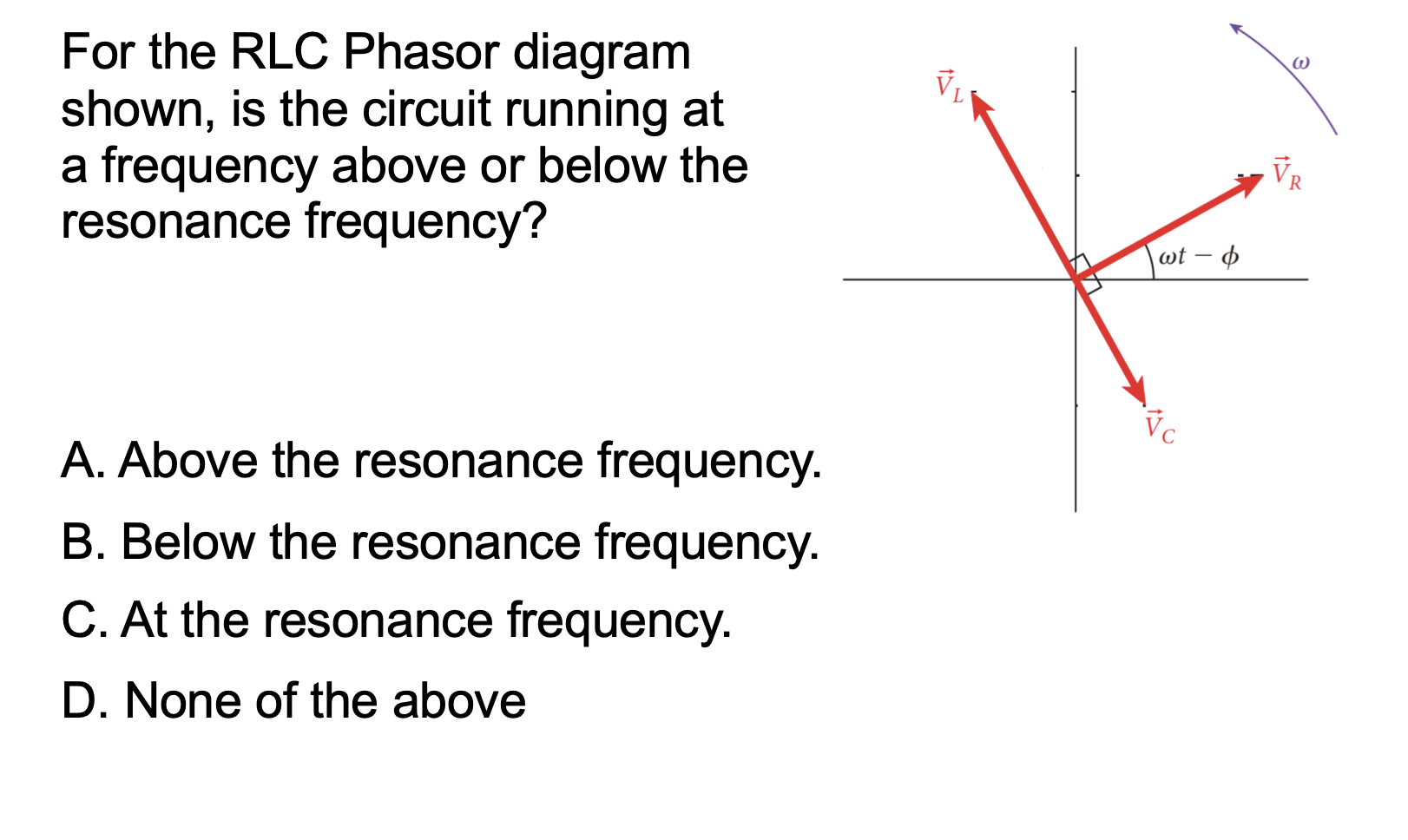
The nature of the phasor diagram of a series RLC circuit depends on the frequency f of the applied signal in relation to the frequency of resonance f0. Three different cases may be considered: (i) f = fr, (ii) f < fr, and (iii) f > fr. with f = f0, the reactance X L of inductor L equals the reactance of capacitor C.
Jul 19, 2011 · This Demonstration shows a phasor diagram in an AC series RLC circuit The circuit consists of a resistor with resistance an inductor with inductance and a capacitor with capacitance The current in an RLC series circuit is determined by the differential equationwhere and is the AC emf driving the circuit The angular frequency is related to the frequency in hertz Hz by In this Demonstration the
Phasor diagram, Circuit Diagram, Formula | Alternating Current (AC) - Resonance in series RLC Circuit | 12th Physics : Electromagnetic Induction and Alternating Current Posted On : 24.03.2019 08:39 pm
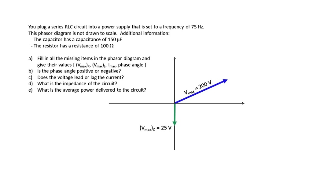
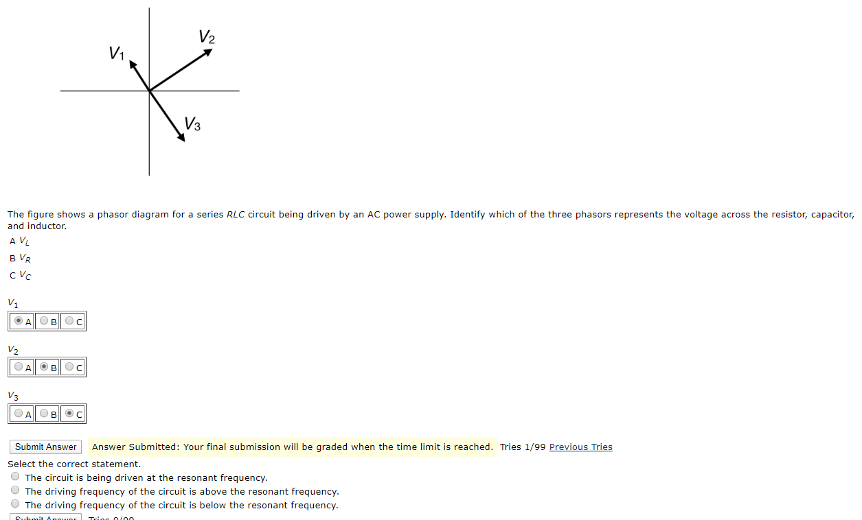
Steps to draw the Phasor Diagram of the RLC Series Circuit. Take current I as the reference as shown in the figure above; The voltage across the inductor L that is V L is drawn leads the current I by a 90-degree angle.; The voltage across the capacitor c that is V c is drawn lagging the current I by a 90-degree angle because in capacitive load the current leads the voltage by an angle of …
As a result, this circuit is not commonly utilized as an evaluator of series RL circuit. Visit here to see the main differences between series and parallel RL circuits. Phasor Diagram. The vector (phasor) diagram can be used to show the main relationship between the voltage and currents in a parallel RL circuit.
To draw the phasor diagram of RLC series circuit, the current I (RMS value) is taken as the reference vector. The voltages across three components are represented in the phasor diagram by three phasors V R, V L and V C respectively. The voltage drop V L is in phase opposition to V C.
Question: (Figure 1) shows the phasor diagram for an RLC circuit. Figure 1 of 1 VLE VCP VRP Complete the diagram by adjusting the applied voltage phasor. Adjust the end point of the applied voltage phasor to complete the phasor diagram. The orientation and length of the phasors will be graded. You can draw unlabeled phasor (s) and move the ...
![Solved] The phasor diagram for an RLC circuit is shown in ...](https://s3.amazonaws.com/si.question.images/image/images15/1307-P-M-P-Q-M(1118).png)










0 Response to "40 phasor diagram rlc circuit"
Post a Comment