35 abb vfd wiring diagram
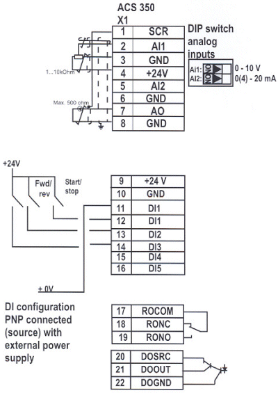
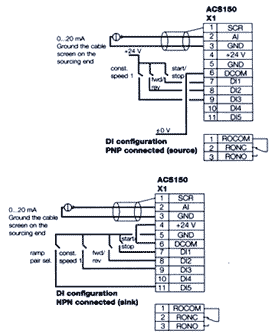
27 Oct 2021 — Default I/O connection diagram (ABB standard macro) . ... conduit increases the likelihood of VFD faults or warnings.268 pages Abb Vfd Control Wiring Diagram 11.11.2018 5 Comments controlled environment that is suitable for the selected enclosure. - Wiring Drive Identification. Use the following chart to interpret the type code found on the and control wiring. General wiring. 1. ABB Standard Macro.
Wiring diagram schem Collection of abb vfd wiring diagram. A wiring diagram is a streamlined traditional pictorial representation of an electrical circuit. It reveals the components of the circuit as simplified forms, and also the power as well as signal connections in between the gadgets
Abb vfd wiring diagram
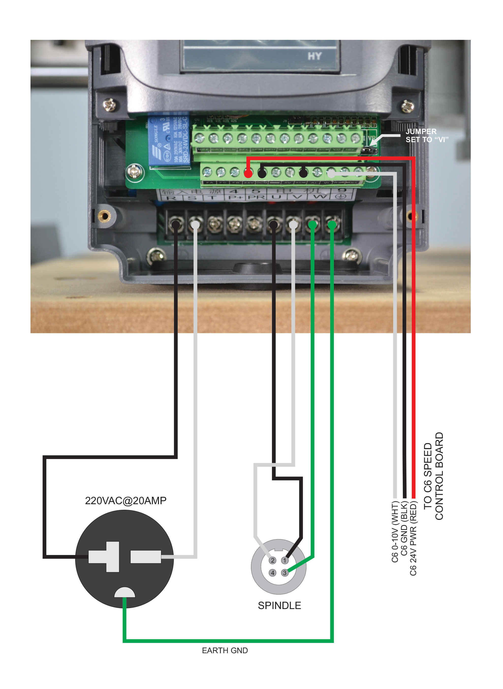
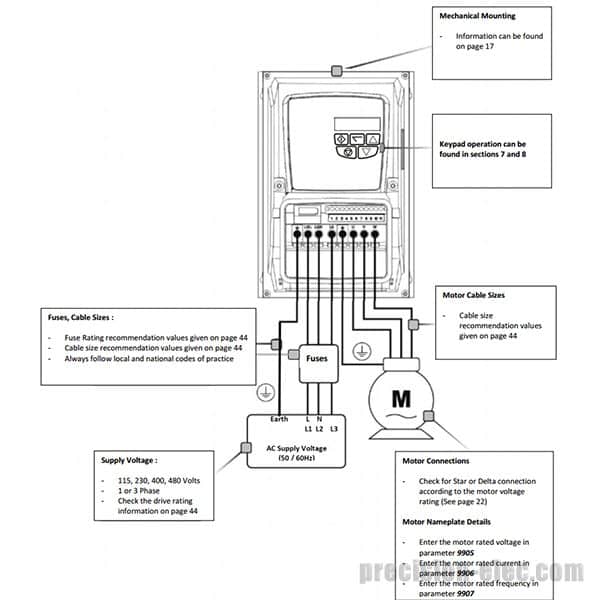
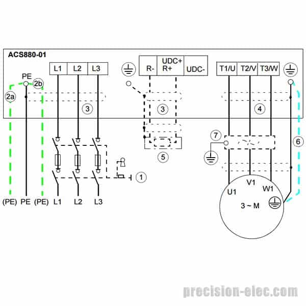
VFD wiring. 1. Main circuit wiring. The VFD main circuit terminals shown as below Figure. (1) The VFD's three phase AC input terminals (r/l1, s/l2, t/l3) The power line's input terminals connect to 3 phase AC power through line protection or leakage protection breaker, it does not need to consider the connection of phase sequence. List of related manuals. You can find manuals and other product documents in PDF format on the Internet. ... ABB Drives, ACS 320 Variable Frequency Drive.444 pages VFD Installation Instructions The block diagram below shows a typical VFD installation. This diagram shows the wires that supply power to the VFD, the wires that provide voltage from the VFD to the motor, and all the necessary input and output signals that the VFD needs for operation.
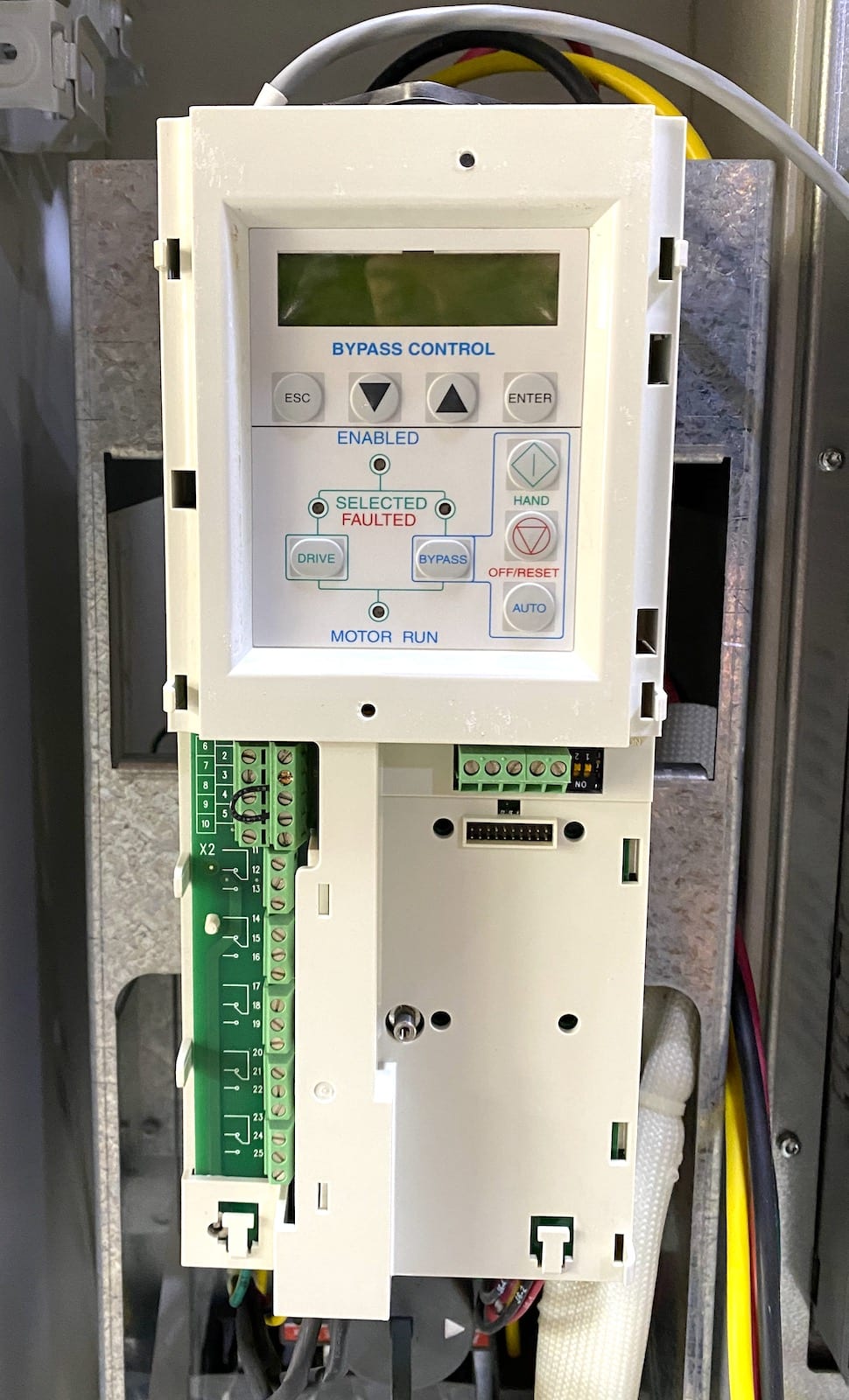
Abb vfd wiring diagram. A wiring diagram is a simplified conventional photographic representation of an electric circuit. Ensure that the control connections are wired according to the see section abb standard macro on page 72. So ideas if you like to secure the incredible shots related to abb vfd wiring diagram simply click save icon to store these graphics to your. From rolling metal, turning cement kilns, paper making, wire drawing, or running cable cars, our industrial DC drives give you the day-to-day reliability you need. DCS800-A The DCS800-A cabinet built industrial DC drive gives you the customization flexibility to engineer the exact DC drive solution for your processes. Abb Dol Starter Wiring Diagram Wiring Diagram Line Wiring Diagram. Abb Dol Starter Wiring Diagram Wiring Diagram Line Wiring Diagram ... ip65 rs components pole relays magnetic china magentic made in com page 869 synergy su 415v 2486 unit id 11976988073 vfd changeover bypass arrangement electrical4u machine or wall mounting star delta explained ... Wiring Overview (Supplement to ACH550-UH User's Manual) Connection Diagrams - Vertical E-Bypass ACH550 Vertical E-Bypass units are configured for wiring access from the bottom only. The following figure shows the Vertical E-Bypass wiring connection points. Refer to the ACH550-UH User's Manual for control connections to the drive. BP0054 ACH550
Saftronics Cv10 Basic Wiring Diagram. Abb Vfd Acs550 0 75 Kw To 355 3 Phase Ac Drives Voltage Variable Sd एब ब व एफड Frontline Technologies Coimbatore Id 16940456391. Saftronics Gp10 Basic Connection Diagram. Acs Acc Acp 601 Ac Drives 3 To 150 Hp 2 110 Kw 600 Hardware Manual. Abb Acs 600 Wiring Diagram Shoeshoneazreen. vfd 44 a 30hp @ 480vac dip consult manual for settings signal caale shield external ref ... abb scr scr 05/1 2/15 oate roi r02 ros ready drive running drive fault dip switch consult manual ... wiring diagram bypass project acs550 drive w/ classic 30hp 460vac n12 djr Collection of abb ach550 wiring diagram. Power connections wiring the controls 1. Ensure the motor is compatible for use with the ach550. Ground only at the drive end 4. Interconnecting wire paths may be revealed about where particular receptacles or fixtures should get on a common circuit. Abb Ach550 Wiring Diagram. Here are a number of highest rated Abb Ach550 Wiring Diagram pictures on internet. We identified it from reliable source. Its submitted by handing out in the best field. We say you will this nice of Abb Ach550 Wiring Diagram graphic could possibly be the most trending topic behind we allowance it in google help or ...
Abb Vfd Wiring Diagram Collection. Collection of abb vfd wiring diagram. A wiring diagram is a streamlined traditional pictorial representation of an electrical circuit. It reveals the components of the circuit as simplified forms, and also the power as well as signal connections in between the gadgets. A wiring diagram usually gives details about the… List of related manuals. Drive hardware manuals and guides. ACS355 drives user's manual. ACS355 drives with IP66/67 / UL Type 4x enclosure supplement.82 pages Acs550 Wiring Diagram. ABB ACS AC DRIVES - HP kW) to HP (75 kW) @ to V - HP kW) to HP ( kW) @ to V. wiring diagram at the back of this guide for additional wiring details. (ACS/ industrial or ACH/HVAC) and the same model (all ACS). Y. ACS User's Manual. ACS510 Drive Manuals. The IndustrialIT wordmark and Product names in the form. DriveIT are registered or pending trademarks of ABB.247 pages
Abb Acs800 Drive Wiring Diagram. ACS/U1/04 + C Drives ( to kW, to Depending on the external wiring, dangerous voltages ( V, V or V) .. Diagram. Wiring. **Grounding and Cabling of the Drive System EN • Grounding and Standard application macros with external control connection diagrams. Hardware manual.
Abb Vfd Control Wiring Diagram It is far more helpful as a reference guide if anyone wants to know about the homes electrical system. Abb vfd wiring diagram. A wiring diagram is a simplified traditional pictorial representation of an electric circuit. If in doubt contact your local ABB sales or service office.
Collection of abb vfd wiring diagram. Learn the basic wiring of variable frequency drives vfd with our electrician steve quist. Vfd el series is used only to control variable speed of 3 phase induction motors not for 1 phase motors or other purpose.
INSTALL wiring Wiring overview on page 1-18 and Install the wiring on page 1-23. CHECK installation Check installation on page 1-27. REINSTALL the cover Re-install cover on page 1-27. APPLY power Apply power on page 1-29. START-UP Start-up on page 1-30.
Abb vfd control circuit diagram furthermore pump panels moreover abb dc motor wiring diagram also loncin 50cc 4 wheeler wiring diagram as well as single phase ac motor control furthermore vfd schematic diagram pdf as well as 1a0p along with d3v furthermore vfd control wiring diagram in addition air pressor industry along with electrical drives ...
5. Install wiring WARNING! Ensure the motor is compatible for use with the ACH550. The ACH550 must be installed by a competent person. If in doubt, contact your local ABB sales or service office. Conduit kit Wiring R1…R6 drives with the UL type 1 Enclosure requires a conduit kit with the following items: • conduit box •screws • cover
Abb Acs 500 Manual Collection of abb vfd wiring diagram. A wiring diagram is a streamlined traditional pictorial representation of an electrical circuit. It reveals the components of the circuit as simplified forms, and also the power as well as signal connections in between the gadgets.
by AB BOVERI · 1995 — Knowledge of standard electrical wiring practices, electronic components, and electrical schematic symbols. • Minimal knowledge of ABB product names and ...77 pages
ABB Library is a web tool for searching for documents related to ABB products and services. Category. All Categories. ABB Channel Partners. ABB Industries and utilities ... Brief plus single and three phase wiring diagrams to configure QB to autotransformer buck boost Doc # 1TQC1932E0004. Circuit diagram. Circuit diagram. 2021-02-22. PDF. file ...
Maximum wiring size for each Air-Modulator is listed in the power and control wir-ing drawing, Form 100.04-PA1.2. A single point ground connection is provided in the Air-Modulator. Power wiring should be sized and installed in accordance with the National Electrical Code (N.E.C.). Copper wire is required for all power wiring connections to the Air-
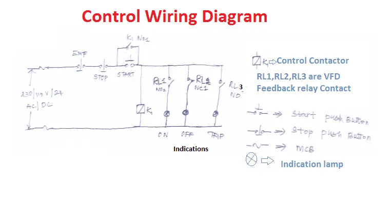
VFD Start Stop Wiring Diagram: I am here with giving you a VFD start stop wiring diagram for running a VFD through panel board push button and keypad of the VFD (It is called HMI).. Vfd is a short form of variable frequency drive or variable voltage variable frequency drive.The VFDs are working based on changing the input frequency and input voltage of the motor, we can change the speed of the ...
ABB VARIABLE FREQUENCY DRIVES 1.800.627.4499 ABB VFD SUPPLEMENTAL MANUAL RENEWAIRE.COM 5 WIRING OPTIONS WIRING SCHEMATICS INSTALLATION F1 "ON" SIGNAL CONNECTIONS If the ERV is equipped with Damper(s) and/or with just one VFD, the ON Signal control wires are connected to the low-voltage terminal strip in the ERV E-box. See Fig. 1.
abb vfd wiring diagram - What is a Wiring Diagram? A wiring diagram is a straightforward visual representation with the physical connections and physical layout of an electrical system or circuit. It shows what sort of electrical wires are interconnected and can also show where fixtures and components might be connected to the system.
Abb Vfd Wiring Diagram Reference Square D Vfd Wiring Diagram Free - Vfd Wiring Diagram Wiring Diagram includes several in depth illustrations that present the link of varied products. It contains guidelines and diagrams for different varieties of wiring strategies and other items like lights, home windows, and so forth.
Abb Ach550 Wiring Diagram - Abb Plc Wiring Diagram also Vfd Drives Wiring Diagram as well Abb Ai810 Wiring Diagram in addition Frequency Drive Wiring Diagram For as The ACH550 adjustable speed AC drive should ONLY be installed by a Note: For more technical information, contact the factory or your local ABB representative.
using the wiring diagram found on the fan motor's nameplate. This 220V wiring configuration also applies if the power source is 110V single phase. D) Once cable is properly connected inside the junction box, tighten the strain relief. Replace junction box cover. E) Run the rest of the motor control cable down near the wall mounted VFD. Using

10 HP ABB ACS800 Series NEMA 1 Enclosed Variable Frequency Drive with Integrated Line Filter | 208 - 240 VAC 3 Phase Input | 240 VAC 3 Phase Output | ...
VFD Installation Instructions The block diagram below shows a typical VFD installation. This diagram shows the wires that supply power to the VFD, the wires that provide voltage from the VFD to the motor, and all the necessary input and output signals that the VFD needs for operation.
List of related manuals. You can find manuals and other product documents in PDF format on the Internet. ... ABB Drives, ACS 320 Variable Frequency Drive.444 pages
VFD wiring. 1. Main circuit wiring. The VFD main circuit terminals shown as below Figure. (1) The VFD's three phase AC input terminals (r/l1, s/l2, t/l3) The power line's input terminals connect to 3 phase AC power through line protection or leakage protection breaker, it does not need to consider the connection of phase sequence.

مهندس Ù…Øمدیان 09132211861 تعمیرات اینورتر اینورتور درایو 3vf ...


.PNG)








0 Response to "35 abb vfd wiring diagram"
Post a Comment