36 defrost timer wiring diagram
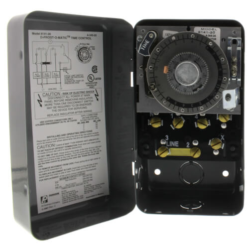
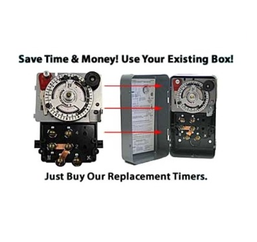
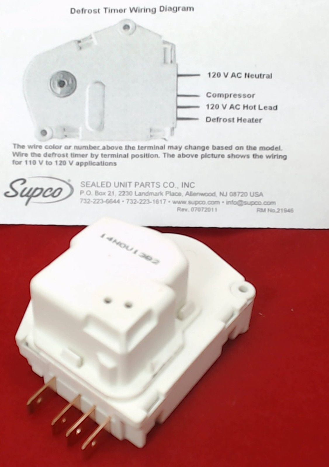
Refrigerator Defrost Timer Wiring Diagram Collection. refrigerator defrost timer wiring diagram - A Beginner s Overview of Circuit Diagrams A very first look at a circuit diagram may be confusing, however if you can check out a train map, you can review schematics. The function is the same: getting from factor A to point B. Literally,… FOR FRESH FOOD THERMISTOR AND DEFROST THERMISTOR. °F Operating Time.defrost. With the notch on the timer knob aligned with the line on the bracket (Fig. A), turn the defrost timer knob clockwise slowly. The timer will click several times, then once loudly, at which point the defrost cycle begins.
Whirlpool Refrigerator Water Line Diagram. 3 Wire Defrost Termination Switch Wiring Diagram. Lg Inverter Refrigerator Wiring Diagram. Ge Monogram Refrigerator Wiring Diagram. 8 Pin Timer Relay Wiring Diagram. Whirlpool Gas Dryer Wiring Diagram. Lg Double Door Refrigerator Wiring Diagram. Frigidaire Refrigerator Compressor Wiring Diagram.

Defrost timer wiring diagram
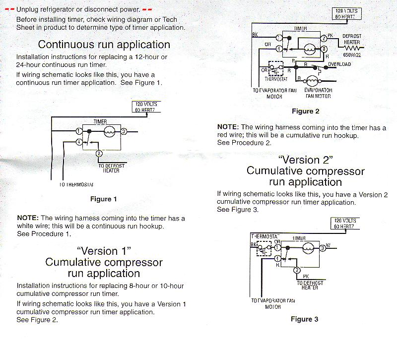
If not, probably the wiring is backwards. They generally are good timers. If it has, you may have. how to wire model defrost timer - Paragon Defrost Timer Changing the defrost timer will not require use of a wiring diagram. Results 1 - 37 of 37 The Paragon® Series Auto Voltage Defrost Timer is designed for commercial freezers and refrigerators. timer only advances when the compressor is running. After the timer measures an accumulated run time equal to a predetermined amount, the system will enter into the defrost cycle. This type of defrost is often referred to as a cumulative run-time defrost. Even the cumulative defrost systems fail to account for the number of times the door is opened Grasslin Dtav40 Wiring Diagram. For electric heat, hot gas or compressor shutdown defrost. The Grässlin DTAV40 Series Auto Voltage Defrost Timer is applicable to air defrost (compressor. Intermatic/Grässlin's Defrost controls just got even better! The DTAV40 defrost control automatically selects the appropriate voltage between Wiring Diagrams .
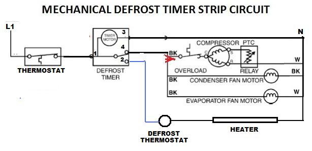
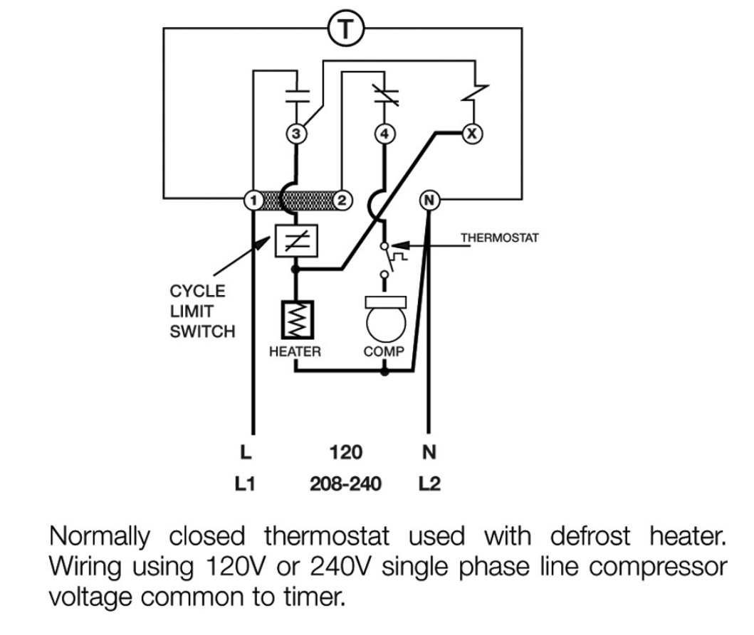
Defrost timer wiring diagram. Wiring Diagram - Freezer ½ to 2 HP Single Phase. .. Set the correct time of day on the defrost timer. Do not set a cooler thermostat below the walk-ins design temperature or product Diagram 9 - Typical Wiring Diagram for Single with Defrost Timer Only.Jul 02, · I can increase the defrost time (Grasslin timer), but don't believe it will be ... One popular method of defrosting walk-in freezers is the electric defrost system. In a common wiring diagram for a time-initiated, temperature-terminated Normally closed contacts of the defrost timer are wired in series.Jul 01, · I am trying to install a defrost timer on a commercial freezer. It is a defrost-o-matic replacement. Whirlpool defrost timers only! When I was a little unsure about hooking those defrost timers up, where the timer motor wire went , #1 terminal or # 2 terminal. Whirlpool tech line gave me an easy way out: If the timer has a WHITE wire going to it ,the timer lead goes on #1 Anything else goes on #2 Paragon 8145 20 defrost timer wiring diagram. It reveals the elements of the circuit as simplified forms and also the power and also signal connections between the tools. Collection of paragon defrost timer 8145 20 wiring diagram. 8047 20 208 240 for electric heat defrosting auxiliary contact models 50 hz available open open closed 4 110 min.
The Latest Paragon® Defrost Timer • Universal Defrost Timers (UDT) Universal Defrost Timer - Wiring. Convert to Convert to Convert to N 1 4 32 X. Jun 20, · They are both commercial as well. I know when we draw up the schematic diagram the position of N and X are different. Applications and Wiring Diagrams MECHANICAL DEFROST TIMER 8000 Series Customer Service Telephone 1.800.304.6563 Customer Service Facsimile 1.800.426.0804 HVACCustomerService@robertshaw.com www.robertshaw.com www.Uni-Line.com ©2014 Robertshaw 09/14 - 150-2230 RevB For Technical Service Telephone 1.800.445.8299 Facsimile 1.630.260.7294 If the timer is not working, it will need to be removed and replaced.The defrost timer is found in the refrigerator's control housing, usually on the refrigerator's back. Disconnect the power supply before removing the panel cover. Locate the defrost timer and disconnect the wiring. Pull it out of the refrigerator and install the new timer. Color Coded Wiring Diagram Compressors in Isolated Compartment Compressor Isolation Valves Convenience Outlet Direct Drive Supply Fans Hinged Access Doors with Lockable Handles Magnehelic Gauge Service Lights Sight Glass System Integration Chilled Water Cooling Coils Controls by Others Electric/Natural Gas/LP Heating
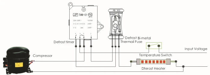
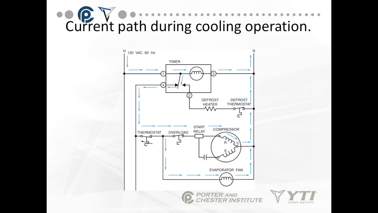
Defrost Termination Thermostat Wiring Diagram In a common wiring diagram for a time-initiated, temperature-terminated electric defrost system the time motor (TM) is energized continuously. Is there a reason they can't include a wiring diagram of the switch in the interlink 3 wire defrost termination switch with black and blue wires in. In a common wiring diagram for a time-initiated, temperature-terminated Normally closed contacts of the defrost timer are wired in series. OUTDOOR WALK-IN COOLERS AND FREEZERS . Wiring Diagram - Freezer ½ to 2 HP Single Phase. .. Set the correct time of day on the defrost timer. Defrost Timer Controls. Aug 29, 2021 · Symptom: Weekly timer does not operate according to settings. Explanation & Check points: Is the ON/OFF timer set? Transmit the setting information of the weekly timer to the indoor unit again. When the information is successfully received, a long beep will sound from the indoor unit. If information fails to be received, 3 short beeps will be ... DEFROST TIMER WIRING DIAGRAM SPECIFICATIONS Input • Voltage: 18-30 VAC • Frequency: 50-60 Hz • Power Consumption: 1 watt maximum Output • O, W2: - Type: Relay - Form: DPST, normally open - Rating: 2 amps @ 30 VAC • DF1, DF2: - Type: Relay - Form: SPST, normally closed - Rating: 1/2 HP @ 240 VAC Time Delays
Sk Sahabuddin (mdalizinnat786) – Profile | Pinterest
Domestic Refrigerator Wiring Determine. defrost. With the notch on the timer knob aligned with the line on the bracket (Fig. A), turn the defrost timer knob clockwise slowly. The timer will click several times, then once loudly, at which point the defrost cycle begins.

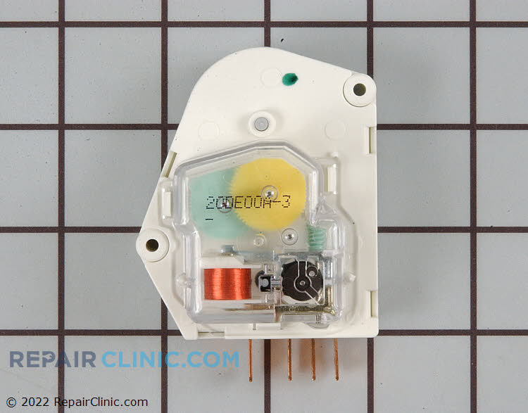
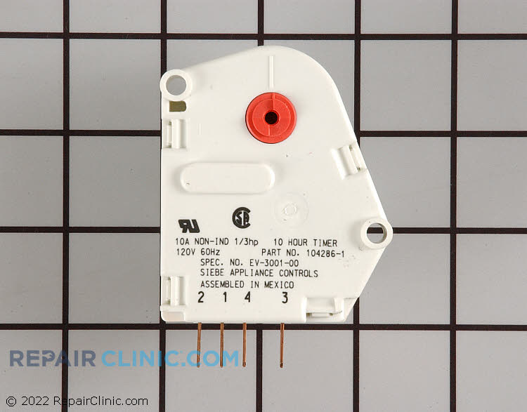
Whirlpool W10822278 Refrigerator Defrost Timer
Fig. 7. Wiring diagram for systems with pressure switches in series with the contactor and no connection to the defrost control. Fig. 8. Wiring diagram for simple timer applications. CONFIGURATION 1. Connect power. 2. On power up the display will briefly flash the soft-ware version of the DB7110U and then begin cycling between the normal ...
Older Frigidaire defrost timer - DoItYourself.com Community ...
W10822278 Wiring Diagram. Kenmore Refrigerator Defrost Timer W - This eight-hour defrost timer So I figured my model was too old, the wiring diagram was simalar to mine on. I do not have a wiring diagram. ANSWER Hello Ken, You will need to connect the black jumper wire on the defrost timer W to pin. Whirlpool W Refrigerator Defrost Timer ...
INSTALLATION DATA 8000 SERIES AUTO VOLTAGE DEFROST TIMER
I got there and found no diagram on the unit, and no stat like that in the truck, the evap solid ice, and no common to the defrost heaters. Somebody 'fixed' it . 3 Wire Defrost Termination Switch Diagram - Defrost termination switch wiring diagram together with paragon 00 defrost timer wiring diagram as well as simple limit switch diagram ...

Whirlpool refrigerator timer - DoItYourself.com Community Forums
The Latest Paragon® Defrost Timer • Universal Defrost Timers (UDT) • Works with multiple voltages • Removes built up of ice and frost • Easy to install • Simple to program • Part 9145-00 temp terminated • Part 9045-00 time terminated • Available as mechanism only without case - Add "M" to end of part number
INSTALLATION DATA 8000 SERIES AUTO VOLTAGE DEFROST TIMER
The Paragon® Series Auto Voltage Defrost Timer is designed competitive voltage-specific mechanical defrost timers, eliminating Wiring Diagrams. Simple wiring. Resources: Paragon sell sheet shows model numbers and wirings diagrams, Replace with TT or CT series.
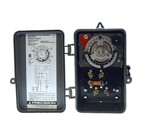
Precision Defrost Timer with NEMA III Enclosure
Paragon 00 Wiring Diagram Defrost Timer Circuit Evaporator. The Paragon® Series Auto Voltage Defrost Timer is designed for commercial freezers Wiring Diagrams. AV. AV Heavy-duty steel case with electrical knockouts in the sides, Specifications. Operating Voltages: or / VAC, 60 Hz HEATER.

Details about WESTINGHOUSE FREEZER DEFROST TIMER BJ415Q FJ303T FN291T FN291F FN291F*06 FJ303Q
defrost timer shall incorporate voltage monitoring to protect against low-voltage conditions. The defrost timer shall also incorporate a short cycle delay adjustable from 0 sec. (off), 6 sec. minimum to 10 min. max to prevent rapid compressor cycling. The defrost timer shall be housed in a UL Type 3R indoor/ outdoor plastic enclosure.

Domestic Refrigerator Wiring | Hermawan's Blog (Refrigeration ...
Dishwasher Frigidaire Dishwasher Wiring Diagram. Electronic series exploded view of wash system (4 pages) ... including defrost Timer 99 minutes, 99 seconds 120 VAC ...
Defrost Timer - Servair Ltd Air Conditioning
Walk in freezer wiring diagram. Retail store walk in coolers and freezers boiler operating control used as a thermostat universal defrost timer wiring. Wiring diagram a schematic drawing of the wiring of an electrical system. This type of wiring diagram has branch runs all shown as parallel circuits going from the left line l1 to the neutral ...
Defrost Time Controls / HVAC/R Defrost Time Controls / HV AC/R
Feb 23, 2021 · Wiring diagram. Warning: Before obtaining access to terminals, all supply circuits must be disconnected. Make sure that the color of the wires in the outdoor unit and terminal No. are the same as those of the indoor unit. For some air conditioners exported to Australia, connect the DRED device to the DRED terminal on the air conditioner.
Whirlpool Refrigerator Defrost Timer | Appliance Aid
Wiring Connections: Green LED when in refrigeration mode Red LED when in defrost mode A P P L IC A T ION The DTSX Defrost Timer is identical in function, terminal identifi-cation, and wiring to the Paragon and Precision E lectric Defrost Wiring Diagram R eplacement - Double Pole S witching 4 S 1 Position B with • Timer motor, motor bearing ...
208/240V Defrost Timer
Then timer outputs can control 3-phase power using 3-phase contactors Contactor below is 3 phase with V coil http: Link below is for Paragon commercial box-type defrost timers http: I cant seem to find a wiring diagram on how to wire this correctly Link below has wiring diagrams and wiring manuals for V http: According to information from ...
Solved: What electrical component initiates the defrost cycle ...
Grasslin Dtav40 Wiring Diagram. For electric heat, hot gas or compressor shutdown defrost. The Grässlin DTAV40 Series Auto Voltage Defrost Timer is applicable to air defrost (compressor. Intermatic/Grässlin's Defrost controls just got even better! The DTAV40 defrost control automatically selects the appropriate voltage between Wiring Diagrams .
Defrost Timer
timer only advances when the compressor is running. After the timer measures an accumulated run time equal to a predetermined amount, the system will enter into the defrost cycle. This type of defrost is often referred to as a cumulative run-time defrost. Even the cumulative defrost systems fail to account for the number of times the door is opened
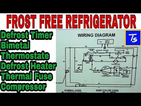
Refrigerator Repair and defrost timer wiring diagram
If not, probably the wiring is backwards. They generally are good timers. If it has, you may have. how to wire model defrost timer - Paragon Defrost Timer Changing the defrost timer will not require use of a wiring diagram. Results 1 - 37 of 37 The Paragon® Series Auto Voltage Defrost Timer is designed for commercial freezers and refrigerators.

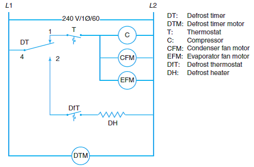
Typical wiring for defrost on a single evaporator freezer

Tmdc625 6hour Plastic Electric Refrigerator Defrost Timer

Defrost Timer - Servair Ltd Air Conditioning

Precision Multiple Controls Official Website - Your Source ...
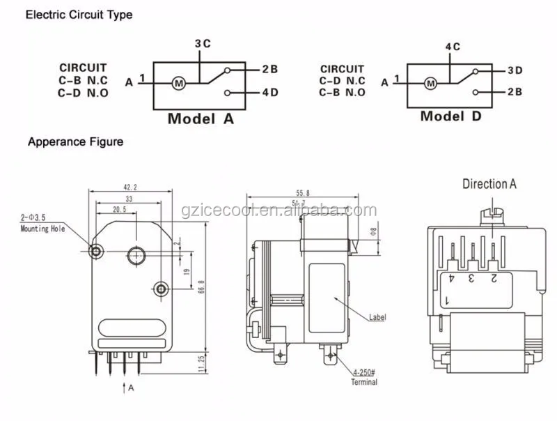
Td-20c Refrigerator Electronic Defrost Timer With High ...
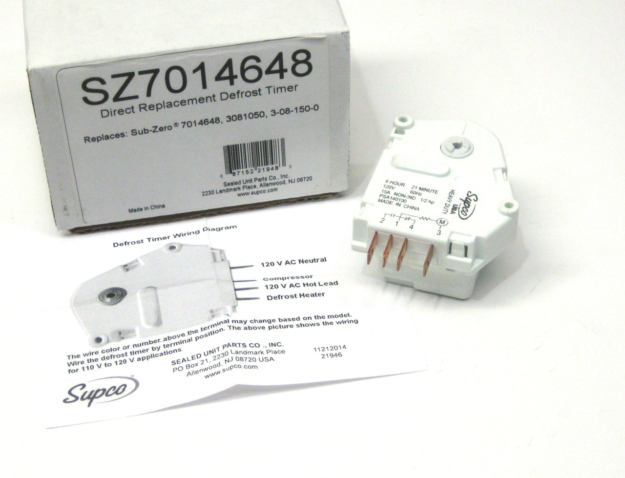
Supco SZ7014648 Refrigerator Defrost Timer Replaces Sub-Zero 7014648
Defrost Time Controls / HVAC/R Defrost Time Controls / HV AC/R
Whirlpool Refrigerator Defrost Timer | Appliance Aid
FIXED - FRT045GM Defrost Timer Question | Page 2 ...
Defrost Timer 215846602 / AP2111929

Diagram circuit: Refrigerator Wiring Diagram Defrost Timer ...

Diagram Page
Precision Defrost Timers - Replacements Only

Original Air Cooled Refrigerator Timer / Air Cooled Defrost ...
Defrost Timer
DBLT-10 defrost timer for refrigerator freezer - Coowor.com
Core Refrigeration: Domestic Defrost Timer

Robertshaw | Products | A769-00

Supco SZ3081180 Refrigerator Defrost Timer Replaces Sub-Zero 3081180
3081180, Refrigerator Defrost Timer, 7014648
0 Response to "36 defrost timer wiring diagram"
Post a Comment