38 air ride wiring diagram
PDF Installation Guide & Operation Manual - Ridetech Mounting the Air Tank • The air tank can be mounted anywhere on the vehicle in any position, So long as the sensor is not pointed down. • There is an 1/8" port in the tank that will accept the tank pressure sensor. Mounting the RidePro Air Valves • The valves, like the compressor, are sealed and can be mounted in the same locations. Wiring Diagrams & Installation Docs - Skully Customs Link to Download Install Instructions:Download Here Link to Download Wiring Diagrams:Download Here Link to Download Tank Wiring and Pneumatic Diagrams:Download Here Standard Install with Toggle Switch: _____Standard Install with Handlebar Switch: _____ Standard Inst ... Front and Rear Air Ride . Search; Join our mailing list. Want to hear the ...
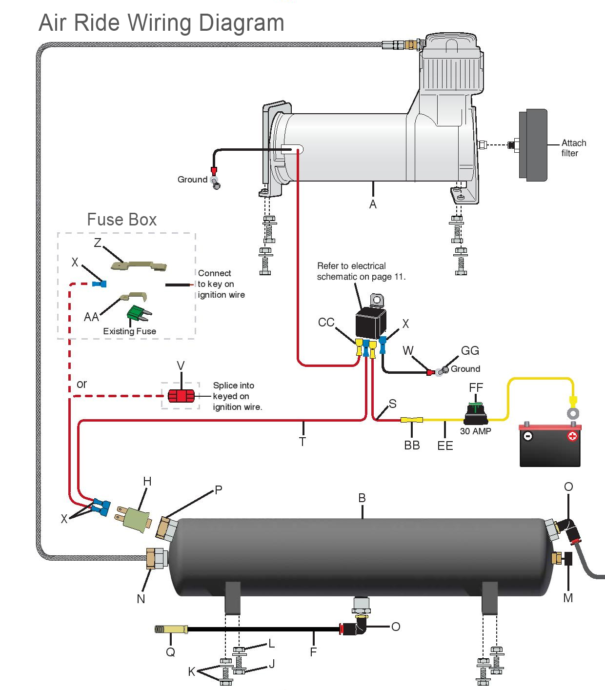
PDF Air Compressor/Air Control INSTALLATION ... - Ride Well Corp 1220026 Air Compressor Kit Figure 2. Wiring Diagram for 1220026 A/CPSR Kit 1220026 A/CPSR Kit - WiRing DiAgRAM/SeRviCe PARtS DWG NO. QTY PART NO. ITEM DESCRIPTION 1 1 1230236 PACBRAKE AIR COMPRESSOR, 3/4 HP 12V 42A 2 1 1420192 BUSSMANN POWER MODULE RELAY (PRM), 12V 70A 3 1 1420198 METRI-PACK (M-P) 800 FEMALE TERMINAL, 12-14 GAUGE
Air ride wiring diagram
Wiring Diagram For Air Ride On Motorcycle With A Tank ... Wiring Diagram For Air Ride On Motorcycle With A Tank. Print the wiring diagram off plus use highlighters to trace the signal. When you make use of your finger or perhaps the actual circuit with your eyes, it is easy to mistrace the circuit. 1 trick that We 2 to printing a similar wiring plan off twice. SOLVED: Air ride suspension control diagram - Fixya There is a lot involved in is air ride suspension system ! A 60a Fuse in the under hood fuse block Marked VSES / ECAS .This is the power for the compressor . There is a air suspension control module , Ride height switch , Fuse in the I / P fuse block 4 WD 15a supply's B+ to ride height switch . Wiring diagrams for air ride systems, air springs WIRING DIAGRAMS FOR AIR RIDE SYSTEMS Pdf (wiring_diagrams_2050.pdf) Download. WIRING DIAGRAMS FOR AIR RIDE SYSTEMS PDF. As this is a free service it receives an overwhelming amount of requests and may take up to a week or longer for a response. Get the scoop on the MAP sensor from an electronic point of view and towards reading wiring diagrams.
Air ride wiring diagram. Air Ride Switch Wiring Diagram - justussocializing.org Wiring Diagrams December 11, 2021 20:07. Air Ride Switch Wiring Diagram - One of the most hard automotive repair tasks that a mechanic or repair shop can put up with is the wiring, or rewiring of a car's electrical system. The misery in reality is that every car is different. once frustrating to remove, replace or fix the wiring in an ... Air Ride Suspension Wiring Diagram Air Ride Suspension Wiring Diagram- One of the most hard automotive fix tasks that a mechanic or fix shop can take is the wiring, or rewiring of a car's electrical system.The misery in point of fact is that every car is different. later than exasperating to remove, replace or fix the wiring in an automobile, having an accurate and detailed Air Ride Suspension Wiring Diagram is vital to the ... Air Ride Wiring Diagram Collection Air Ride Wiring Diagram. Air Ride Wiring Diagram from jleiwig.20megsfree.com. Print the wiring diagram off and use highlighters in order to trace the signal. When you employ your finger or stick to the circuit together with your eyes, it's easy to mistrace the circuit. 1 trick that I 2 to printing the same wiring plan off twice. Air Ride Compressor Wiring Diagram - Wiring Sample The wiring diagram identifies the fan motor and compressor s wire colors and functions. Mounting the Air Tank The air tank can be mounted anywhere on the vehicle in any position so long as the sensor is not pointed down. The yellow wire on the relay will go to the Red wire on the compressor.
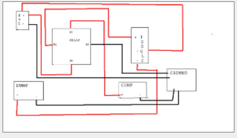
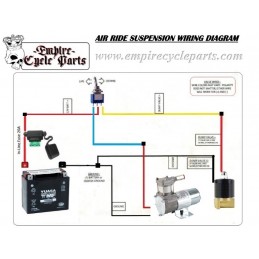
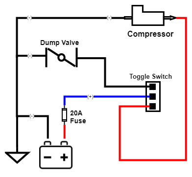
PDF ezairride.com EZ Air Ride Dual 444C Wiring Diagram To Tank 12V 40A Relay Do not Use Red Wire To Tank 12V 40A Relay Do not Use Red Wire Pressure Switch TO Keyed power Source (either prong) Fuse Battery Relays— Relays help to increase the life expectancy of pressure switches by protecting them from the high-amp draw of the [How-to]:Complete Air-Ride Plumbing/Wiring | S-10 Forum Here are a couple examples on how to do this... First, most tanks we use have 1/2" ports on them. That port will flow a lot of air. You can put two viair compressors on one port. A 480 only puts out about 1/2 a cfm at high pressure. 1/2 + 1/2 = 1. A 1/2" port will easily flow more than 1 cfm. Ridetech Valve Wiring Diagram Wiring harness - Control panel to valve. 3.Nov 26, · The RidePRO from Ridetech is the most reliable volt air valve control system on the market today! The RidePRO assembly can be placed anywhere in the vehicle while the switches and gauges can be mounted on the console, in the dash, the glove box, etc. Ridetech Pro Valve Wiring Diagram Air Ride Technologies • 1 . This guide covers installation of all RidePRO e2®, LevelPRO™ and AirPod™ systems. . the Big Red valves an adapter harness.Wiring the compressor, ECU, and valve block was as easy as following the directions and wiring diagram, as each has a separate harness.
DIRTY AIR USA: Switches & Wiring DIRTY AIR Reverse-Polarity relay pack for 3-wire switch to control MRI center stand $49.99. DIRTY AIR Safety Valve Toggle Switch - BARE $24.99. Toggle Switch Waterproof Boot $4.99. Wired Toggle Switch - Momentary $19.99. Fused Wire Holder $4.99. RELAY WIRE HARNESS $5.99. 2-Way Manual Toggle Valve $69.99. DIRTY AIR Front+Rear Wiring Kit $44.99. Buick Lesabre Air Ride Automatic Level Control Wiring Diagram Acces PDF Buick Lesabre Air Ride Automatic Level Control Wiring Diagram Skylark 455 Stage 1 N25 exhaust Gran Sport Ram Air 1972 Find the best used 2005 Buick LeSabre near you. Every used car for sale comes with a free CARFAX Report. We have 40 2005 Buick LeSabre vehicles for sale that are reported accident free, 8 1-Owner cars, and 54 personal ... PDF Installation and operating instructions - AirBagIt i. Connect each wire to its corresponding valve as shown on the Non-PnP Wiring Schematic. ii. If you have purchased this Smart-Ride controller with one of Airbagit.com's Air Engine valve assemblies, or Air Force then the Valve Loom will plug right into the Air Engine's white 9 pin plug. See Air Engine Wiring Schematic. PDF Installation Guide & Operation Manual - Ridetech 1 Installation Guide & Operation Manual RideTech 350 S. St. Charles St. •Jasper, IN 47546 • 812-481-4969 TM
05 Expy air suspension line diagram - Ford Truck Enthusiasts ...
EZ Air Ride Installation Instructions Here you will find installation, plumbing and wiring instructions for all of our EZ Air Ride kits. If you need further help, you can find more info below. "Do it once, do it right! Don't do it again." ™. (916) 337-2231. info@ezairride.com.
Arnott air ride wiring... - Harley Davidson Forums
77 Awesome Air Ride Relay Wiring Diagram | Air ride ... 77 Awesome Air Ride Relay Wiring Diagram- A manage relay is used in the automotive industry to restrict and amend the flow of electricity to various electrical parts inside the automobile. They allow a small circuit to govern a future flow circuit using an electromagnet to govern the flow of electricity inside the circuit.
Manual Air Ride Management Kit Wiring / Valve / Pneumatic ...
Inspirational Air Ride Switch Box Wiring Diagram | Air ... 77 Awesome Air Ride Relay Wiring Diagram- A manage relay is used in the automotive industry to restrict and amend the flow of electricity to various electrical parts inside the automobile. They allow a small circuit to govern a future flow circuit using an electromagnet to govern the flow of electricity inside the circuit.
Harley Bagger Front Air Ride Kit For 2014 - 2021
Yukon xl air ride wiring diagram - Fixya SOURCE: 2004 yukon xl denali self-leveling rear air shocks. There's a lever that connects the driver-side rear shock to the Automatic Level Control module (the air compressor and the ride-height sensor). Disconnect the lever from the shock and rotate it up and hold it. The compressor should kick in when you hold in place after a few seconds.
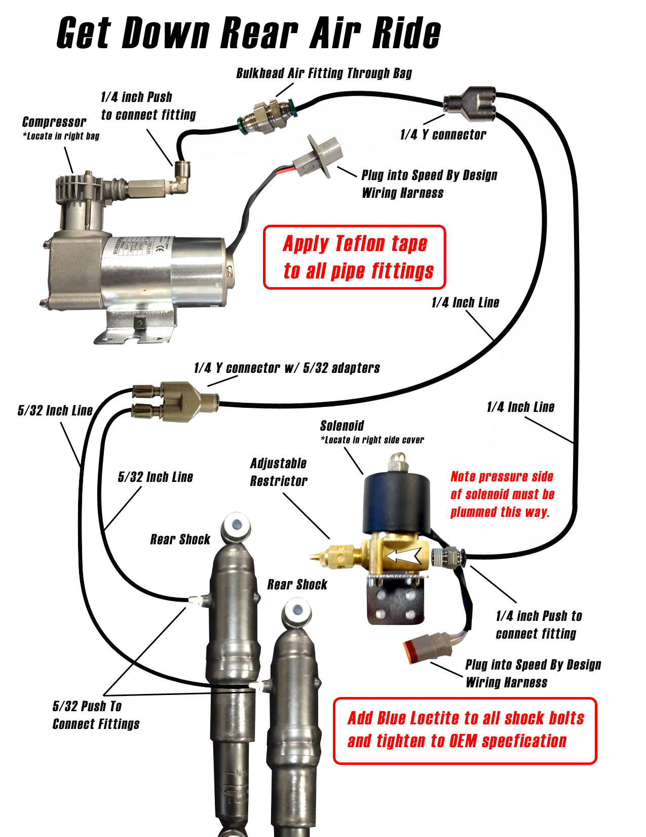
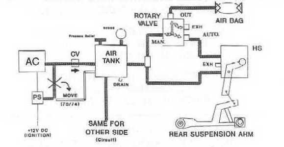
Harley Fast Up Air Ride Rear Kit & Diagram | Speed By Design
Manual Air Ride Management Kit Wiring / Valve / Pneumatic ... Air Ride Manual 4-Valve Management System Wiring Diagram for most Manual Operated Air Ride Systems These wiring diagrams cover all "C" Model Viair Compressors as Included with our Manual Air Ride Management Kits Use the Following Diagram for Twin Compressor Setups We recommend all items are installed by a qualified individual (s).

Wiring Diagrams & Installation Docs – Skully Customs
Air Ride Suspension Wiring Diagram - easywiring Air ride suspension wiring diagram. If you need further help you can find more info below. Ez air ride dual 444c wiring diagram to tank 12v 40a relay do not use red wire to tank 12v 40a relay do not use red wire pressure switch to keyed power source either prong fuse battery relays relays help to increase the life expectancy of pressure ...

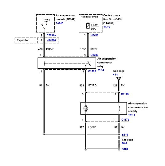
2000 ford expedition, air suspension wiring digram needed.
PDF Kelderman Performance Suspension Parts Installation Manual Power and Height sensor wiring . Power Supply . As shown in the diagram, the system power is supplied with a fuse holder, 60 Amp fuse, and wires designed to be routed directly to the battery. Sensor Wiring . The sensor wires are labeled for driver side and curb side angle sensors. The driver FRONT wires are
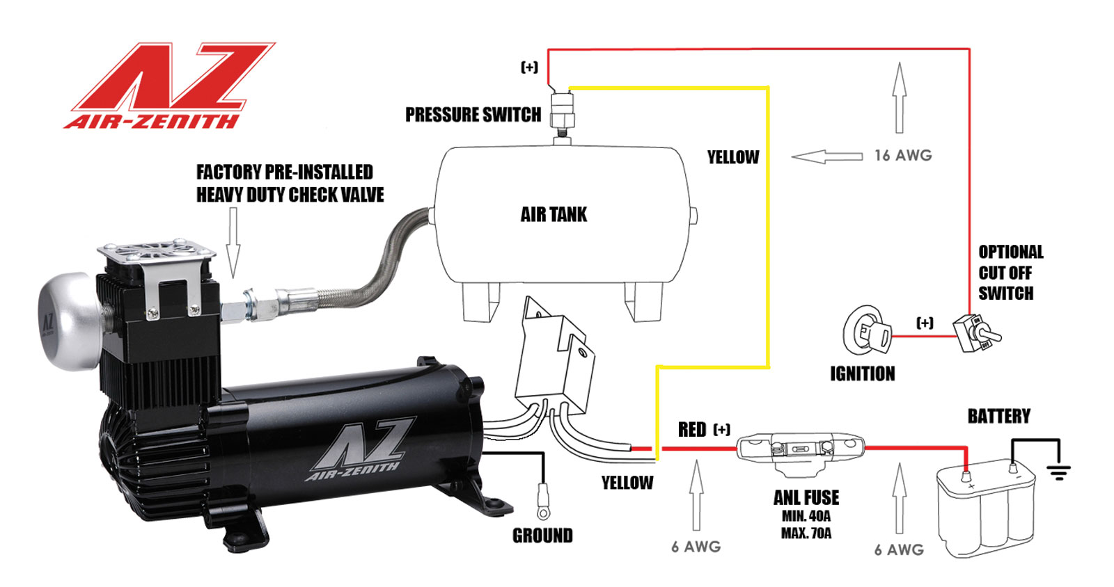
Tech Support – Air Zenith
Air Ride Relay Wiring Diagram - easywiring Wiring diagram warning. Browse categories answer questions. Here you will find installation plumbing and wiring instructions for all of our ez air ride kits. Connect the black wires pin 1 pin 3 to ground. Connect the lcd controller to the relay control box. 1963 1972 chevy c10 platinum ez air ride suspension kit.

AVS 250 PSI 1/2" VALVE WITH MOUNTING BRACKET
Diagrams - Air Ride, Hydraulics, Wire Wheels | Cool Cars ... Air Ride; Hijacker Hydraulics; CCE Hydraulics; Wire Wheels; Diagrams; Videos; Contact Us; Returns & Refunds; Search for: Home / Diagrams. Diagrams onething 2021-12-12T19:34:08-05:00. AIR RIDE DIAGRAMS. HYDRAULICS DIAGRAMS. Search products. Product categories. Online Specials (22) New Products (37) CCE APPAREL (14) Hijacker Hydraulics (265) Air ...

How to test ALC Relay GMC Air Ride Suspension
Wiring diagrams for air ride systems, air springs WIRING DIAGRAMS FOR AIR RIDE SYSTEMS Pdf (wiring_diagrams_2050.pdf) Download. WIRING DIAGRAMS FOR AIR RIDE SYSTEMS PDF. As this is a free service it receives an overwhelming amount of requests and may take up to a week or longer for a response. Get the scoop on the MAP sensor from an electronic point of view and towards reading wiring diagrams.

1958-1964 Chevy Impala Deluxe EZ Air Ride Suspension Kit
SOLVED: Air ride suspension control diagram - Fixya There is a lot involved in is air ride suspension system ! A 60a Fuse in the under hood fuse block Marked VSES / ECAS .This is the power for the compressor . There is a air suspension control module , Ride height switch , Fuse in the I / P fuse block 4 WD 15a supply's B+ to ride height switch .
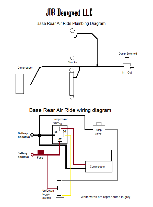
Frequently Asked Questions - JNR Designed
Wiring Diagram For Air Ride On Motorcycle With A Tank ... Wiring Diagram For Air Ride On Motorcycle With A Tank. Print the wiring diagram off plus use highlighters to trace the signal. When you make use of your finger or perhaps the actual circuit with your eyes, it is easy to mistrace the circuit. 1 trick that We 2 to printing a similar wiring plan off twice.
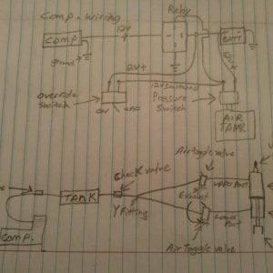
Rudimentary sketch of wiring and airline diagram. | Honda ...

Kewlmetal Air Ride System Installation

Compressor Installation Instructions~ AirBagIt.com
Wiring Diagrams & Installation Docs – Skully Customs
e61 2007 pre LCI self levelling suspension problem ...

View Three Phase 3 Phase Air Compressor Pressure Switch ...

Wiring Diagrams & Installation Docs – Skully Customs

Wiring for rear airbag set up | The H.A.M.B.
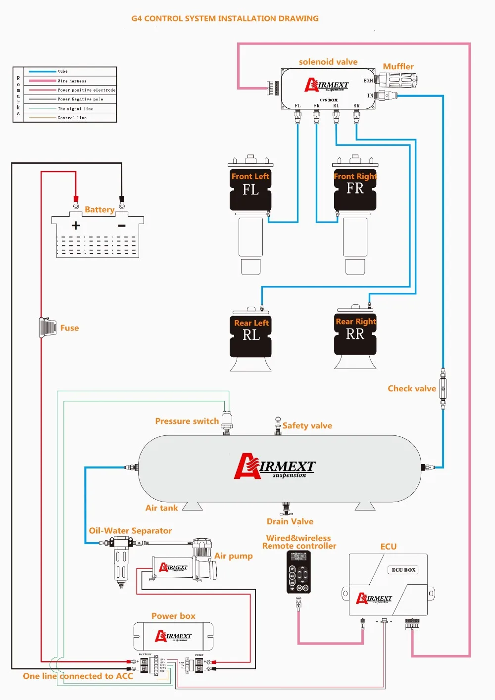
AIRMEXT top grade luftfederung FULL KIT/ganze kits/AIRRIDE ...
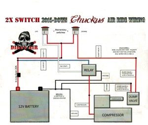
Dirty Air Suspension – ChuckusLife

Where is the air ride compressor relay located on a 2003 ...

Universal pneumatic shock absorber 1/4" 4 corner solenoid ...

Air Suspension Inoperative – Check these first – Rustyautos.com

DIGIFIZmini - Oil & Air Ride Pressure

Air ride causing battery drain - The 1947 - Present Chevrolet ...
Custom Aftermarket Air Ride Suspension Kit Installation ...

A Body Platinum EZ Air Ride Suspension Kit
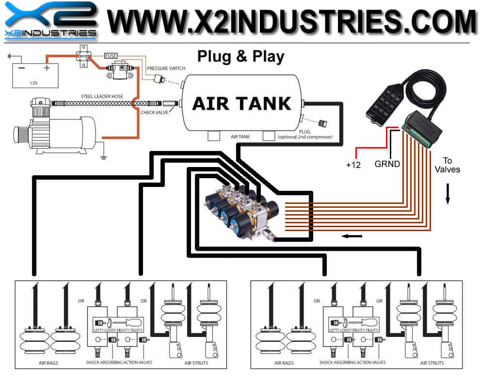
Air Compressor Kit Mounting Guide Air Compressor – Wire Diagram
Air Suspension System
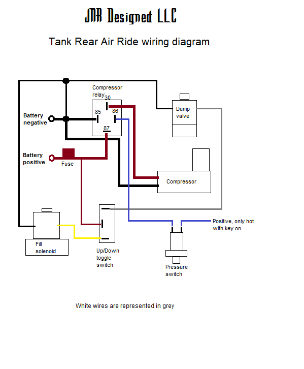
Frequently Asked Questions - JNR Designed

17+ Printable Wiring Diagram 2005 Lincoln Town Car - Car ...
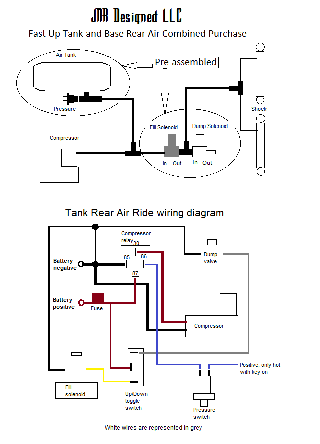
Add-on Fast Up Rear Air Tank kits - JNR Designed
RAS (rear air suspension) switch question: - Toyota 4Runner ...

ELECTRONIC SUSPENSION – Porsche Cayenne S 2010 – SYSTEM ...
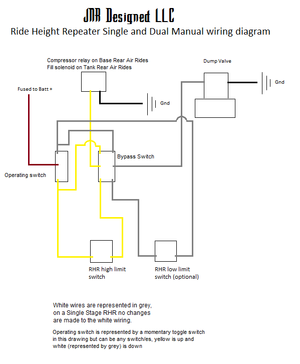
RHR wiring diagram - JNR Designed

DIY Air ride wiring help?? - Harley Davidson Forums
0 Response to "38 air ride wiring diagram"
Post a Comment