38 radar system block diagram
The radar pulse width is programmable between 5 and 100 microseconds. The antenna's slotted waveguide radiators are capable of operating in dual polarization mode and the antenna has a peak power consumption of 4,368 Watts. C-SAR operates at a pulse repetition frequency of 1000 to 3000 Hz and a sampling rate of 300 Mhz. SAR Block Diagram CW and Frequency Modulated Radar: Doppler Effect, CW Radar – Block Diagram, Isolation between Transmitter and Receiver, Non-zero IF Receiver, ...156 pages
Ample teaching and self-study help is incorporated throughout, including: * Numerous worked-out examples illustrating radar theory * Many end-of-chapter problems * Hundreds of illustrations, including system block diagrams, demonstrating how radar functions are achieved * Appended review material and useful mathematical formulas * An extensive ...
Radar system block diagram
radar theory * Many end-of-chapter problems * Hundreds of illustrations, including system block diagrams, demonstrating how radar functions are achieved * Appended review material and useful mathematical formulas * An extensive bibliography and references. Automotive Radar Systems - 9 images - , extensible dsp for autonomous driving, ... Radar System Block Diagram. Car Radar Detector. Radar Frequency Bands. Automotive Radar Antenna. Radar System Plans. Police Car Radar Systems. Gallery of Automotive Radar Systems. Figure 1 System block diagram. Figure 2 RI&S transmitter. In November 2019, GBO shipped the PFH to RI&S for transmitter installation. The Peltier coolers were removed and replaced with a simple ethylene/glycol heat exchanger. The system block diagram is shown in Figure 1. The blocks in the light gray background were integrated into the PFH.
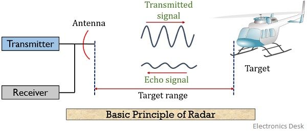
Radar system block diagram. Basic Radar System Block Diagram consists of a transmitter and a receiver, each connected to a directional antenna. The transmitter is capable of sending ...9 pages examples illustrating radar theory * Many end-of-chapter problems * Hundreds of illustrations, including system block diagrams, demonstrating how radar functions are achieved * Appended review material and useful mathematical formulas * An extensive bibliography and references. *An Instructor's Manual presenting detailed solutions to all the ... the text is complemented with flowcharts and system block diagrams to aid in readers' comprehension. Digital Signal Processing Techniques and Applications in Radar Image Processing serves as an ideal textbook for graduate students and Radar Block Diagram. Here are a number of highest rated Radar Block Diagram pictures upon internet. We identified it from honorable source. Its submitted by management in the best field. We put up with this kind of Radar Block Diagram graphic could possibly be the most trending subject like we part it in google pro or facebook.
robotics. applications. Our innovative analog and embedded technologies enable engineers to develop the most intelligent and sophisticated robot systems of tomorrow. Navigate new system block diagrams and quickly find fully tested reference designs and products for your next industrial, logistics or service robot design. Industrial robots. The simpli fi ed system block diagram for the range and speed sensing is shown in Figure 2A , where a frequency-sweeping signal (chirp signal) is ampli fi ed and transmitted through the power ... Transmitter and Receiver Block Diagram- Radar Radar Transmitter Radar TX Calculation Pin = 15dBm = 31.62mW Pout = 28.04dBm = 636.76mW Pdc = 1500mw + 6750mw + 4125mw = 12375mW PAE (%) = 4.9% Gt = 20dBi EIRP = Pt + Gt = 28.04dBm + 20dBi = 48.04dBm MDS = N0 = KTB = -113.86dBm = 4.1*10-9 mW fo = 77GHz 𝜎 = 1m2 𝜆 = 0.0392m the radar community as an expert in the technical area that his chap ter addresses, and each had already authored and published a major book on his subject. Several other contributing authors, including Dr. Bodnar, Mr. Bruder, Mr. Corriher, Dr. Reedy, Dr. Trebits, and Mr.
problems * Hundreds of illustrations, including system block diagrams, demonstrating how radar functions are achieved * Appended review material and useful mathematical formulas * An extensive bibliography and references. *An Instructor's Bookmark File PDF Solution Manual Introduction To Radar Systems Skolnik Introduction to System Dynamics Electronic navigation, although still relatively new, is becoming increasingly more common, particularly on commercial vessels. This handbook offers a wealth of detailed information about how MAGNETIC FIELD SYSTEM. Magnetic field system is a static part of DC motor. It is also known as by the name of yoke and stator. It carry the magnetic flux and also protect the internal part of dc motor from dust , moisture ,water etc; It hold the pole core and pole shoes; The field Winding is constructed on the pole core; 2. block diagram of a typical radar system download. Basic Radar Block Diagram. Here are a number of highest rated Basic Radar Block Diagram pictures upon internet. We identified it from obedient source. Its submitted by direction in the best field. We put up with this kind of Basic Radar Block Diagram graphic could possibly be the most trending ...
RADAR: Principle, Applications, Transmission and reception of ...
processing stages in 3D and/or cross-sectional views. Additionally, the text is complemented with flowcharts and system block diagrams to aid in readers' comprehension. Digital Signal Processing Techniques and Applications in Radar Image Processing serves as an ideal textbook for graduate students and practicing engineers who wish to gain firsthand
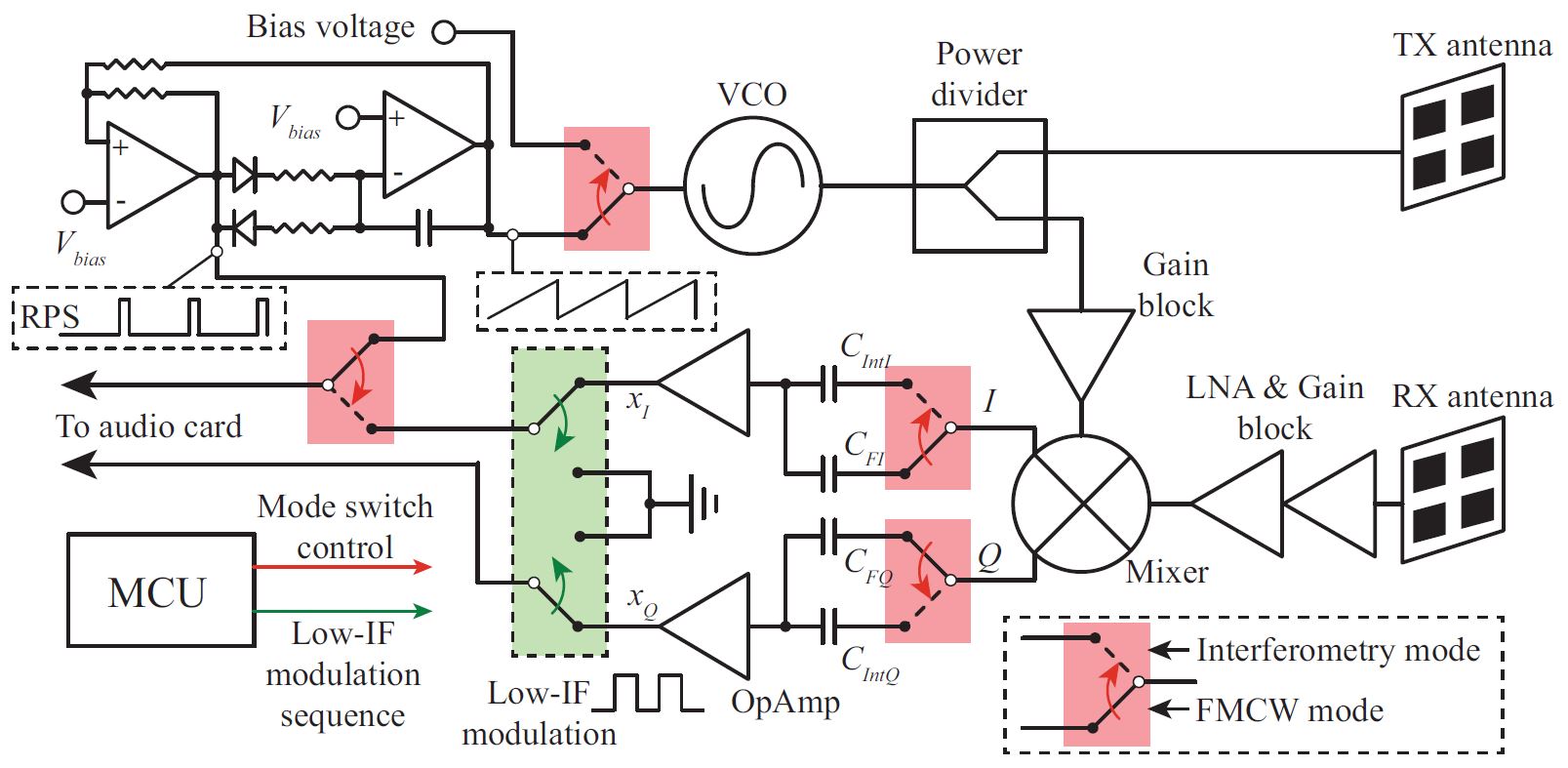
C-Band Portable Multi-Mode Radar – Z. PENG
That number is entered into the transponder and corresponds with that particular aircraft's identification and flight plan in the ATC computer system. ATC relies on two radar systems: primary ...
What is Radar System? Definition, Basic Principle, Block ...
Figure 2: FMCW system - block diagram. A series of FMCW chirps is fed to the Tx antenna and the mixer at the receiver. After mixing the transmitted signal and the received signals reflected from the target, the beat signal is generated, which has a frequency proportional to the delay corresponding to the distance between the radar and the target.

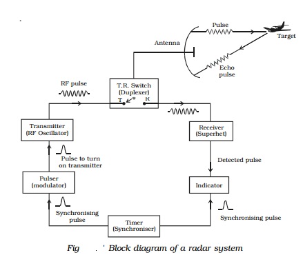
Pulse Radar system block diagram
Hundreds of illustrations, including system block diagrams, demonstrating how radar functions are achieved * Appended review material and useful mathematical formulas * An extensive bibliography and references. *An Instructor's Manual presenting detailed solutions to all the problems in the book is available from the Wiley editorial department.

MicroASAR - eoPortal Directory - Airborne Sensors
Numerous worked-out examples illustrating radar theory * Many end-of-chapter problems * Hundreds of illustrations, including system block diagrams, demonstrating how radar functions are achieved * Appended review material and useful mathematical formulas * An extensive bibliography and references. *An Instructor's Manual presenting detailed
Advantages of CW Radar | disadvantages of CW Radar
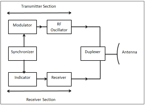
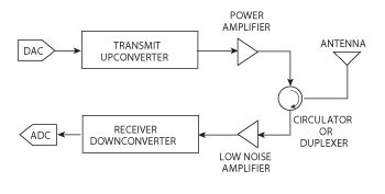
TOPIC #3 (Radar Block Diagram) The most elementary functions of a radar system start with. Generating a Waveform. Feeding it into the transmitter to amplify it. Transmit the signal through an array. As the signal propagates, it experiences different environmental effects, like rain and fog. It hits the target and comes back to the radar.

Figure 2 from Lesson 4. Track Radar Systems | Semantic Scholar
the Non-SpecialistIntroduction to Radar AnalysisIntroduction to Radar SystemsA Family of Solutions of Certain Nonautonomous Differential Equations by Series of Exponential FunctionsMulti-Carrier Systems & Solutions 2009Monopulse RadarRadar System Analysis and ModelingSmall and Short-Range Radar SystemsDesign
What is Radar System? Definition, Basic Principle, Block ...
We give a positive response this kind of Software Defined Radio Block Diagram graphic could possibly be the most trending subject in imitation of we share it in google plus or facebook. We attempt to introduced in this posting back this may be one of wonderful suggestion for any Software Defined Radio Block Diagram options.

Basic block diagram of a radar system | Download Scientific ...
Propulsion System EDM Propulsion System Block Diagram & Schematic - Credit: Thales Alenia . EDM Tank Assemblies - Photo: Thales Alenia. The Schiaparelli lander employs a propulsive landing system that comes into action after the Surface Platform separates from the Back Shell containing the parachute.
RADAR | Electronic tutorial | Mepits | Mepits
Continuous Wave Radar. Here are a number of highest rated Continuous Wave Radar pictures on internet. We identified it from well-behaved source. Its submitted by organization in the best field. We understand this nice of Continuous Wave Radar graphic could possibly be the most trending subject like we share it in google lead or facebook.
Build A Phased-Array Radar In Your Garage That Sees Through ...
A reliability block diagram (RBD) is a drawing and calculation tool used to model complex systems. An RBD is a series of images (blocks) representing portions of a system. Once the images (blocks) A computer can process data, pictures, sound and graphics. They can solve highly complicated problems quickly and accurately.

Draw block diagram of basic radar system and describe its ...
including: * Numerous worked-out examples illustrating radar theory * Many end-of-chapter problems * Hundreds of illustrations, including system block diagrams, demonstrating how radar functions are achieved * Appended review material and useful mathematical formulas * An extensive bibliography and references. *An
Keysight Technologies UK - New facelift for radar – but the ...
Aesa Radar System. Here are a number of highest rated Aesa Radar System pictures on internet. We identified it from honorable source. Its submitted by management in the best field. We assume this nice of Aesa Radar System graphic could possibly be the most trending subject taking into consideration we ration it in google gain or facebook.

Explain the principle and working of RADAR with neat block ...
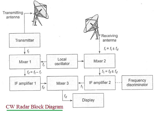
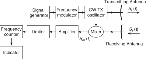
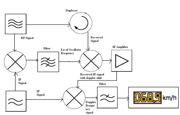
Draw the block diagram and explain the operation of a CW Doppler radar using an intermediate frequency in the receiver. How have the d_rawbacks of the basic CW radar been overcome? With the aid of a block diagram explain the operation of an FM. CW radar altimeter.
Basic Radar System Block Diagram: Fundamentals of Basic Radar ...
Figure 1 System block diagram. Figure 2 RI&S transmitter. In November 2019, GBO shipped the PFH to RI&S for transmitter installation. The Peltier coolers were removed and replaced with a simple ethylene/glycol heat exchanger. The system block diagram is shown in Figure 1. The blocks in the light gray background were integrated into the PFH.
/Year_5/ELC-544E-Radar%20Systems%20and%20Satellite/RADAR/Images/Radar%20Block_Diagram(1).GIF)
Introduction to Radar Systems
Automotive Radar Systems - 9 images - , extensible dsp for autonomous driving, ... Radar System Block Diagram. Car Radar Detector. Radar Frequency Bands. Automotive Radar Antenna. Radar System Plans. Police Car Radar Systems. Gallery of Automotive Radar Systems.
Block diagram of an FMCW radar system. | Download Scientific ...
radar theory * Many end-of-chapter problems * Hundreds of illustrations, including system block diagrams, demonstrating how radar functions are achieved * Appended review material and useful mathematical formulas * An extensive bibliography and references.

Basic block diagram of a radar system | Download Scientific ...

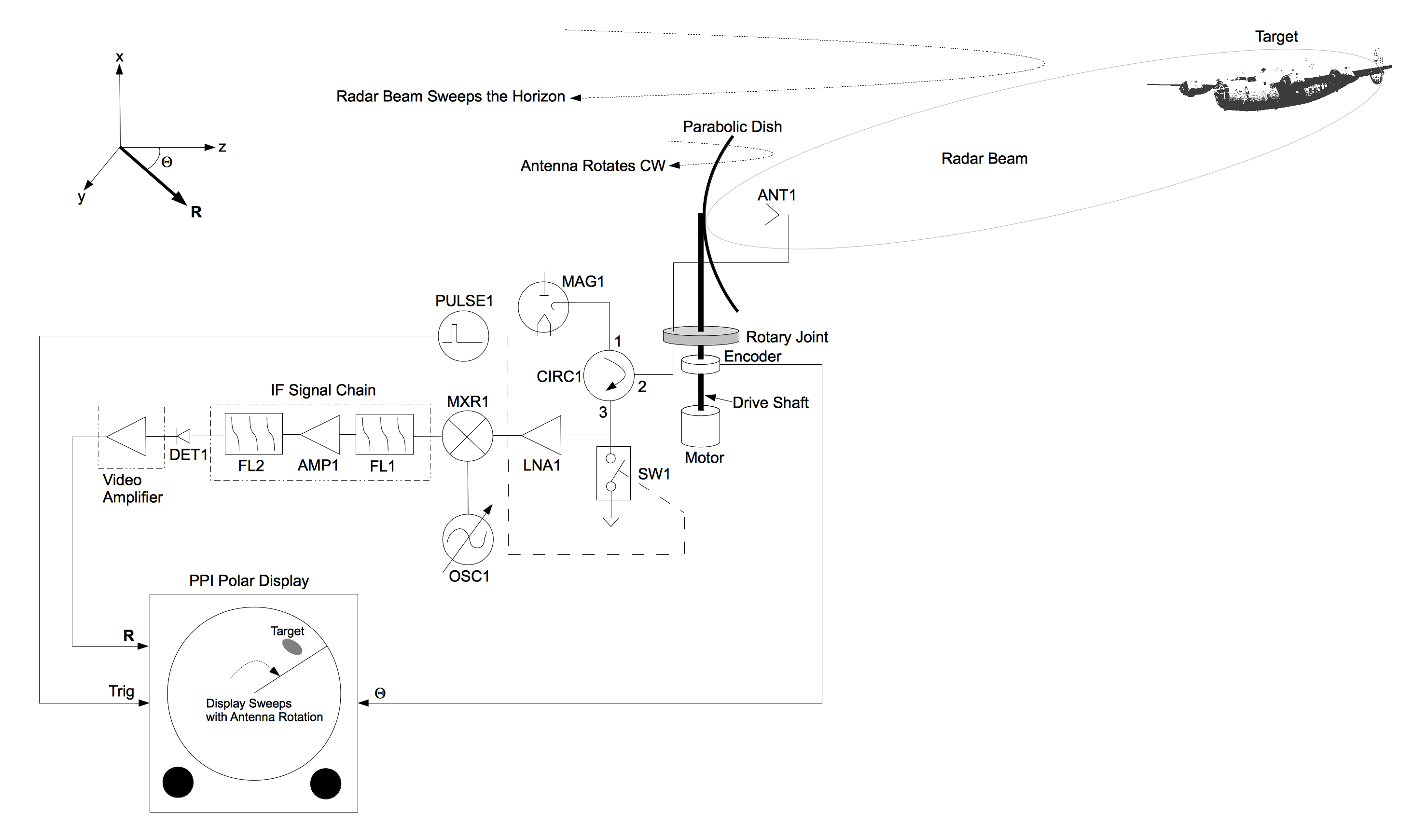
Universal Block Diagram of Pulse Radar - Radartutorial

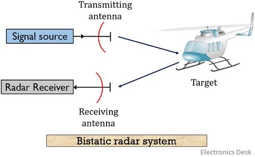
Passive radar - Wikipedia
FMCW Radar - Electronics Club Radar Engineering FMCW Radar ...

Introduction of Radar | Radar-Basics, types, working ...
RADAR - Basics, Types, Working, Range Equation & Its Applications
/Year_4/ECE%20451%20L_Radar_Eng_and_Facsimile/Introduction_to_Radar/Images/Radar%20Block%20Diagram.PNG)
Introduction to Radar Systems
ARDUINO BASED RADAR SYSTEM

Moving Target Indicator (MTI) Radar

Radar Principle - Radartutorial
Basic Radar System Block Diagram: Fundamentals of Basic Radar ...
Design, System Integration and Testing of Radar Systems - NI
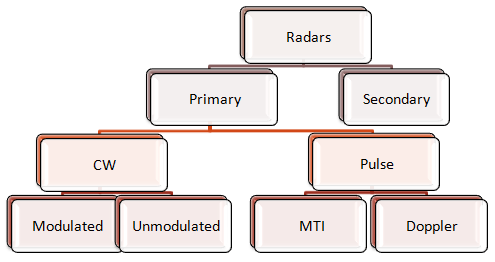
Classifications of RADAR

A technical view into modern mil/aero radar systems - EDN
2.3 Radar Block Diagram and Operation

General block diagram of the radar system. | Download ...

Shri Embedded Projects: Ultrasonic Based Radar System Project

Pulsed Radar and its Comparison with CW Radar - Electronics ...
Radar Components

Radar Principle - Radartutorial

Sensors | Free Full-Text | Portable Microwave Radar Systems ...
0 Response to "38 radar system block diagram"
Post a Comment