38 shear force and bending moment diagram solved examples
Learn to draw shear force and moment diagrams using 2 methods, step by step. We go through breaking a beam into segments, and then we learn about the relatio... Total design bending moment: (7.245) M Ed = M 0 Ed + M 2. M Ed = 512 + 60.8 = 572.8. The axial and bending capacities at Point A, Point B, Point C and Point D of the FRP-strengthened circular column with two layers are plotted in the interaction diagram (Fig. 7.61). The strengthened column has the capacity to support new loads since the new load is under the …
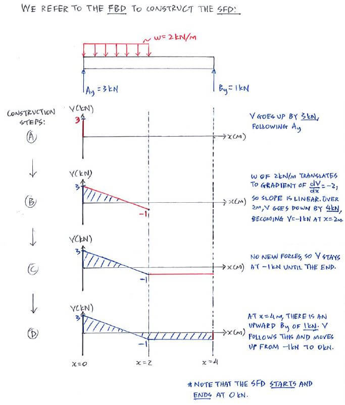
Calculate the shear force and bending moment for the beam subjected to the loads as shown in the figure, then draw the shear force diagram (SFD) and bending moment diagram (BMD). 2 kN/m 3 m A B EXAMPLE 7

Shear force and bending moment diagram solved examples
02.07.2021 · Also draw the bending moment diagram for the arch. Fig. P6.2. Parabolic arch. 6.3 Determine the shear force, axial force, and bending moment at a point under the 80 kN load on the parabolic arch shown in Figure P6.3. Fig. P6.3. Parabolic arch. Civil Engineering - Solved Examples for shear force and bending moment diagram Given below are solved examples for calculation of shear force and bending moment and plotting of the diagrams SFD and BMD for different load conditions of simply supported beam, cantilever and overhanging beam. 4.0 Building Shear and Moment Diagrams. In the last section we worked out how to evaluate the internal shear force and bending moment at a discrete location using imaginary cuts. But to draw a shear force and bending moment diagram, we need to know how these values change across the structure.
Shear force and bending moment diagram solved examples. 3.2 - Shear Force & Bending Moment Diagrams What if we sectioned the beam and exposed internal forces and moments. This exposes the internal Normal Force Shear Force Bending Moment ! What if we performed many section at ifferent values Of x, we will be able to plot the internal forces and bending moments, N(x), V(x), M(x) as a function Of position! PDF_C8_b (Shear Forces and Bending Moments in Beams) Q6: A simply supported beam with a triangularly distributed downward load is shown in Fig. Calculate reaction; draw shear force diagram; find location of V=0; calculate maximum moment, and draw the moment diagram. 6k/ft 9 ft RA = (27k)(9-6)/9= 9k A B F = (0.5x6x9) = 27k x = (2/3)(9) = 6 ft Axial Force, Shear Force and Bending Moment Diagrams for Plane Frames Previous definitions developed for shear forces and bending moments are valid for both beam and frame structures. However, application of these definitions, developed for a horizontal beam, to a frame structure will require some adjustments. Being able to draw shear force diagrams (SFD) and bending moment diagrams (BMD) is a critical skill for any student studying statics, mechanics of materials, or structural engineering. There is a long way and a quick way to do them.
14 Full PDFs related to this paper. READ PAPER. Engineering mechanics solved problems pdf Given below are solved examples for calculation of shear force and bending moment and plotting of the diagrams for different load conditions of simply supported beam, cantilever and overhanging beam. All the steps of these examples are very nicely explained and will help the students to develop their problem solving skills. Below is a simple example of what shear and moment diagrams look like, ... Let the shear force and bending moment at a section located at a distance of x ... 27.06.2017 · The bending moment at the pulley varies from – 160 Nm to 500 Nm as the torsional moment in the shaft varies from 60 Nm to 160 Nm. The frequency of the variation of the load is the same as the shaft speed. The shaft is made of cold drawn steel having an ultimate strength of 540 MPa and yield strength of 400 MPa. Determine the required diameter for an indefinite life. …
Check out http://www.engineer4free.com/structural-analysis for more free structural analysis tutorials. The course covers shear force and ... Solved Examples 8 -15 #2. Shear Force and Bending Moment 16 - 29 Introduction 16 Shear Force and Bending Moment 16 -17 Shear Force and Bending Moment Relationships 17 -19 Propped Beams and Fixed Beams 19 -22 Singularity Functions 22 Solved Examples 23 -29 #3. Stresses in Beams 30 - 40 4. A simply supported beam is subjected to a combination of loads as shown in figure. Sketch the shear force and bending moment diagrams and find the position and magnitude of maximum bending moment. Solution: To draw the shear force diagram and bending moment diagram we need R A and R B. Fig. 19.4 Shear force and bending moment Due to the relatively large negative bending moment and shear forces at intermediate supporting sections, larger girder depth than that in span center section is generally used. In addition, the continuous bridge requires only one bearing at each pier as the bearings which can be placed at the center of piers in comparison with two bearings for a simply supported bridge, …

Shear in Bending
Academia.edu is a platform for academics to share research papers.

Draw shear force and bending moment diagrams by ...
Problem 403 Beam loaded as shown in Fig. P-403. [collapse collapsed title="Click here to read or hide the general instruction"]Write shear and moment equations for the beams in the following problems. In each problem, let x be the distance measured from left end of the beam. Also, draw shear and moment diagrams, specifying values at all change of loading positions and at
Shear force and bending moment diagram practice problem #8
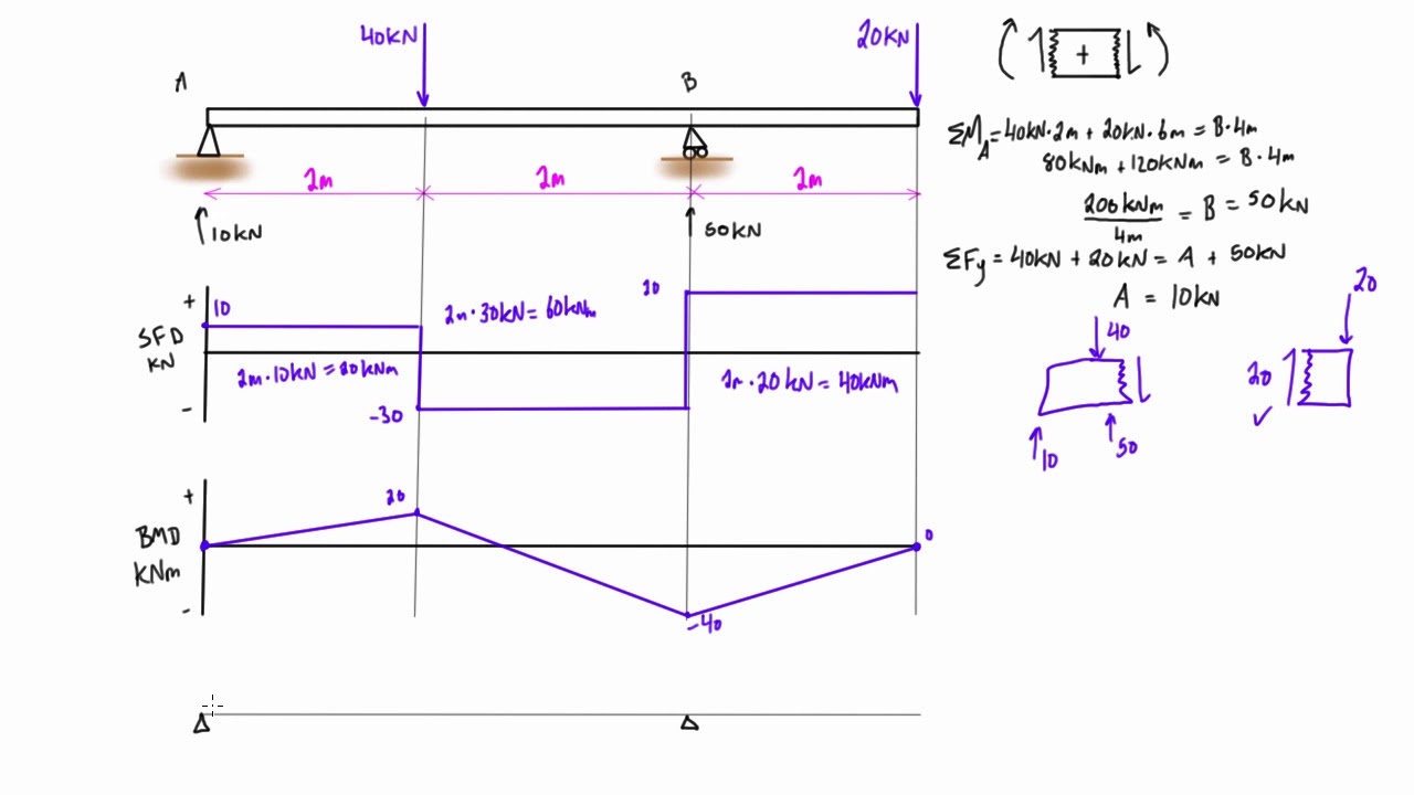
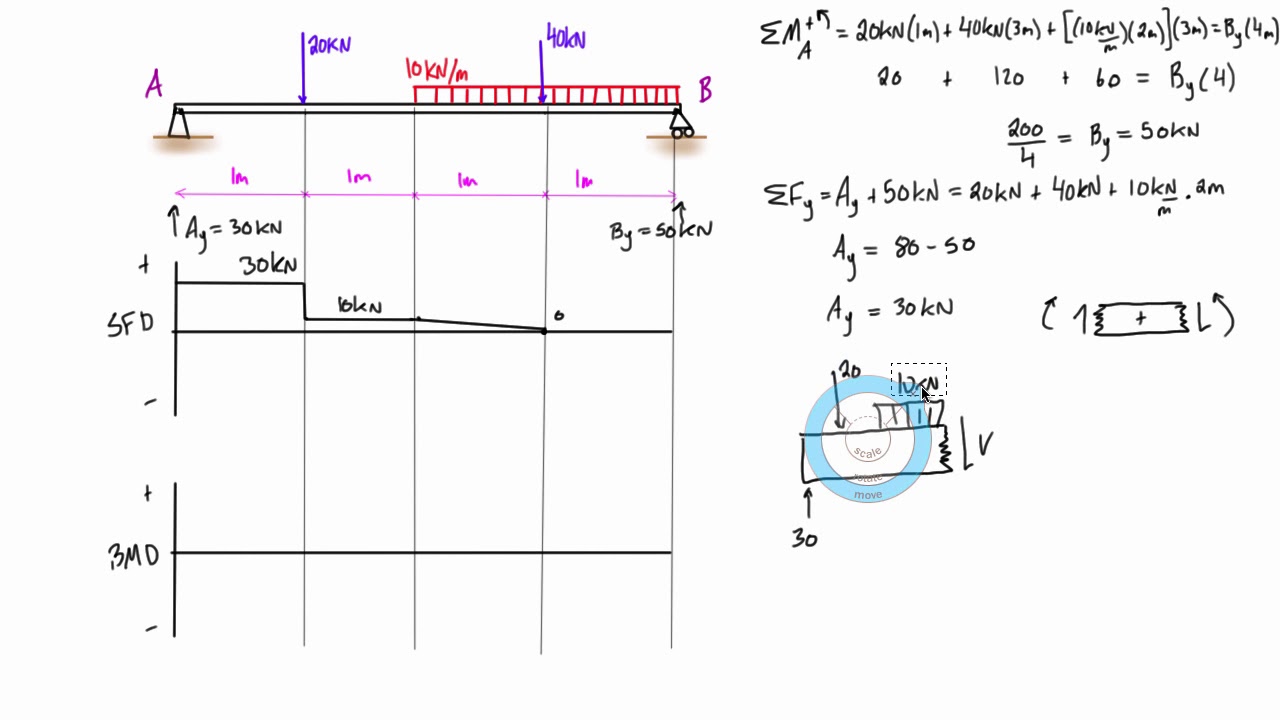
Solved Examples for Shear Force & Bending Moment Diagram 10 ... Free www.chegg.com. Examples for Shear Force & Bending Moment Diagram 10 KN 20 KN 30 KN 1 m 40 KN 10 kN/m B 2 m 5. 600 N 5 Nim B. Show transcribed image text ...
Shear Force and Bending Moment diagram for Simple supported beam
The shear force diagram is a straight line between the points (0, 13.16) and (5.6, -13.16). The bending moment diagram can be calculated directly but is more easily given by the area under the shear force diagram. Bending moments for distributed loads are quadratic functions (they are the integrals of the shear force function).
Solved] Problems 4.18 For the beam shown, derive the ...
WORKED EXAMPLE No.4 Draw the shear force diagram for the simply supported beam shown. Figure 15 SOLUTION It is necessary to first calculate the beam reactions. Total downwards load due the u.d.l.= w x length = (50 x 5) = 250 N This will act at the middle ... Construct the bending moment diagram for the beam shown in figure 22.

Shear force and bending moment diagram practice problem #2 ...
When solving the problems for Section 4.5, draw the shear-force and bending-moment diagrams approximately to scale and label all critical.
Shear force and bending moment diagram example #5: mixed distributed and point loads
S.F and B.M diagram (iv) Let us take an example: Consider a cantilever bean of 5 m length. It carries a uniformly distributed load 3 KN/m and a concentrated load of 7 kN at the free end and 10 kN at 3 meters from the fixed end. Draw SF and BM diagram. Page 131 of 429. Chapter-4 Bending Moment and Shear Force Diagram S K Mondal's
The Ultimate Guide to Shear and Moment Diagrams ...
Oct 17, 2021 · Shear Diagram. Moment Diagram. 1. Point loads cause a vertical jump in the shear diagram. The direction of the jump is the same as the sign of the point load. 2. Udl result in a straight, sloped line on the shear diagram. 3. The shear diagram is horizontal for distances along the beam with no applied load.
Civil Engineering - Solved Examples for shear force and ...
subjected to the loads as shown in the figure, then draw the shear force diagram (SFD) and bending moment diagram. (BMD). 2 kN/m. 3 m. A. B. EXAMPLE 7 ...
Moment Diagrams: Examples
Structural engineering depends upon a detailed knowledge of loads, physics and materials to understand and predict how structures support and resist self-weight and imposed loads. To apply the knowledge successfully structural engineers will need a detailed knowledge of mathematics and of relevant empirical and theoretical design codes. They will also need to know about the …
Solved] Draw the shear force and bending moment diagrams for ...
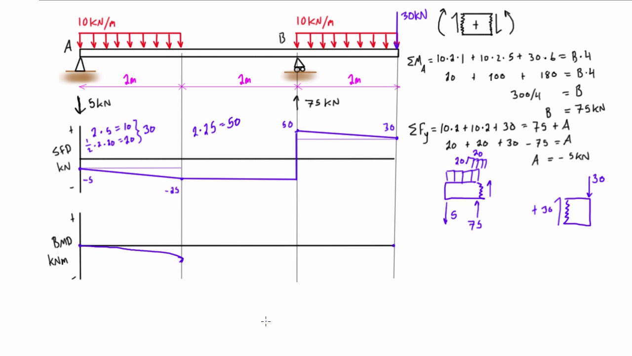
Bending Moment Diagram Simply Support Beam with UDL & Point Load Example. Draw shear force and bending moment diagram of simply supported beam carrying uniform distributed load and point loads. As shown in figure. Solution. First find reactions R1 and R2 of simply supported beam. Reactions will be equal. Since, beam is symmetrical.

SOLVED:Problem 1. For the beam shown in the figure; A is a ...
Examples Calculating Deflections (Ref: Chapter 8) Sign Convention Shear: Left Down & Right Up (Smiley: positive) Moment: Left Counter & Right Clockwise IntroReview Page 16 . Examples IntroReview Page 17 . Double Integration Deflected shapes of beams can also be calculated precisely by integrating the governing equation of beam equilibrium:. • Constants are evaluated …
Problem 9.1 Two beam segments, AC and CD, are connected ...
05.03.2021 · 9.1 Draw the influence line for the shear force and moment at a section n at the midspan of the simply supported beam shown in Figure P9.1. Fig. P9.1. Simply supported beam. 9.2 Draw the influence lines for the reaction at A and B and the shear and the bending moment at point C of the beam with overhanging ends, as shown in Figure P9.2. Fig. P9 ...
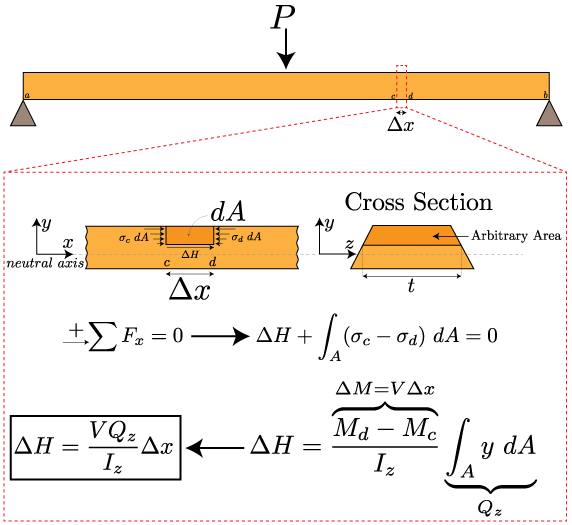
Mechanics of Materials: Bending – Shear Stress » Mechanics of ...
The shearing force suffers sudden changes when passing through a load point. The change is equal to the load. The bending Moment diagram is a series of straight lines between loads. The slope of the lines is equal to the shearing force between the loading points. Uniformly Distributed Loads Example: 1 [imperial] Example - Example 3 Problem
Shear force and Bending Moment diagram for overhanging beam
Bending Moment With Worked Examples' 'Shear Force and Moment Diagrams worldclasscad com May 4th, 2018 - 9 1 C h a p t e r 9 Shear Force and Moment Diagrams In this chapter you will learn the following to World Class standards Making a Shear Force Diagram Simple Shear Force ... the Bending Moment Diagram BMD Shear Force Diagram SFD Axial Force ...

Drawing Shear Force, Bending Moment Diagram » File Exchange ...
Unknowns to be solved for are usually redundant forces ... Find the reactions and draw the Shear Force and Bending Moment Diagrams of the beam. ForceMethod Page 5 . Example: Frames ... • Draw the influence lines for the shear -force and bending -moment at point C for the following beam.
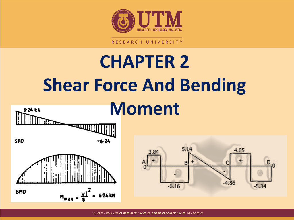
CHAPTER 2 Shear Force And Bending Moment
Example On Cantilever Beam Problem :- Calculate the value and draw a bending moment and shear force diagram for following cantilever beam shown in fig. 31/12/16 RAVI VISHWAKARMA 15 16. Solution Problem The support reaction for given beam can be easily determined by following method. Dy = (4×2 ×1/2) + (2 ×4) Dy =10 kN 31/12/16 RAVI VISHWAKARMA 16
The Ultimate Guide to Shear and Moment Diagrams ...
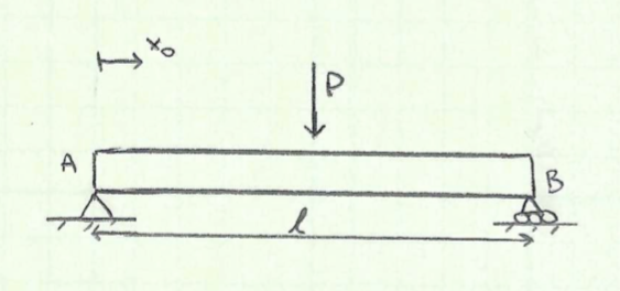
To understand the shear forces and bending moments in a beam, we will look at a simple example. In Diagram 1, we have shown a simply supported 20 ft. beam with a load of 10,000 lb. acting downward right at the center of the beam. Due to symmetry the two support forces will be equal, with a value of 5000 lb. each.

Structural Engineering - Structural Mechanics, Analysis ...
Draw the internal shear force and bending moment diagram using the Graphical Method. Show step-by-step process and free body diagrams associated with said process. Question: Draw the internal shear force and bending moment diagram using the Graphical Method. Show step-by-step process and free body diagrams associated with said process.

Shear force and bending moment diagram practice problem #1
4.3 Shear Forces and Bending Moments Consider a cantilever beam with a concentrated load P applied at the end A, at the cross section mn, the shear force and bending moment are found Fy = 0 V = P M = 0 M = P x sign conventions (deformation sign conventions) the shear force tends to rotate the material clockwise is defined as positive
Shear force and bending moment diagram practice problem #7
4.4 Area Method for Drawing Shear- Moment Diagrams Useful relationships between the loading, shear force, and bending moment can be derived from the equilibrium equations. These relationships enable us to plot the shear force diagram directly from the load diagram, and then construct the bending moment diagram from the shear force diagram.
Mechanics of Materials Chapter 4 Shear and Moment In Beams
Draw one bending moment and one shearing force diagram for the given beam by combining the diagrams in step 9. Example 12.1 Using the moment distribution method, determine the end moments and the reactions at the supports of the beam shown in Figure 12.6a .

Shear in Bending
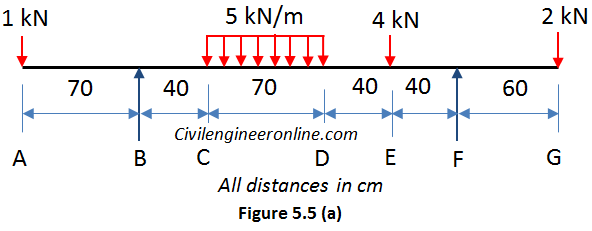
SHEAR FORCES AND BENDING MOMENT DIAMGRAMS Definition of Shear force and bending moment A shear force (SF) is defined as the algebraic sum of all the vertical forces, either to the left or to the right hand side of the section. Fig. 5.4. Shear force at section

Shear-force and bending-moment diagrams along the base of the ...
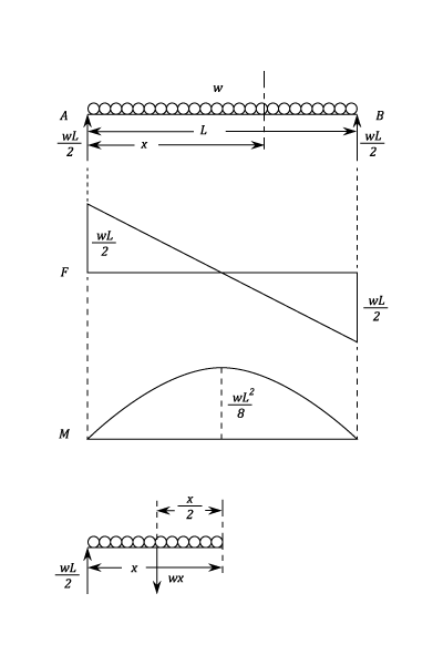
Shear and Moment Diagrams Consider a simple beam shown of length L that carries a uniform load of w (N/m) throughout its length and is held in equilibrium by reactions R 1 and R 2. Assume that the beam is cut at point C a distance of x from he left support and the portion of the beam to the right of C be removed.

Problem while solving for the moment of a cantilever beam ...
Problem 10: Bending Moment and Shear force A beam with a hinge is loaded as above. Draw the shear force and bending moment diagram. Solution: Concept: A hinge can transfer axial force and shear force but not bending moment. So, bending moment at the hinge location is zero. Also, without the hinge, the system is statically indeterminate (to a ...
Bending Moment & shear force
4.0 Building Shear and Moment Diagrams. In the last section we worked out how to evaluate the internal shear force and bending moment at a discrete location using imaginary cuts. But to draw a shear force and bending moment diagram, we need to know how these values change across the structure.
Bending Moment & shear force
Civil Engineering - Solved Examples for shear force and bending moment diagram Given below are solved examples for calculation of shear force and bending moment and plotting of the diagrams SFD and BMD for different load conditions of simply supported beam, cantilever and overhanging beam.
TU05_Week 6_Functions for shear force and bending moment ...
02.07.2021 · Also draw the bending moment diagram for the arch. Fig. P6.2. Parabolic arch. 6.3 Determine the shear force, axial force, and bending moment at a point under the 80 kN load on the parabolic arch shown in Figure P6.3. Fig. P6.3. Parabolic arch.

Cantilever Beam: Shear force and bending moment diagram practice problem | Facebook
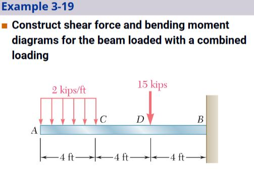
Solved Example 3-19 Construct shear force and bending moment ...
Beams – SFD and BMD
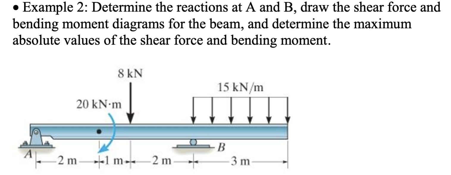
Solved • Example 2: Determine the reactions at A and B, draw ...
Example - Direct method | C5.3 Shear Force and Bending Moment ...
![Shear Force and Bending Moment Diagrams [SFD & BMD] - ppt ...](https://slideplayer.com/slide/14400151/90/images/34/Shear+Force+Calculations%3A.jpg)
Shear Force and Bending Moment Diagrams [SFD & BMD] - ppt ...
DE-12: Lesson 19. SOLVED EXAMPLES BASED ON SHEAR FORCE AND ...
Shear Force and Bending Moment - Materials - Engineering ...
DE-12: Lesson 19. SOLVED EXAMPLES BASED ON SHEAR FORCE AND ...
4.5 Practice Problems | Learn About Structures
0 Response to "38 shear force and bending moment diagram solved examples"
Post a Comment