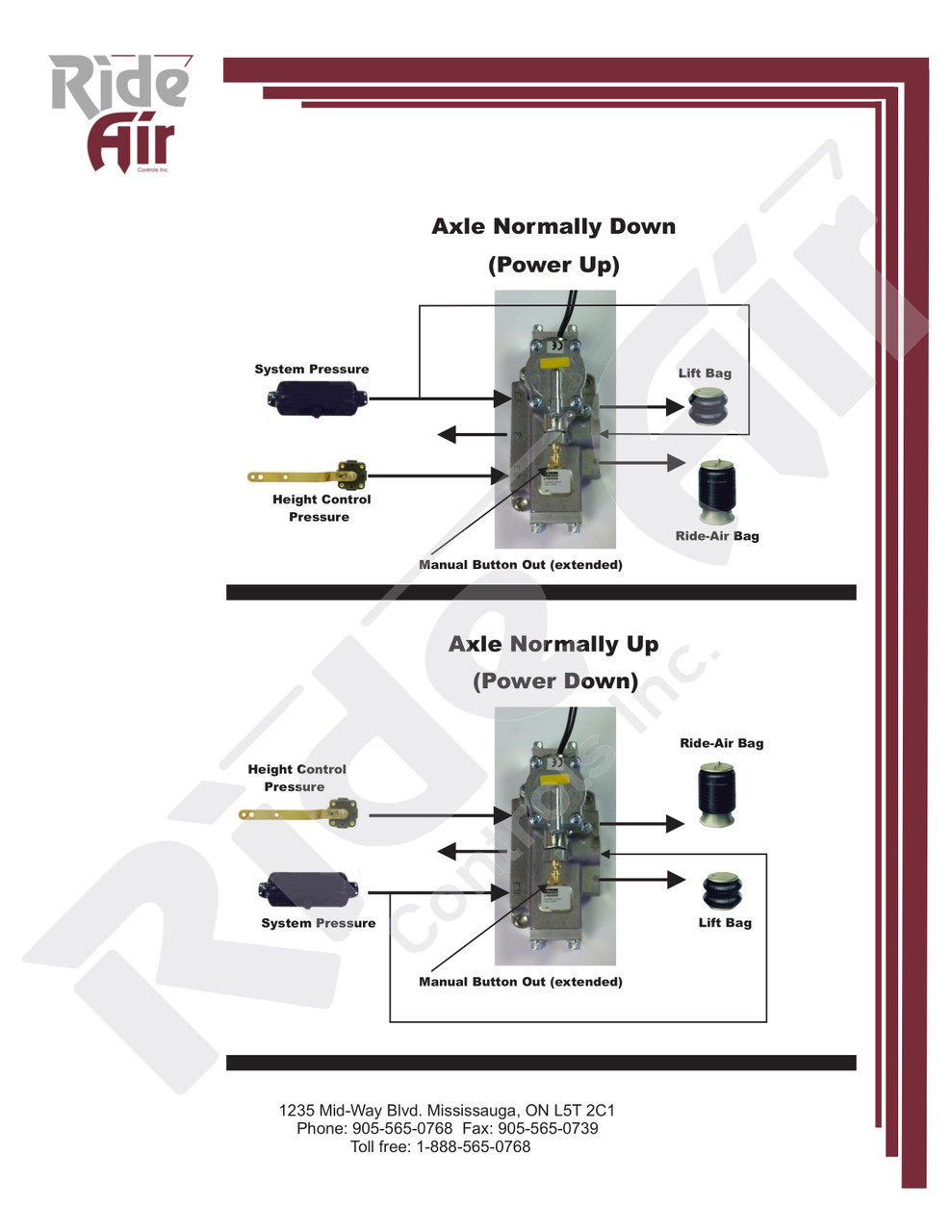
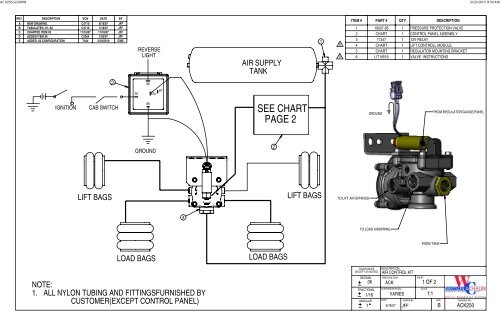
39 lift axle plumbing diagram
the area of the lift axle so that this is visible. - press the yellow cap loosely on the tube and make sure this engages. - remove the pressure gauge from the test con-nection and replace the protective cap. PRECAUTION-DANGER Automatic lowering of lift axle(s) after reaching the switching pressure. Do not stay in the area of the lift axle. 7 8 ... 3A750/900 INSTALLATION INSTRUCTIONS REV - 102k AL Series Manual REV C 09/11 2.6MB AL2200 Installation Manual REV A 08/16 3.6 MB Axle Manual REV A 05/11 12.6Mb Axle Seat Welding Procedure REV - 04/09 143k Bushing Tool Assembly - TA Series REV B 03/15 309k CL-Coil Lift Manual REV - 10/85 468k Drawbar Series Manual REV - 993k Eccentric Collar ...
Buy the best range of Caravan Water Filters in Australia. Shop for all Caravan Pump, Filter & Accumulator online at Caravans Plus. You'll get a good deal on leading brands including Flojet, SHURflo, B.E.S.T Water Filters.
Lift axle plumbing diagram
The relief valve on the hydraulic unit comes factory set In order to lift vehicle during adjustment, connect at 13.8 MPa (2000 psi) for 2135 mm (84 in) lift height batteries or plug an alternate 24 V source into grey and 20.7 MPa (3000 psi) for 2995 mm (118 in) lift connector attached to vehicle. Dual Pressure Applications - Lift Axle Control: All 5 ported valves offered by Velvac Inc, and shown in this document are capable of being used as dual pressure valves for lift axle control applications. • Dual Pressure Function: air is supplied to ports #3 and port #5 and port #1 becomes a common exhaust port. L1182 Controls Parts Catalog (Lift axle control kits2) ... refer to page 2 for applicable drawings. 2 Control kits include installation information and plumbing diagrams, also available upon request. ... UNDER BEAM LIFT™ (UBL™) Hardware Kit Information and Requirements
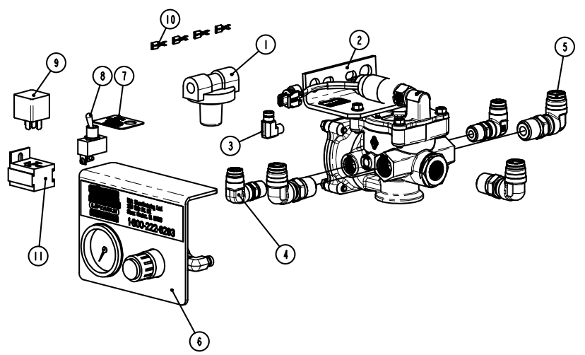
Lift axle plumbing diagram. Nov 26, 2018 · Axle Suspension Brakes(28) Break Away Switch(1) ... Plumbing(75) Anderson 4 Way Valve(13) ... 12V Block Diagram & Diagnostics V2.pdf: 14 Sep 2020 14:08: Non-Steer suspension with lift axle up when ignition is off. NOTES: 1) Use 1/4", 3/8", and 1/2" DOT airline for all plumbing between fittings as shown per figure 2. Use brass DOT fittings for all plumbing connections. Use 14-gage primary wire for all electrical connections. 2 lacv installation & calibration 97117-187 rev b table of contents introduction 3 important safety notices 3 lift axle control valves 4 auto/auto operation 5 enclosure 5 manual override 5 restore axle operation 5 lacv inspection 6 trailer air supply 8 lacv operation 9 single lift triaxle layout 13 dual lift triaxle layout 14 lacv adjustment 16 proper operating pressures 16 ... TRAILER LIFT AXLE PLUMBING 099-30819-03 STANDARD PLUMBING KIT 510-05588-20 2 Pilot Valves 510-15320-19 1 2 way Check Valve 510-05020-00 1 Ball Valve 512-05006-66 3 T-Block 3/8" npt 511-99607-00 40ft 3/8" Green Tubing 567-01213-00 1 Legend Plate
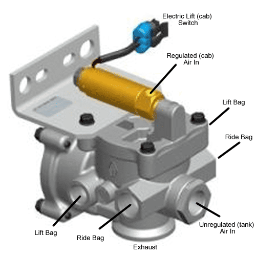
The ILAS-E lift axle valve controls airflow to inflate or deflate the lift axle bellows in order to either raise or lower the lift axle. When raising, the ILAS-E valve isolates and exhausts the air suspension of the lift axle; enabling the raising of the lift axle. When lowering, the ILAS-E exhausts the lift bellows, inflates the lift axle Support this channel -- https://www.paypal.me/SergeiDratchev 1. Includes complete suspension, torque rods, axle brackets and frame brackets and all hardware. 2. No add-on lift axles. 3. Approved one lift axle only. Maximum 50,000 pounds load on suspension for site travel. 4. Not approved with trailer belly lift axles. 5. Available for low profi le for disc brakes. TECHNICAL NOTES FIFTH WHEEL MOUNTING ... if lift axle is operated by an automatic or semi-automatic lift axle control system, such system may cause lift axle to automatically raise or lower under different conditions . lift axle activation and movement may vary depending on the brand, configuration, and operating condition of the lift axle control system and / or other factors .
Trailer Lift Axle Plumbing 20. PNEUMATICS Gauge, Regulator, Check Valve PART NO. ITEM Air Gauge 510-05003-00 Silicon Filled with 1/4" npt Tem Mounted 510-05004-00 Silicon Filled Flange Mounted 510-05022-00 Rear Mounted (lighted) (Dial-A-Ride) PART NO. ITEM Regulators ... The lift axle(s) automatically lower when the vehicle is loaded. The control button is then used to raise the lift axle when the vehicle is unloaded. When the vehicle is unloaded, the control button can be pull out to bring the axle(s) down manually. NOTE: To determine the desired Ps1 pressure, connect gauge to air spring line and load the ... E S Inter-Axle Lock F R Inside/Outside Air G M Fifth Wheel Release H A Fifth Wheel Slide K N Air Horn or Neutral Control J R Auxiliary Axle 1 J R First Lift Axle G M Second Lift Axle J R First Lift Axle G M Second Lift Axle P M Third Lift Axle Mack Body Builder Instructions CHU, CXU, GU, TD, MRU, LR The Lift delivery ports are the connection from the LACM to the Lift bags. One port is connected to each Lift bag. GT recommends use of 3/8" Lift delivery lines to ensure adequate airflow. 5. (OPTIONAL) GAUGE PORT The optional Gauge port is common with the Load delivery ports. This port should be connected to the auxiliary axle's Load bag air
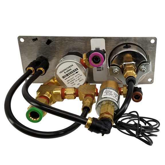
Lift Axle Control Box w/ reg - gauge - pilot valve. Part # R986060 Lift Axle Control Box w/ reg - gauge - pilot valve. These controls are used with lift axle set-ups that require an operator adjusted regulator. Box Dimensions - 12" x 12" x 6" Rubber Latch standard on powder coated boxes- Stainless steel latch standard on SS boxes. Part ...
Lift axle function Lift axle integration diagram The lift axle is automatically raised when the primary axle load is below the safe working weight using either using a system of fully integrated electronic controls and interlocks or remote control from the existing vehicle electronics, saving on tyre wear and improving fuel economy.
OPTION 3: Kit will be installed on a non-steer suspension in which the driver wants the lift axle to be up when ignition is off. OPTION 4: Kit will be installed on a non-steer suspension in which the driver wants the lift axle to be down when ignition is off. FIG. 2 ITEM PART DESCRIPTION 1 VALVE-SOLENOID, ASSEMBLY 2 VALVE-PRESSURE PROTECTION
if lift axle is operated by an automatic or semi-automatic lift axle control system, such system may cause lift axle to automatically raise or lower under different conditions . lift axle activation and movement may vary depending on the brand, configuration, and operating condition of the lift axle control system and / or other factors .
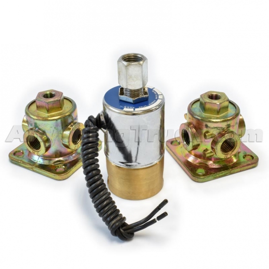
Trailer Lift Axle Air Plumbing Diagram gutscheinshow de. 1871 State Route 44 P O Box 277 Randolph Ohio 44265. ABS PLUMBING VALVES AND 2 / 18. ACCESSORIES Mac Trailer. PTP 90554615 3 Way Pilot Valve Use in Air Suspension Dump. Lift Axle Parts newlifeparts com. 62101005 Lift Axle Valve
ing of a lift axle or deck of a trailer. They also offer an automatic feature unique to each valve. The ILAS® III can automatically lower and raise lift axles without operator intervention. The COLAS® can automatically reset deck height to the normal ride height of the trailer without operator intervention. Looking For A Quality Supplier
Buy the best range of Caravan RV Camping Accessories in Australia. Shop for all Caravan Accessories online at Caravans Plus. Whether you're looking for Kitchen Accessories, 12V & Assisted Movers, Tableware, Cookware, Laundry & Cleaning, Camping Accessories, Safety Gear, Steps & Ladders, Outdoor Furniture, Bike Racks, Levelling & Jacks, Hoses & Power Leads, Storage Accessories, Security & Locks ...
L1182 Controls Parts Catalog (Lift axle control kits2) ... refer to page 2 for applicable drawings. 2 Control kits include installation information and plumbing diagrams, also available upon request. ... UNDER BEAM LIFT™ (UBL™) Hardware Kit Information and Requirements
Dual Pressure Applications - Lift Axle Control: All 5 ported valves offered by Velvac Inc, and shown in this document are capable of being used as dual pressure valves for lift axle control applications. • Dual Pressure Function: air is supplied to ports #3 and port #5 and port #1 becomes a common exhaust port.
The relief valve on the hydraulic unit comes factory set In order to lift vehicle during adjustment, connect at 13.8 MPa (2000 psi) for 2135 mm (84 in) lift height batteries or plug an alternate 24 V source into grey and 20.7 MPa (3000 psi) for 2995 mm (118 in) lift connector attached to vehicle.





0 Response to "39 lift axle plumbing diagram"
Post a Comment