40 what process is described in the following diagram
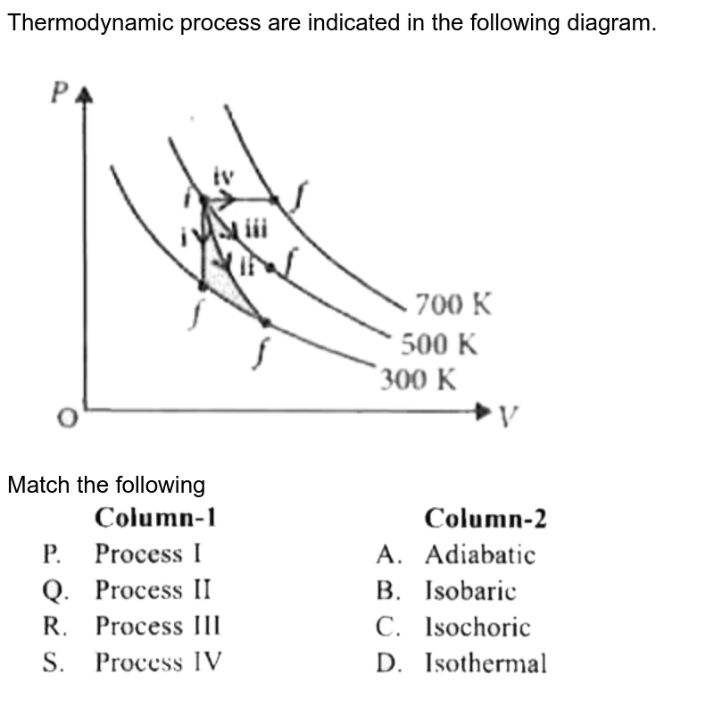
Dec 10, 2018 · What process is described in the following diagram? (2 points) Two pyruvate molecules are converted to two ethyl alcohol molecules and two carbon dioxide molecules. In the process, two NADPH molecules are converted to two NAD+ molecules. Krebs cycle Fermentation Glycolysis Electron transport chain The diagram below shows a process in Earth's crust. Which of the following statements best describes the process in the diagram. A Converging plates from Mountains B Converging plates from Volcanoes C Diverging plates form Mountains D Diverging plates form a rift valley I think it is D. Can someone please check. To find picture google question open study link is there. That is where you will ...
DFD describes the processes that are involved in a system to transfer data from the input to the file storage and reports generation. Data flow diagrams can be divided into logical and physical. The logical data flow diagram describes flow of data through a system to perform certain functionality of a business.

What process is described in the following diagram
Process diagrams, called "flow diagrams" by TOGAF, are used to model the sequence of activities within a process. Process modeling formalizes practices and describes the manner in which they should take place. Flow diagrams represent process participants, activity sequences, information exchanged during a process, and trigger events. Process state: The state of a process is defined by the current activity of that process. During execution, process changes its state . The process can be in any one of the following three possible states. 1) Running (actually using the CPU at that time and running). 2) Ready (runnable; temporarily stopped to allow another process run). Figure 3.2 - Diagram of process state. 3.1.3 Process Control Block. For each process there is a Process Control Block, PCB, which stores the following ( types of ) process-specific information, as illustrated in Figure 3.1. ( Specific details may vary from system to system. ) Process State - Running, waiting, etc., as discussed above.
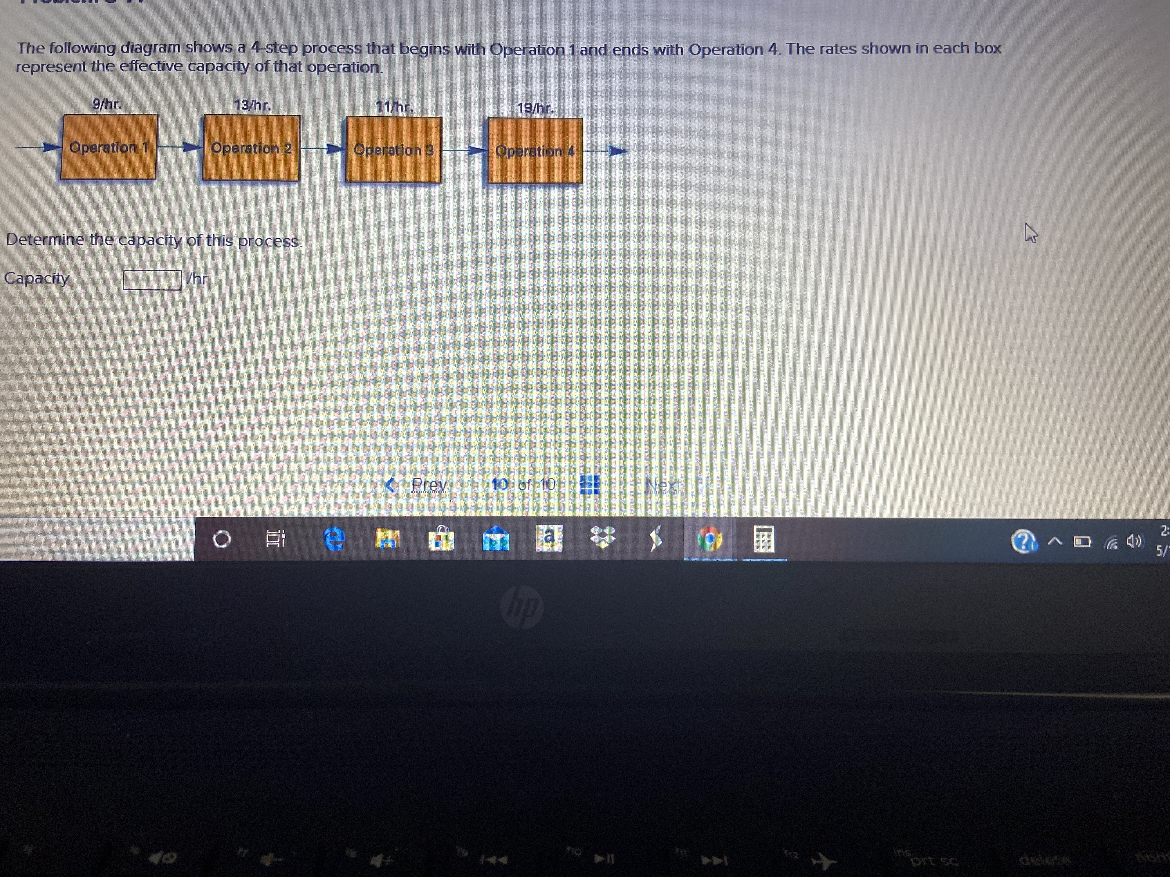
What process is described in the following diagram. Solution for Describe Process Specification and techniques for the following diagram. Please follow the same format as attached in this pdf:… The following diagram describes a process that consists of eight separate operations, with sequential relationships and capacities (units per hour) as shown. a. What is the current capacity of the entire process? Answer: The maximum capacity of the line is 5 units per hour. In the communication process diagram, the stage after the message is sent, where the analysis and interpretation of the language and symbols sent by the source takes place, is best known as: a. noise. Oct 14, 2021 · Both process flow diagrams and P&IDs contain a series of standard symbols for users to describe a process. P&IDs normally include more details than process flow diagrams, since the latter type mainly show the relationship between main equipments. Usually, a process flow diagram includes process pipelines, major equipment items and control ...
The different states that a process is in during its execution are explained using the following diagram − The following are the states − New - The process is in the new state when it has just been created. Ready - The process is waiting to be assigned the processor by the short-term scheduler. the diagram shows the process of photosynthesis. the stacked structure is a granum, which contains the thylakoids. The light-dependent reactions occur in and across the thylakoid membrane. What are the two reactants and two products for the process illustrated above? Structure of the Process Control Block. The process control stores many data items that are needed for efficient process management. Some of these data items are explained with the help of the given diagram −. The following are the data items −. Process State. This specifies the process state i.e. new, ready, running, waiting or terminated. ConceptDraw is Professional business process mapping software for making process flow diagram, workflow diagram, general flowcharts and technical illustrations for business documents. It is includes rich examples, templates, process flowchart symbols. ConceptDraw flowchart maker allows you to easier create a process flowchart. Use a variety of drawing tools, smart connectors, flowchart symbols ...
Photosynthesis. Photosynthesis is a process by which phototrophs convert light energy into chemical energy, which is later used to fuel cellular activities. The chemical energy is stored in the form of sugars, which are created from water and carbon dioxide. 3,12,343. 2. Use the Passive Tense. The diagram gives you several of the verbs that you need to describe each stage e.g. drying, soaking, polishing, flattening. Again, you have the problem of avoiding using these words exactly as they are in the text.. So using the Passive Tense gives you an easy solution.. Even better, when describing a process you only use the Present Simple Passive. A flowchart is a picture of the separate steps of a process in sequential order. It is a generic tool that can be adapted for a wide variety of purposes, and can be used to describe various processes, such as a manufacturing process, an administrative or service process, or a project plan. It's a common process analysis tool and one of the ... What process is described in the following diagram? two pyruvate molecules are converted to two ethyl alcohol molecules and two carbon dioxide molecules. in the process, two nadph molecules are converted to two nad+ molecules. krebs cycle fermentation glycolysis electron transport chain
• A process is not the same as "program" A program is a passive text of executable codes resides in disk. A process is an active entity ripe for execution (must have a program counter, stack and data section). Multiple people can run the same program, each running a copy of the same program text, but each is a distinct process. • Type ...
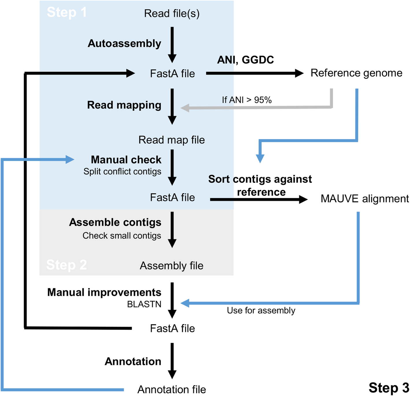
Jul 09, 2019 · In the IELTS writing exam, you may be required to describe a process diagram. This will be part of writing task 1, a section in which you might normally expect to encounter a line graph, bar chart, or table. Describing a process diagram might fill you with fear, but you shouldn’t worry too much.
Problem 2 Chapter 5: The following diagram describes a service process where customers go through either of two parallel three-step processes and then merge into a single line for the final step. The numbers in parentheses are the times in minutes for each step of the process.
The following diagram describes a process that consists of eight separate operations, with sequential relationships and capacities (units per hour) as shown below. Capacity: Operation A: 14/hr Operation B: 11/hr Operation C: Question: The following diagram describes a process that consists of eight separate operations, with sequential ...
Following are the major steps involved in the process of the carbon cycle: Carbon present in the atmosphere is absorbed by plants for photosynthesis. These plants are then consumed by animals and carbon gets bioaccumulated into their bodies. These animals and plants eventually die, and upon decomposing, carbon is released back into the atmosphere.
A piping and instrumentation diagram displays the piping components (for example equipment, valves, reducers and so on) of an actual physical process flow and is often used in the engineering projects, such as setting up steam boilers, heat exchangers, electric boilers and more.. To read a piping and instrumentation diagram, simply break down the overall diagram into smaller parts and then ...
The process diagrams illustrate the production of five different teas, from harvest to packaging. There is also a diagram showing a similar six step process for coffee beans. Here is a possible introduction for a hydroelectric process:
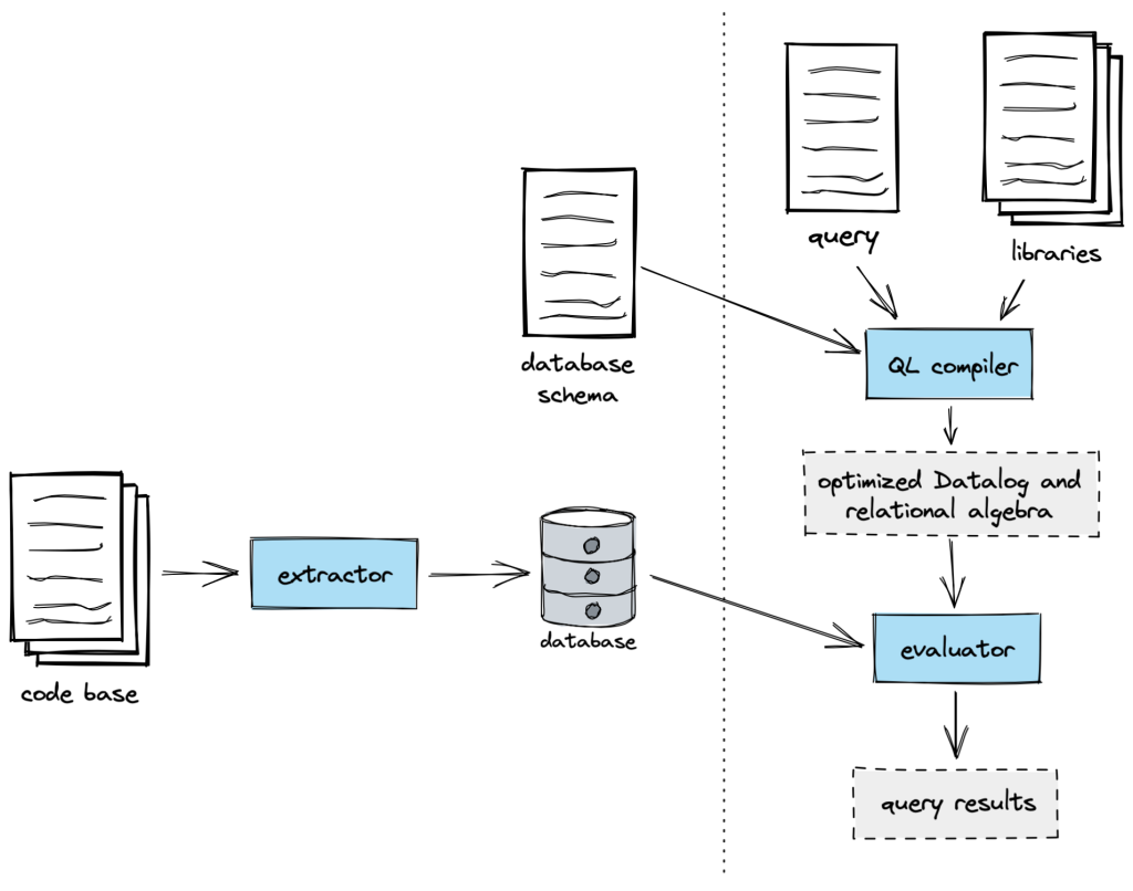
A business process model is a graphical representation of a business process or workflow and its related sub-processes. Process modeling generates comprehensive, quantitative activity diagrams and flowcharts containing critical insights into the functioning of a given process, including the following: Events and activities that occur within a ...
The following diagram describes a process that consists of eight separate. operations, with sequential relationships and capacities (units per hour) as shown. 11/hr 10/hr 6/hr 1 > 2 > 3 >>>>> 35/hr 32/hr 7 > 8 8/hr 9/hr 12/hr 4 > 5 > 6 a. What is the current capacity of the entire process? ...
Logical database structure models, including UML Class Diagrams, must be able to describe which of the following? A) The attributes of the entities. B) The activities performed in the business process. C) The operations performed on the database. D) The Bachman diagram.
Include: When a use case is depicted as using the functionality of another use case in a diagram, this relationship between the use cases is named as an include relationship. Literally speaking, in an include relationship, a use case includes the functionality described in another use case as a part of its business process flow. An include ...
Process Map Symbols. Each step in a process is represented by a shape in a process map. These shapes are also called flowchart shapes. There are nearly 30 standard shapes that you can use in process mapping.However, we think for most people, using a handful of the most common shapes will be easier to understand.
Figure 3.2 - Diagram of process state. 3.1.3 Process Control Block. For each process there is a Process Control Block, PCB, which stores the following ( types of ) process-specific information, as illustrated in Figure 3.1. ( Specific details may vary from system to system. ) Process State - Running, waiting, etc., as discussed above.
Process state: The state of a process is defined by the current activity of that process. During execution, process changes its state . The process can be in any one of the following three possible states. 1) Running (actually using the CPU at that time and running). 2) Ready (runnable; temporarily stopped to allow another process run).
Process diagrams, called "flow diagrams" by TOGAF, are used to model the sequence of activities within a process. Process modeling formalizes practices and describes the manner in which they should take place. Flow diagrams represent process participants, activity sequences, information exchanged during a process, and trigger events.
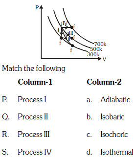

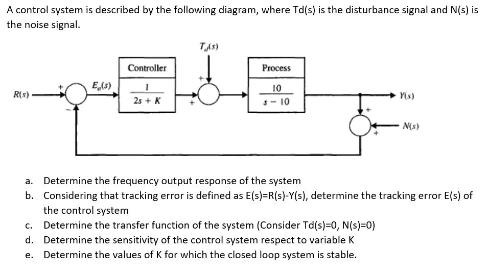
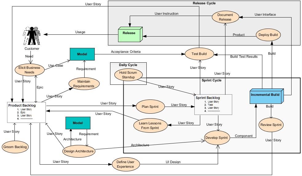
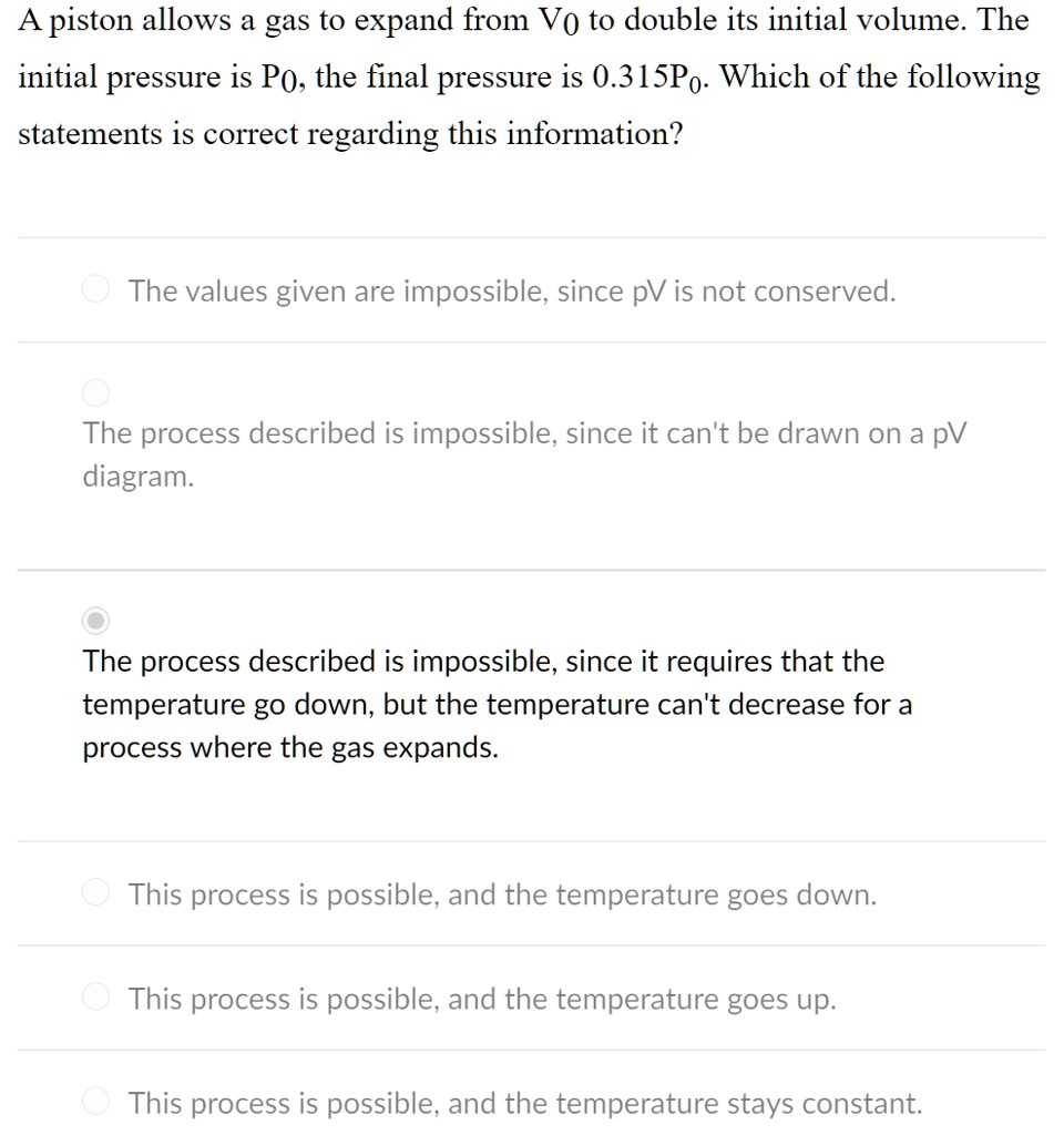
![The process shown in the diagramis called [______]​ - Brainly.com](https://us-static.z-dn.net/files/d91/5e79c6098574e1e8d645670d0fd2a12b.jpg)













0 Response to "40 what process is described in the following diagram"
Post a Comment