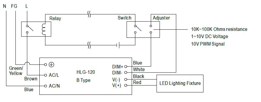
36 led driver wiring diagram
Wiring LEDs Correctly: Series & Parallel Circuits Explained The image to the right shows an example: To wire a series circuit like the one shown, the positive output from the driver connects to the positive of the first LED and from that LED a connection is made from the negative to the positive of the second LED and so on, until the last LED in the circuit. Arduino Nano: Pinout, Wiring Diagram and Programming 27.02.2021 · In this post I want to talk about the Arduino Nano: pinout, wiring diagram and programming. What is an Arduino Nano? Arduino Nano is the smallest, typical microcontroller board based on ATmega328P microcontroller made by Atmel. Arduino Nano board dimension is 18 x 45 mm. Where is the board used? Nowadays Arduino Nano board is used in thousands of …
PDF LED Driver Installation Best Practices Guide (041551) Driver terminals To EcoSystem TM Digital Link compatible devices Installing or servicing LED driver or light engine WARNING: Shock hazard. May result in serious injury or death. Disconnect power before servicing or installing. Driver Wiring For proper wiring, follow wiring schematic on driver being installed. Driver photos are for reference only.

Led driver wiring diagram
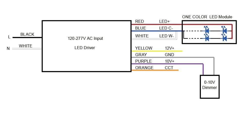
circuitdigest.com › electronic-circuits › 2-wayHow to Connect a 2-Way Switch (with Circuit Diagram) Nov 23, 2017 · Where, 0 represents the OFF condition and 1 represents the ON condition. How to Connect 2-way Switch Wiring using Three-wire control. This is the new method to make a 2-way switch connection and it is slightly different from the two-wire control method. PDF Wiring Diagram Ltf WIRING DIAGRAM CAUTION: - Always follow local electrical code regulations when installing LED drivers & fixtures. - DO NOT attach 0-10V dimming wires to hot / line voltage wire. - Leave wire caps on 0-10V dimming wires when not in use to prevent short circuit. PDF LED Dimming: What you need to know - Energy • LEDs typically need a "Driver" • Dimming an LED source can change the behavior of the Driver • LED dimming performance is determined by Driver capability and compatibility with the dimming equipment • Multiple compatibility issues are rooted in circuit level interactions between the LED Driver and dimmer
Led driver wiring diagram. motorcycle diagram wiring - Vector Nakia Linear LED driver circuit diagram 30V adjustable current. Japanese brand Honda is known as one of the largest motorcycle manufacturers. This information outlines the wires location color and polarity to help you identify the proper connection spots in the vehicle. Use this 7 pin trailer wiring diagram to properly wire your 7 pin trailer plug. Led Wiring Diagram - Wirings Diagram Led Wiring Diagram - led wiring diagram, led wiring diagram 120v, led wiring diagram 12v, Every electric structure consists of various diverse components. Each part ought to be placed and connected with other parts in specific way. Otherwise, the structure will not work as it ought to be. › faq-wiringTrailer Wiring Diagrams | etrailer.com Trailer Wiring Connectors Various connectors are available from four to seven pins that allow for the transfer of power for the lighting as well as auxiliary functions such as an electric trailer brake controller, backup lights, or a 12V power supply for a winch or interior trailer lights. 50w Led Driver Circuit Diagram - Wiring Diagram Pictures LED Driver Xitanium Specifications Wiring Diagram 50W V A V XICVCNH1. Here's a really simple and inexpensive ($1) LED driver circuit. The circuit is a "constant current source", which means that it keeps the LED brightness constant no matter what power supply you use or surrounding environmental conditions you subject the LED's to.
12 Volt Led Light Schematic Diagram - Wiring Diagram Line 12 Volt Led Light Schematic Diagram Wiring Diagram Line Wiring Diagram. Wiring Diagram Line We are make source the schematics, wiring diagrams and technical photos ... through relay ledultiplexing arduino forum cr4 discussion thread 5624 dimmer 12w bulb techliminals constant cur driver automatic emergency 4 transformerless power supply ... 20 Watt Led Driver Circuit Diagram - U Wiring Gx_2680 1w led driver circuit diagram watt led circuit diagram 1 watt led wiring diagram. Its cheapest project in english. LED current in amps 125 R3 so for a current of 550mA set R3 to 22 ohms youll need a power resistor usually R3 power in watts 156 R3 this circuit also has the drawback that the only way to use it with a micro-controller or ... PDF Wiring Diagram Ltf LED DRIVER WHITE BLACK HOT/LINE COMMON/NEUTRAL 0-10V DIMMER GRAY (-) PURPLE (+) 0-10V dimming diagram 120V LINE VOLTAGE LED LOAD LOW VOLTAGE DC WIRING DIAGRAM POWERED BY LTF ® L.T.F, L.L.C. PHONE: (847) 498-5832 FAX: (773) 337-5628 EMAIL: sales@ltftechnology.com Company's Address: 11966 Oak Creek Pkwy. Unit H Huntley, IL 60142 U.S.A. ww w ... PDF 0-10V dimming wiring diagram - Crenshaw Lighting Crenshaw LED Lutron 3-wire LED dimming wiring diagram Lutron 3-wire LED dimmer switch switched hot (black ) Electrical Panel hot (black) 120V/277V ground ground dimmed hot (orange) LED pendant, sconce, or ceiling Lutron Hi-Lume A 1% L3D series Lutron 103P (120V) Lutron 103P-277 (277V) or other Lutron compatible controls switch load limits apply ...
LED Driver for High-Power and Mounted LEDs - Thorlabs The DC2200 LED Driver is designed to power many of Thorlabs' LEDs, including the Solis High-Power LEDs for Microscopy, Thorlabs' Mounted LEDs, and Thorlabs' Fiber Coupled LEDs. The driver can provide a maximum LED current of up to 10 … LED Emergency Lighting Inverter | Led Emergency Driver ... Description. This Rechargeable Battery Pack Power (LED Emergency Lighting Inverter | Led Emergency Driver ... LED Drivers for LED Tape & LED Lights | Downlights Direct If you’re wiring just one LED light to a constant current LED driver, the wiring is essentially the same as a constant voltage driver, but when you're wiring more than one lights you link them together like a daisy chain. The diagram below shows how to wire in series: Constant Current LEDs must be wired in series. This ensures that a constant regulated current is provided to … PDF GUIDE TO LED WIRING - Sparks Direct You can connect one, two or three 1w 350mA LED products to our 1-3w 350mA Constant Current LED Driver (1275). If you are wiring more than one product, the products must be wired in series, not parallel. Single 1w 350mA LED product connected to a 1-3w 350mA LED Driver 1-3w 350mA Constant Current
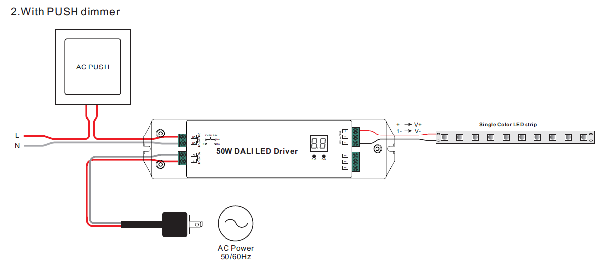
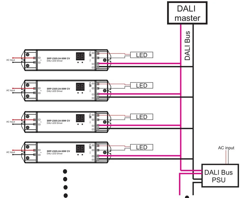
LED driver OGS DALI, TRIAC, Push to DIM, 1-10V / Adjustable output using DIP switches. LIGHT. 35mm. DALI Dimming wiring diagram. LN. N PRI. 50W LED Driver Constant Current.2 pages
Led Driver Wiring Diagram Sample - Wiring Diagram Sample led driver wiring diagram - What is a Wiring Diagram? A wiring diagram is a straightforward visual representation of the physical connections and physical layout associated with an electrical system or circuit.
2011-2012 Complete Wiring Diagram - Jeep Wrangler Forum 17.06.2020 · To-Schnizdawg you've got alot of helpful wiring info here but I can't match up my stereo's wiring color codes to those listed, I have a 2012 Wrangler Sport with very basic stereo features, no sirius, no rear sub, ect. I'm trying to find out the speaker wiring output/diagram for the gray 22 pin stereo plug in the back so I can hook up my own ...
Duet 3 Mainboard 6HC Wiring Diagram - Duet3D The ones in the wiring diagram above are correct. This is the same for the jumper block OUT7 - OUT9 that provides power to these connectors respectively (see below). CAUTION! On v0.5 prototype boards, do not connect anything to the OUT pin of the IO_5 connector, because on these boards this pin is used to signal to the Raspberry Pi. The IO_5_OUT pin is available on …
Led Driver Rcd-24-0.30w Wiring Diagram Led Driver Rcd-24-.30w Wiring Diagram. RECOM DC/DC LED Driver Series RCD Step-Down Converter Plastic Case DC/DC LED Driver 4,VmA Wire RCD/W/VREF: Recom. LED Driver. Wide Input and Output Voltage Range. Digital PWM and Analogue Voltage Dimming. Short Circuit Protected. Pinned or Wired Versions. RCD datasheet, cross reference, circuit and ...
LED Driver Compact dimming - Tridonic Dimmable built-in constant current LED Driver ... 3.1 Circuit diagram. Udriver ... To avoid the damage of the Driver, the wiring must be protected against.11 pages
GUIDE TO LED WIRING - Astro Lighting All our LED products that need a separate driver must be wired in SERIES not parallel. SERIES WIRING DIAGRAM. PARALLEL WIRING DIAGRAM ...5 pages
Driver Philips Led Bulb Circuit Diagram - Electronics ... Philips Led Tube Wiring Diagram Led Tube Light Wiring Diagram Single Light Wiring Diagram T8 Led Lam Led Fluorescent Tube Fluorescent Tube Led Fluorescent . The driver circuit divides a string of 25 leds into two sets of five one set of four and one set of six. Driver philips led bulb circuit diagram. The main component is the x rated ac ...
› TechnicalDocumentLibrary › 369613aMaestro LED+ Dimmer - Lutron Electronics Company Inc — Lutron LTEA Hi-lume 1% forward-phase LED driver — Hogeal n — ncndaI scet ne • Low-end adjustment to accommodate a wide range of bulbs. • No neutral required for retrofit applications. • Tapswitch returns load to previous level. • Can be used in single-pole, multi-location (using MA-R), or 3-way mechanical switch1 applications.
PEUGEOT Fault Codes DTC - Car PDF Manual, Wiring Diagram ... Hello nice to meet you I got problem with my R300 BT (Radio), and need R300 BT wiring diagram for opel astra K 2017 sport tourer to repair it, can you plaeas send the diagram or pins info from R300 BT wiring diagram opel. Thnx ikramidis@hotmail.com #159. Ghaly (Saturday, 12 September 2020 16:36)
arduinogetstarted.com › tutorials › arduino-rgb-ledArduino - RGB LED | Arduino Tutorial Learn how to use RGB LED with Arduino, how to connect RGB LED to Arduino, how to code for RGB LED, how to program Arduino step by step. The detail instruction, code, wiring diagram, video tutorial, line-by-line code explanation are provided to help you quickly get started with Arduino. Find this and other Arduino tutorials on ArduinoGetStarted.com.
PDF LED driver Compact dimming Driver LC 8W 180mA fixC pc SR ... (LED module) in parallel. • Secondary switching is not permitted. • Incorrect wiring can demage LED modules. • To avoid the damage of the Driver, the wiring must be protected against short circuits to earth (sharp edged metal parts, metal cable clips, louver, etc.). 3.5 Replace LED module 1. Mains off 2. Remove LED module 3. Wait for 20 ...
12v Led Circuit Diagram - U Wiring LED Light Bar Relay Wire Up At Wiring Diagram For 12V Led A wiring diagram usually gives guidance more or less the relative approach and promise of devices and terminals on the devices to support in. The forward voltage of each LED at 700mA is 298V dc.
High Power LED Driver Circuits : 12 Steps (with Pictures ... 1) power dissipation. Q2 acts as a variable resistor, stepping down the voltage from the power supply to match the need of the LED's. so Q2 will need a heatsink if there is a high LED current or if the power source voltage is a lot higher than the LED string voltage. (Q2 power = dropped volts * LED current).

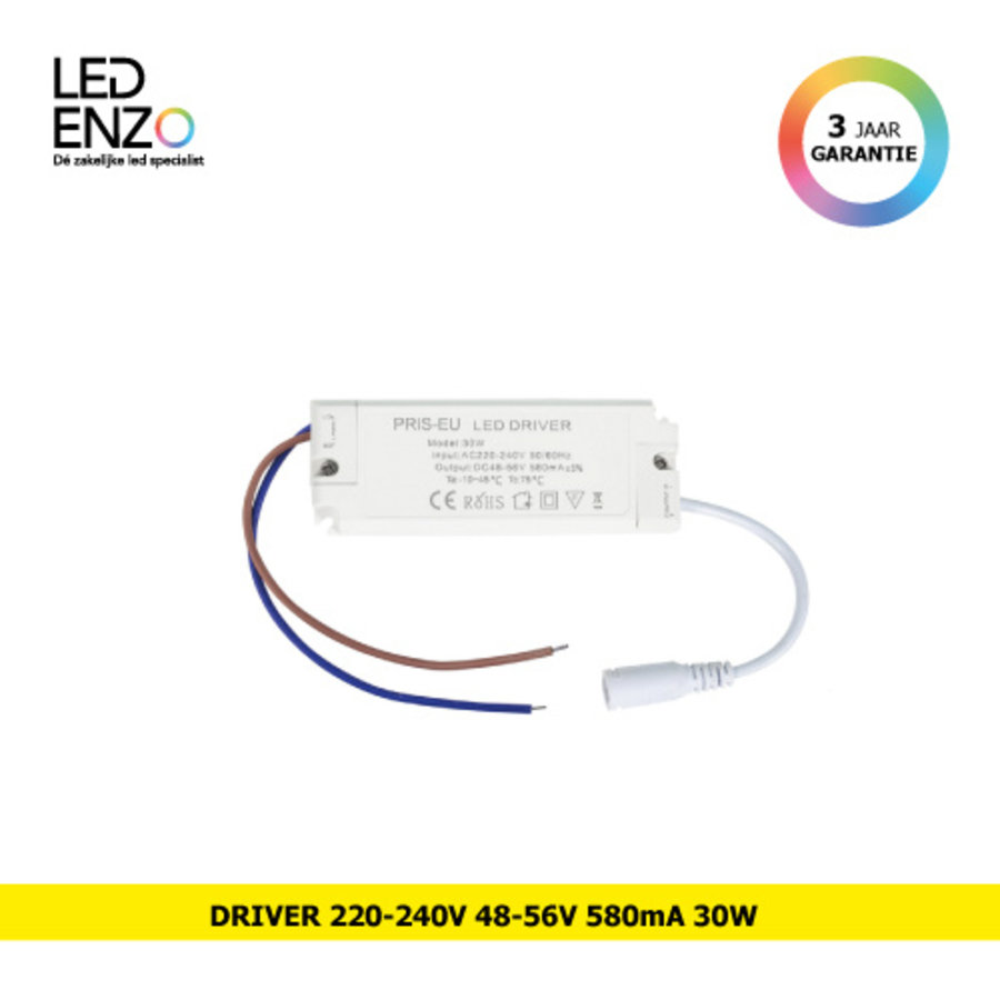
220V LED Driver Constante Stroom 300mA 240mA Uitgang 1-50W Voeding Externe Verlichting Transformator Voor LED plafondlamp
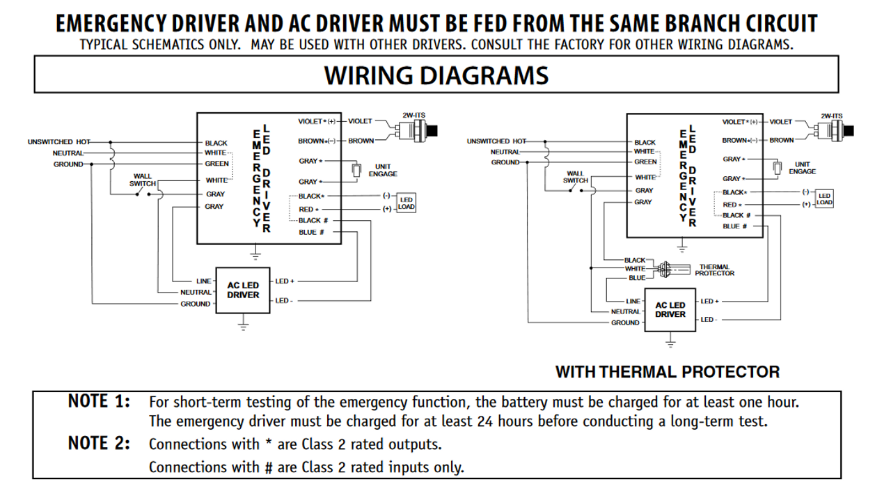
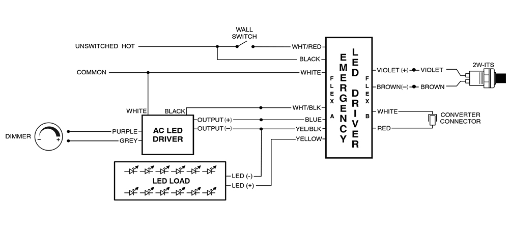
PDF PLD10M LED Battery Pack Instruction Sheet WIRING Step 5. Select correct wiring diagram to connect the emergency driver to the LED load, AC LED driver and Switch. Make sure all connections are in accordance with the National Electrical Code and any local regulations. Step 6. Install the labels "CAUTION" & "STATUS" in a visible location (see illustration 4). Step 7.
Led Lighting Wiring Diagram - Wirings Diagram There are two things that will be present in almost any Led Lighting Wiring Diagram. The first element is emblem that indicate electrical element from the circuit. A circuit is usually composed by numerous components. The other thing you will come across a circuit diagram would be lines.
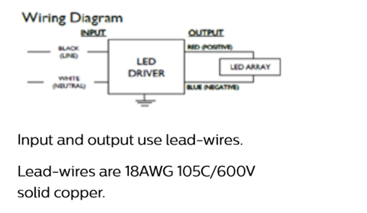
PDF LED Driver - images.philips.com 1. LED driver shall be installed inside an electrical enclosure. 2. Wiring inside electrical enclosure shall comply with 300V/90°C rating or higher. 3. Max. number of LEDs in series should not exceed 16. 4. Max. LED voltage should not exceed 54V under all operating conditions. 5. Rset can be used to adjust output current between 100 to
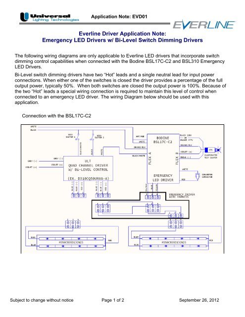
PDF Everline Driver Application Note: Emergency LED Drivers w ... The following wiring diagrams are only applicable to Everline LED drivers that incorporate switch dimming control capabilities when connected with the Bodine BSL17C-C2 and BSL310 Emergency LED Drivers. Bi-Level switch dimming drivers have two "Hot" leads and a single neutral lead for input power connections. When either one of the switches ...
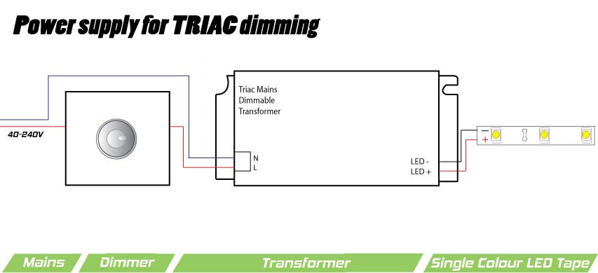
LED Dimming Driver Wiring Diagram LED Dimming Driver Wiring Diagrams. LED DRIVERS. AlconLighting.com © 2018. 2845 S. Robertson Blvd. Los Angeles, CA 90034 USA. (877) 733-5236.1 page
A Complete Guide to LED Drivers | RS Components Wiring an LED driver to mains power is straightforward. Connect the neutral and line wires to the PRI (primary) side of the driver, attaching the former to ...8 topics include: How to Connect an LED Driver to Power ⋅ How to Wire LED Drivers and Transformers ⋅ How to Test an LED ... ⋅ View full list
Emergency Led Driver Wiring Diagram - Wiring Diagram Line Fat led f1a emergency pack connection wiring diagram easy to install this model suitable for lights with external driver contact light power supply source ...
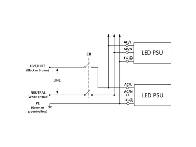
PDF Installation Manual - MEAN WELL (b)Connect the ACL wire (black or brown) of the LED power supply to Live (black or brown). (c)Connect the ACN wire (white or blue) of the LED power supply to Neutral (white or blue). Installation Manual (8)The maximum number of the LED PSUs that can be connected to a circuit breaker at 230V is shown as below.
Wiring Diagram - Cita Power LED PWXL D + TRL - TRL + D - A IN 4-6W LED Driver LED 010VD Dimming control PWXLD INSTALLATION NOTES: 1. Turn off power to the circuit prior installing. ONNETING TO LIVE POWER MAY AUSE PERMANENT DAMAGE TO THE DRIVER. 2. Use wire nuts on all connections and cap any unused wires. 3. LED string (D +/-) should be con-nected first, and must be connected
› citroen-fault-codesCITROEN Fault Codes DTC - Car PDF Manual, Wiring Diagram ... Hello nice to meet you I got problem with my R300 BT (Radio), and need R300 BT wiring diagram for opel astra K 2017 sport tourer to repair it, can you plaeas send the diagram or pins info from R300 BT wiring diagram opel. Thnx ikramidis@hotmail.com #159. Ghaly (Saturday, 12 September 2020 16:36)
Wiring Details LED Drivers - ACE LED's Wiring Details for Dimming LED Drivers. INSPIRED DESIGNS IN LED LIGHTING . 1 (800) 375-6355 / sales@aceleds.com; We have over 20 years LED Driver and electronic ballast manufacturing experience, and over 15,000,000 installation sites worldwide. When you compare you'll find that the quality, warranty and customer support of our competitively ...
PDF LED Driver + Dimmer - Kichler 40W, 60W or 100W Constant Voltage LED Driver with Integrated Dimmer for Single Gang Box Mount LED Driver + Dimmer White: Neutral Black: Line Red: + LEDs Blue: - LEDs Wiring Diagram 100W: Metal case and metal wall plate 40W & 60W: Plastic case and metal wall plate E237774 5 YEAR WARRANTY Ground (GRN) 12 or 24 VDC LED Array/Fixture Driver ...
PDF LED Dimming: What you need to know - Energy • LEDs typically need a "Driver" • Dimming an LED source can change the behavior of the Driver • LED dimming performance is determined by Driver capability and compatibility with the dimming equipment • Multiple compatibility issues are rooted in circuit level interactions between the LED Driver and dimmer
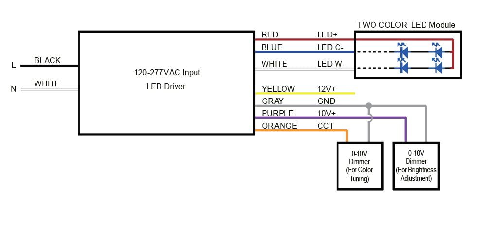
PDF Wiring Diagram Ltf WIRING DIAGRAM CAUTION: - Always follow local electrical code regulations when installing LED drivers & fixtures. - DO NOT attach 0-10V dimming wires to hot / line voltage wire. - Leave wire caps on 0-10V dimming wires when not in use to prevent short circuit.
circuitdigest.com › electronic-circuits › 2-wayHow to Connect a 2-Way Switch (with Circuit Diagram) Nov 23, 2017 · Where, 0 represents the OFF condition and 1 represents the ON condition. How to Connect 2-way Switch Wiring using Three-wire control. This is the new method to make a 2-way switch connection and it is slightly different from the two-wire control method.









0 Response to "36 led driver wiring diagram"
Post a Comment