37 chilled water air conditioning system flow diagram
Control sequences for chilled water systems - Consulting As the chilled water valve begins to open, the chilled water differential pressure transmitter senses a drop in system pressure. This sends a signal to the chilled water control panel and VFDs. The pumps are designed to operate in a parallel configuration. Currently a single pump is operating in response to water flow requirements. Chiller System Design | Designing chilled water systems Chiller System Design which including Pressure enthalpy diagrams, thermal calculations, selection of the condenser and the evaporator, piping calculations, calculation of refrigerant charge. Designing a chilled water system is the most basic of the four parts of the design and selection (compressor, condenser, evaporator, throttle valve), as long as the master of the skills, I believe that you ...
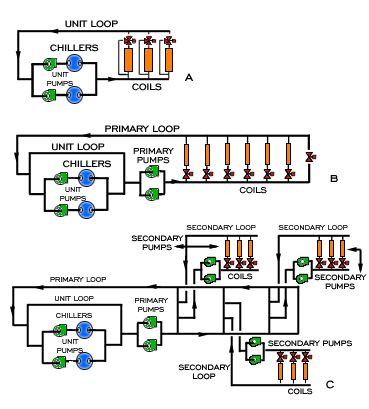
PDF Chilled Water System Presentation - HVAC Việt Nam COMMERCIAL BUILDING SERVICES FLOW THINKING 1.Low return water temperatures. 2.Robs chilled water from other coils at part load conditions. 3.Increases flow in primary piping. 4.Adds additional chillers on line. 5.Chiller performance is reduced. 3-way Valve System Deficiencies

Chilled water air conditioning system flow diagram
Central Air Conditioning System Flow Diagram | Sante Blog A Simple Air Conditioning Circuit And Cycle Diagram That You Might. Centralized Air Conditioning System Diagram Mycoffeepot Org. Flow Chart Of Proposed Control System For The Hvac. Schematic Of A Typical Chilled Water System Scientific. Introduction To Commercial Building Hvac Systems And Energy Code. Closed Loop Chilled Water System Pressure - aircondlounge From the above diagram, the chilled water inside the pipe is pressing down harder on the gate valve and the AHU that is located on the lower floor than the chiller on the upper floor. The pressure exerting on the gate valve is: Ps = ρgh. Ps = (1000) (10) (70) Ps = 700,000 Pa. Ps = 700 kPa or 7 bar or 101 psi. Flow chart of the air-cooled water chiller components ... Download scientific diagram | Flow chart of the air-cooled water chiller components. from publication: Development of a water-mist cooling system: A 12,500 Kcal/h air-cooled chiller | Global ...
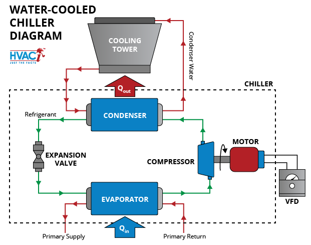
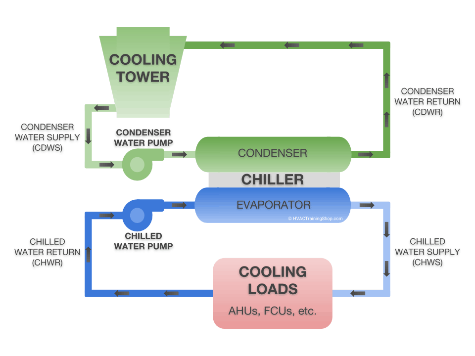
Chilled water air conditioning system flow diagram. How a Chilled Water System Works - HVAC Training Shop A chilled water system using an air-cooled chiller Water Cooled Chiller. Water-cooled chillers are almost always located inside of a building. They work almost the same way as air-cooled chillers. The difference is that they remove heat from chilled water by exhausting the heat to a second, isolated water line called the condenser water line. Air conditioning- Types, Diagram, Working, Applications Components of the air conditioning system. The basic components of the air conditioning system are, 1.Fans: For circulation of air 2. Filters: For cleaning air 3. Heating element: Heating of air (It may be an electric heater, steam, hot water) 4. Control system: It regulates automatically the amount of cooling or heating. 5. PDF HVAC Chilled Water Distribution Schemes - CED Engineering chilled water flow through the cooling coil is restricted (in response to supply air temperatures to the space) but the total quantity returned to the chiller remains constant. Figure below shows the schematic of the constant-flow rate primary system. Chilled Water Schematics - The Engineering Mindset The chilled water is generated and circulated in the primary side, the secondary loops will pull chilled water out of the header to cool the building and then dump the warm return back into the header. If the flow rate In the secondary side is low then some chilled water will flow into the secondary and some will recirculate back to the chillers.
Chiller water systems - slideshare.net ADVANTAGES OF CHILLER WATER AIR CONDITIONING SYSTEMS • THE EVAPORATOR COOLS WATER TO ABOUT 45 .THAT CHILLED WATER IS PUMPED TO COOLING COILS IN THE AREAS BEING COOLED, AND A FAN DRAWS THE AIR IN THOSE AREAS THROUGH THE CHILLED WATER COILS, COOLING THE AIR. IN COMPARISON, WITH STANDARD AIR CONDITIONING, THE EVAPORATOR COIL DIRECTLY COOLS THE AIR. Chilled Water Central Air Conditioning Plants - Bright Hub ... The chilled water flows through the cooling coil. The blower absorbs the return hot air from the air conditioned space and blows it over the cooling coil thus cooling the air. This cooled air passes over the air filter and is passed by the supply air ducts into the space which is to be air conditioned. (PDF) Air Conditioning Principles and Systems - Academia.edu Air Conditioning Principles and Systems. Tenang Sejati. Download Download PDF. Full PDF Package Download Full PDF Package. This Paper. A short summary of this paper. Schematic Diagram Of Terminal Reheat System - Air Conditioning Schematic Diagram Of Terminal Reheat System. Figure 5-8 Psychrometric chart showing properties of air in Example 5-2. tions leaving the coil and the required temperature of the supply chilled water, and (c) the cooling capacity of the coil. Solution (a) On the psychrometric chart in Fig. 5-8, four parts of return air at point 1 (24°C and 50 ...
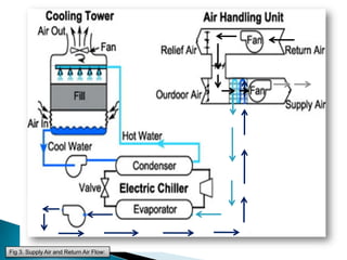
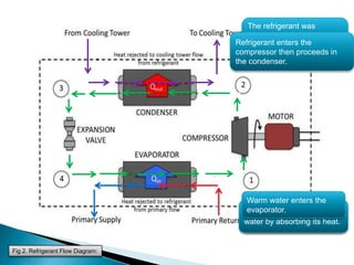
Chilled-Water Systems - Trane Order Now. Description of a chilled-water system, including the basics, design strategies, and control issues. Topics include: Vapor-compression and absorption chiller types. Air-cooled vs. water-cooled condensers. Packaged vs. split components. Equipment rating standards (ARI 550, 590, and 560) ASHRAE Standard 90.1. Water Chilled Airconditioning - SlideShare Fig 2. Refrigerant Flow Diagram: 12. Fig 3. Supply Air and Return Air Flow: 13. Advantages of Chilled Water Air-con. System: The evaporator cools water to about 45 .That chilled water is pumped to cooling coils in the areas being cooled, and a fan draws the air in those areas through the chilled water coils, cooling the air. PDF Applications Engineering Manual - Trane chiller's evaporator and condenser and their relationship to the chilled-water system. For more details on the basic operation and components of a chilled-water system, consult another Trane publication, Chilled-Water Systems, part of the Air Conditioning Clinic Systems Series (TRG-TRC016-EN). Specific application considerations for Chilled Water Systems - Engineering ToolBox Total Heat Removed The total heat removed by an air condition chilled-water system can be calculated h = 500 q dt (1) where h = total heat removed (Btu/h) q = water flow rate (gal/min) dt = temperature difference (oF) Evaporator Flow Rate The evaporator water flow rate can be calculated qe = htons 24 / dt (2) where
How Water Cooled & Air Cooled Water Chiller Unit Work || Block Diagram
PDF Chilled-Water Systems One of the Systems Series / Air ... and pipes. The water passes through the tubes of coils to cool air in an air conditioning system, or it can provide co oling for a manufacturing or industrial process. Systems that employ water chillers are commonly called chilled-water systems. When designing a chilled-wat er system, one of the first issues that must be
CHILLERS, THE AIR CONDITIONING SOLUTION YOU MAY KNOW BETTER ...
Building Drawing Software for Design Registers, Drills and ... The vector stencils library "HVAC control equipment" contains 48 HVAC symbols. Use it for drawing HVAC systems diagrams, heating, ventilation, air conditioning, refrigeration, automated building control, and environmental control design building plans and equipment layouts.
Chilled Water Air Conditioning System
PDF Drawing 47W865-5, Rev. 14, 'Flow Diagram Air Conditioning ... flow diagram reference drawrngs. 478601 47w866 47%915 47020 47b920_ -31 series series series reactor building air-conditioning air conditioning chilled water rat ts bar nuclear plant tennessee valley authority q division of engineering design 31xl thru-31x4 inspected and approved for submitted recommen knoxville 7-//-7- 85 m 47w865—5
Chiller Plant Design | Energy-Models.com
Automobile air conditioning - Wikipedia In 1954, the Nash Ambassador was the first American automobile to have a front-end, fully integrated heating, ventilating, and air-conditioning system. The Nash-Kelvinator corporation used its experience in refrigeration to introduce the automobile industry's first compact and affordable, single-unit heating and air conditioning system optional for its Nash models.

Solar Air-Conditioning Systems | IntechOpen
PDF Variable Primary Chilled Water Systems Two chillers at 500 tons each, 44°F chilled water supply, 56°F chilled water return, 12 degree delta T, and two 1000 GPM chiller pumps.) Here we see that our system is demanding 1500 GPM of flow, so we have to turn on both chillers and primary pumps. Figure 1

Chilled Water Central Air Conditioning Plants - Bright Hub ...
PDF 9.2.8 Safety Chilled Water System 9.2.8.1 Design Bases SCWS flow diagram is shown in Figure 9.2.8-1—Safety Chilled Water System Diagram. Pipe diameters for the SCWS are based on limiting the flow velocity to a range of 4 to 10 ft/second for normal modes of operation that are expected to occur frequently. Refer to Section 12.3.6.5.9 for safety chilled water system design features which
The Basics of Chillers - HVAC Investigators
Chilled-Water Cooling Basics - Surna While most people have heard of air conditioning, not everyone has heard of chilled water systems. This makes it sound scary and new. But in reality, water-chilled cooling and heating have been around since the 70s and can regularly be found in hotels, hospitals and universities, as well as high-heat environments like server farms and indoor agriculture.

Improving System Efficiency Using Series Counterflow Piping ...
PDF Understanding Chilled Beam Systems - Trane Chilled Beam Systems Overview of Chilled Beam Systems Passive chilled beams (PCB). A PCB consists of a fin-and-tube heat exchanger, contained in a housing (or casing), that is suspended from the ceiling (Figure 1). Chilled water passes through the tubes. Warm air from the space rises toward the ceiling, and the air surrounding the chilled beam is

SciELO - Brasil - Assessing the energy performance of VAV and ...
Chilled Water Air Conditioning Principles And Applications How Chilled Water Air Conditioning Works. Chiller. The chiller is the section of the system where an exchange of heat occurred between the water that goes to the building and the evaporator. The water leaves the chilled water evaporator at 45°F or 7°C. This chilled-water is then circulated through the entire building by the use of a pump.

Management of air-conditioning systems in residential ...
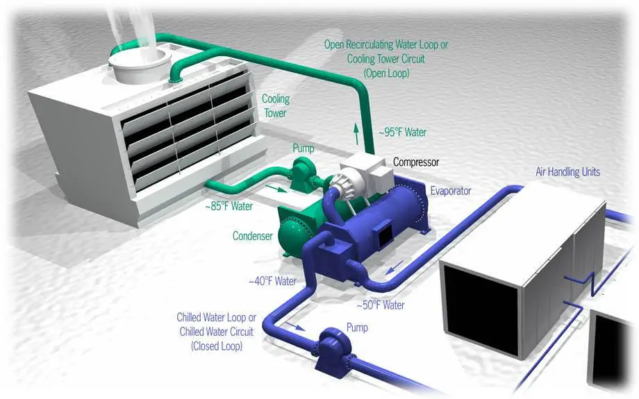
Schematic of a typical chilled-water system. | Download ... Figure 1 shows the schematic of typical chilled-water ventilation and air-conditioning system for commercial buildings with three main components: air handling unit, chiller and cooling tower.

Energy Miser: For Energy-Efficient Water Cooling, Raise ...
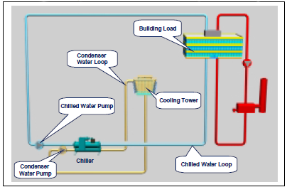
Chiller Application Guide - Daikin Applied Basic System Figure 1 shows a basic chilled water system with connected loads. The system consists of a chiller, cooling tower, building cooling load, chilled water and condensing water pumps and piping. This section will review each of the components. Chiller Basics The chiller can be water cooled or air cooled.

Optimal Operation Strategies for a Large Multi-Chiller System ...
PDF Optimizing Pumping Schemes In Air‐Conditioning Chilled water is pumped at a constant flow rate which is independent of the cooling load During part load conditions, which occurs op to 80% of the time, three way control valves at cooling coils are used to bypass the chilled water back to return line Chilled water mixes with return water from the cooling coils and this results in lower ...

INSTALLATION OF AIR CONDITIONING SYSTEM * Archi-Monarch
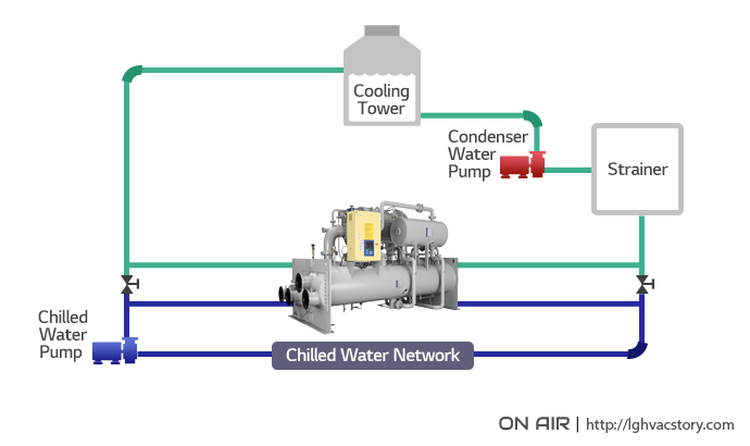
Chilled Water System: Components, Diagrams & Applications Chilled water system diagram (photos) A chilled water system can be separated into two loops; a) chilled water loop and b) condenser water loop. The chilled water loop starts with the chiller followed by the AHUs and the chilled water pump (CHWP) before returning back to the chiller.

Schematic diagram of the investigated central air ...
Flow chart of the air-cooled water chiller components ... Download scientific diagram | Flow chart of the air-cooled water chiller components. from publication: Development of a water-mist cooling system: A 12,500 Kcal/h air-cooled chiller | Global ...

Cooling and Chilled Water Systems
Closed Loop Chilled Water System Pressure - aircondlounge From the above diagram, the chilled water inside the pipe is pressing down harder on the gate valve and the AHU that is located on the lower floor than the chiller on the upper floor. The pressure exerting on the gate valve is: Ps = ρgh. Ps = (1000) (10) (70) Ps = 700,000 Pa. Ps = 700 kPa or 7 bar or 101 psi.

14 Chilled water system ideas | water systems, hvac ...
Central Air Conditioning System Flow Diagram | Sante Blog A Simple Air Conditioning Circuit And Cycle Diagram That You Might. Centralized Air Conditioning System Diagram Mycoffeepot Org. Flow Chart Of Proposed Control System For The Hvac. Schematic Of A Typical Chilled Water System Scientific. Introduction To Commercial Building Hvac Systems And Energy Code.
Commercial Library

Air conditioning- Types, Diagram, Working, Applications

What is Air Conditioning System? Diagram, Applications - ETechnoG

58 Chiller ideas | refrigeration and air conditioning, hvac ...
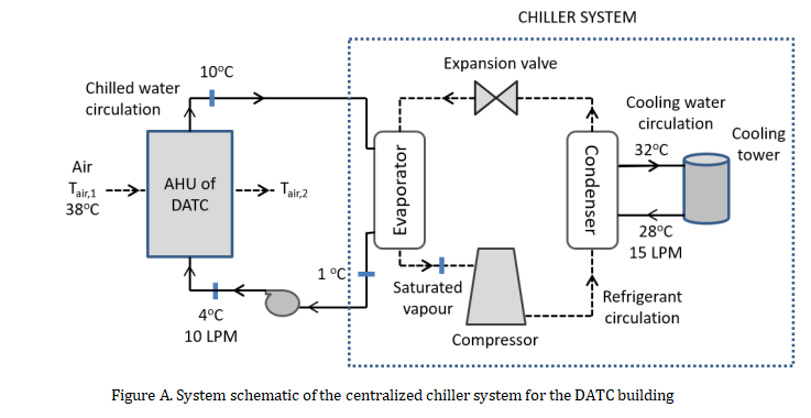
The DATC building houses a large hall for | Chegg.com
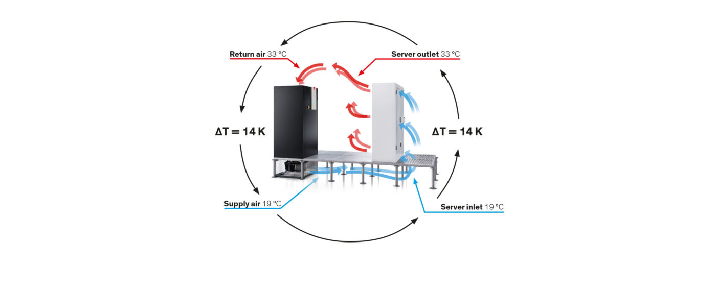
Delta T – The air-side temperature difference | STULZ

Ocean Breeze AC
BEIJING SUNDA SOLAR ENERGY TECHNOLGOY CO., LTD.
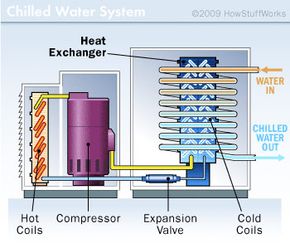
How Air Conditioners Work: Chilled-water and Cooling-tower AC ...
What is HVAC System ? | HVAC system working Principle
Water Chilled Airconditioning

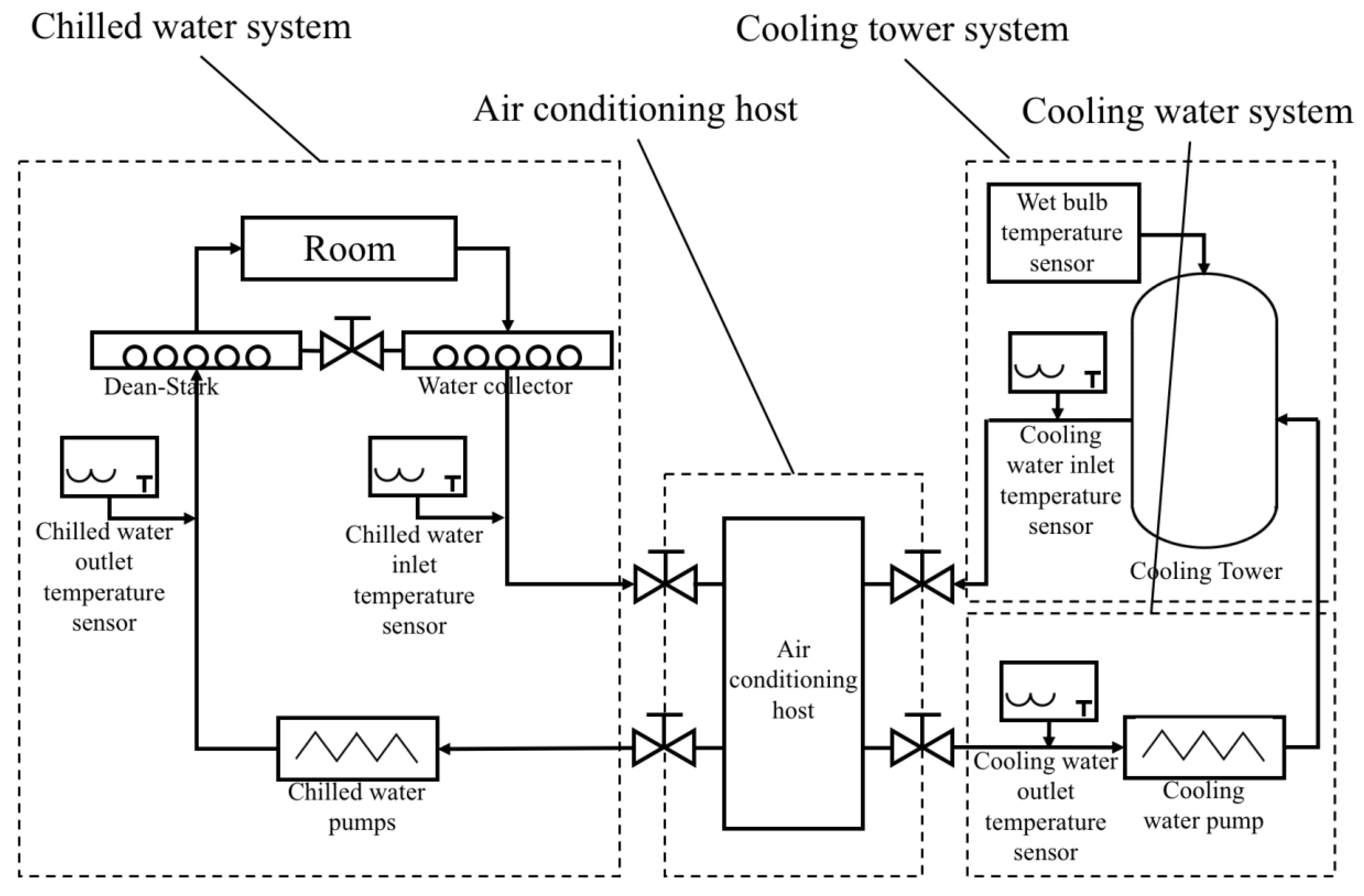
A schematic diagram of the chilled-water air conditioning ...
Water Chilled Airconditioning
Energies | Free Full-Text | Carbon and Water Footprint of ...
Business Energy Advisor | Electric Chillers
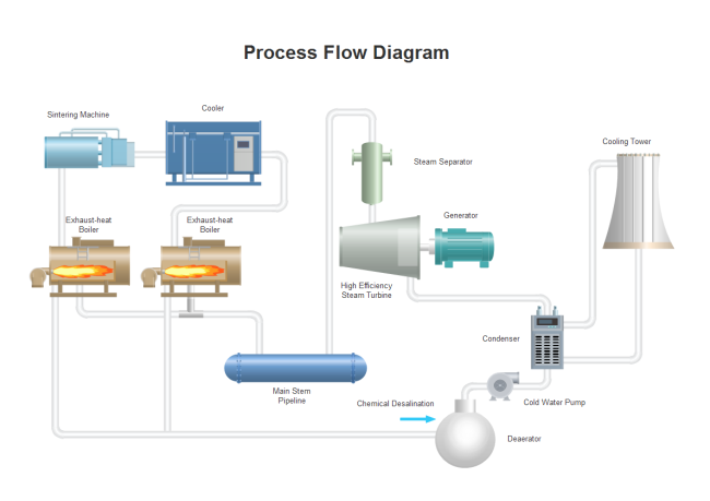
Cooling Process Flow Diagram | Free Cooling Process Flow ...
Energies | Free Full-Text | Research on Key Parameters ...

How a Chiller, Cooling Tower and Air Handling Unit work ...
How a Chilled Water System Works | HVAC Training Shop
Water Chilled Airconditioning

illustrates the schematic of the proposed air-conditioning ...
0 Response to "37 chilled water air conditioning system flow diagram"
Post a Comment