38 how to use moody diagram
Moody Diagram - Friction Loss | Application | nuclear ... Example: Moody Diagram. Using the Moody diagram, determine the friction factor (f D) for fluid flow in a pipe of 700mm in diameter with a Reynolds number of 50 000 000 and an absolute roughness of 0.035 mm. Solution: The relative roughness is equal to ε = 0.035 / 700 = 5 x 10⁻⁵.Using the Moody Chart, a Reynolds number of 50 000 000 intersects the curve corresponding to a relative roughness of ... Moody's Friction Factor - an overview | ScienceDirect Topics The Weymouth equation, however, is of use in designing gas distribution systems in that there is an inherent safety in over predicting pressure drop (Maddox and Erbar, 1982). In practice, the Panhandle equations are commonly used for large-diameter, long pipelines where the Reynolds number is on the flat portion of the Moody diagram.
PDF Pipe Flow-Friction Factor Calculations with Excel Weisbach equation, it is more convenient to use equations for the Moody friction factor, f, rather than a graph like the Moody diagram. There are indeed equations available that give the relationships between Moody friction factor and Re & ε/D for four different portions of the Moody diagram. The four portions of the Moody diagram are: i ...
How to use moody diagram
PDF Lecture 7—Friction factors - Kent State University The first guy to do this was Lewis Moody, in 1944. Moody was a "sanitation engineer", and as a result, his diagram attempts to talk about how big a pump you have to put on one end of a pipe to make water flow given roughness in the pipe. This results in the first curiosity in the Moody diagram—the Reynolds number uses Moody Chart for Estimating Friction Factors - EngineerExcel Moody Chart for Estimating Friction Factors A Moody Chart (or Moody Diagram) is used to estimate the friction factor for fluid flow in a pipe. The chart represents friction factor as a function of Reynolds number and the ratio between internal pipe roughness and pipe diameter, or relative roughness, ε/D. Contents What is a Moody Chart Used for? Moody Diagram - an overview | ScienceDirect Topics The friction factor (f) can be calculated from the Moody diagram (chart) using the Reynolds number (Re = ρ Dv / μ) and the effective roughness (ε / D), where μ is the dynamic viscosity of the fluid (kg/m s) and ε is the casing roughness height or absolute roughness (mm). The Moody diagram covers all types of single-phase flow regimes: laminar, transitional and completely turbulent flows (Dougherty et al. 1985).
How to use moody diagram. Moody Chart or Moody Diagram - The Engineering Concepts Moody Chart or Moody Diagram In Fluid Mechanics, the Moody chart or Moody diagram is a graph which relates the Darcy-Weisbach friction factor ( fD ) , Reynolds number (Re), and surface roughness for fully developed flow in a circular pipe. It can be used to predict pressure drop or flow rate down such a pipe. Moody Diagram - File Exchange - MATLAB Central MOODY (UNITS,PAPER,NAME) generates a four axis, publication quality Moody diagram as a PAPER size portable document format file NAME with UNITS. Default units are IMPERIAL. If units are SI, the default paper size is A4. If units are IMPERIAL, the default paper size is LETTER. The default file name is MOODY.PDF. Moody Chart Calculator - Engineering Projects Download the free Moody Chart Calculator app from Google Play here . Learn more about the Moody Chart Calculator here . Moody diagram - Calculation of friction coefficients ... The Moody diagram The friction factor is used to calculate the pressure drop due to the flow of a fluid in a pipe. It represents the interaction in between the fluid and the pipe. There are different ways to calculate it, one can be graphical, using a Moody graph. Note that the friction factor used here is
How To Use Moody Chart - gfecc.org Diagram Moody Chart Darcy Weisbach Equation Darcy Friction; Moody Diagram Moody 1944 Reproduced By Permission Of; Moodys Friction Factor Calculator Towards Open Science; Fanning Friction Factor Wikipedia; Fluid Mechanics Turbulent Flow Moody Chart; Solved Use The Moody Chart To Determine The Pressure Loss; Moody Diagram Moody 1944 Reproduced By ... Moody Chart, Moody's Table Engineers Edge The Moody chart or Moody diagram is a graph in non-dimensional form that relates the Darcy-Weisbach friction factor f D, Reynolds number Re, and relative roughness for fully developed flow in a circular pipe. It can be used for working out pressure drop or flow rate down such a pipe. Click on Chart image to get larger Moody Chart. Turbulent Flow: Moody Chart [Fluid Mechanics #41] - YouTube An introduction to the famous Moody Chart! We use the Moody Chart often to estimate frictional factors. To download the notes I use for these videos, please ... What is Moody Diagram - Definition - Thermal Engineering Example: Moody Diagram. Determine the friction factor (f D) for fluid flow in a pipe of 700mm in diameter that has the Reynolds number of 50 000 000 and an absolute roughness of 0.035 mm.. Solution: The relative roughness is equal to ε = 0.035 / 700 = 5 x 10⁻⁵.Using the Moody Chart, a Reynolds number of 50 000 000 intersects the curve corresponding to a relative roughness of 5 x 10⁻⁵ at a ...
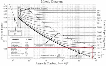
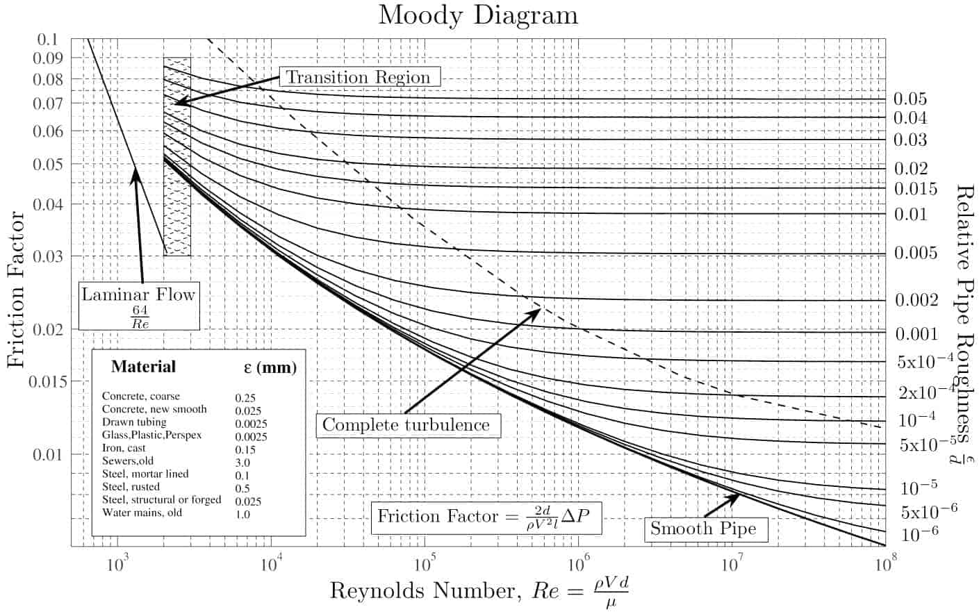
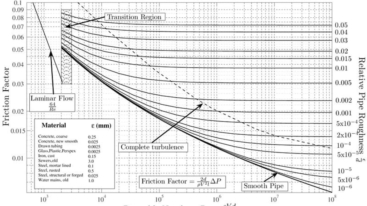
Write a short note on Moodys Diagram The Moody chart or Moody diagram is a graph in non-dimensional plot that relates the Darcy Weisbach friction factor (f), Reynolds number (Re) and Relative Roughness parameter (ϵ/d) for fullydeveloped flows in a circular pipe. Water Piping System Design Size Calculations - Part-7 ... Moody friction factor will be used as another input for the D'arcy-Weisbech equation which is used for calculating the final pressure drop of the piping system design calculation example.The Moody's factor can either be calculated by using Colebrook equation or by using Moody diagram. Moody diagram - Calculation of friction coefficients ... The Moody diagram The friction factor is used to calculate the pressure drop due to the flow of a fluid in a pipe. It represents the interaction in between the fluid and the pipe. There are different ways to calculate it, one can be graphical, using a Moody graph. Moody chart - Wikipedia In engineering, the Moody chart or Moody diagram (also Stanton diagram) is a graph in non-dimensional form that relates the Darcy-Weisbach friction factor f D, Reynolds number Re, and surface roughness for fully developed flow in a circular pipe. It can be used to predict pressure drop or flow rate down such a pipe.
Fluid Mechanics
Friction Factor & Moody Chart - The Engineering Concepts Friction Chart or Moody Chart. The value of f, Darcy friction factor is taken from Moody Diagram. The friction factor for laminar flow is calculated by dividing 64 by the Reynold's number. Friction factor (for laminar flow) = 64 / Re ; This is for circular pipes. For Non-Circular Pipes; f=k/Re ; where k lies between 48 to 96.
Basic Fluid Mechanics Major losses, Colebrook-White equation ...
PDF Moody Diagram - Essom MOODY DIAGRAM Friction factors for any type and size of pipe. (From Pipe Friction Manual, 3rd ed., Hydraulic Institute, New York, 1961) O O = J uopeJ UO!IOUJ uoeqs!êM-Á0Jea S C o i. (ww u! a 'wul u! 3) = J ssauuôno' Title: Microsoft Word - Moodies diagram.doc Author: Administrator
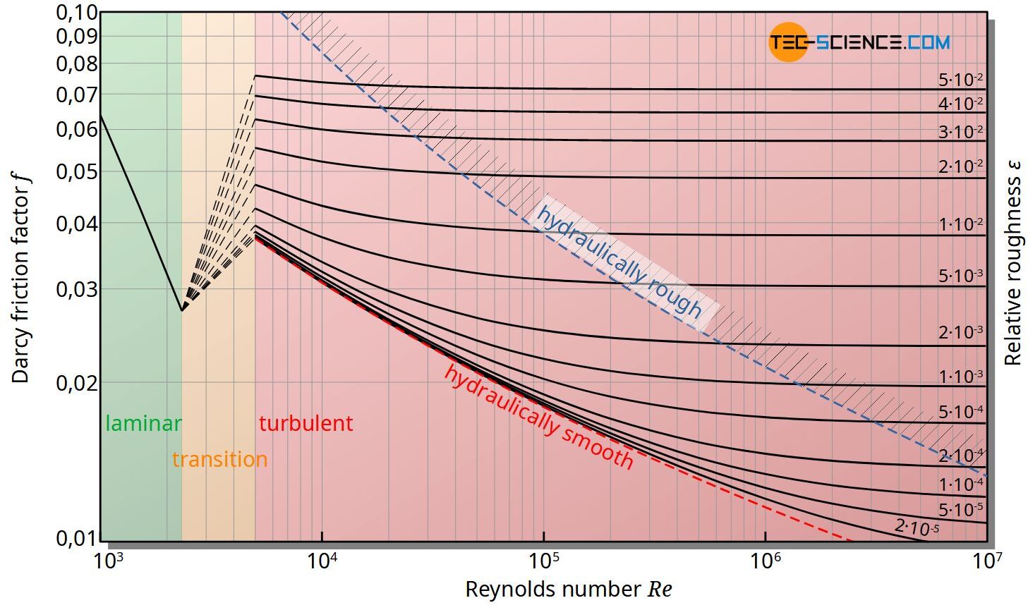
Moody chart (diagram) - tec-science
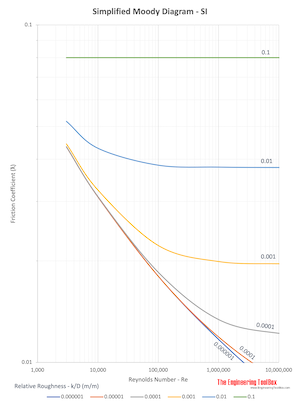
Moody Diagram - Engineering ToolBox SI based Moody Diagram The Moody friction factor - λ (or f) - is used in the Darcy-Weisbach major loss equation. The coefficient can be estimated with the diagram below: If the flow is transient - 2300 < Re < 4000 - the flow varies between laminar and turbulent flow and the friction coefiicient is not possible to determine.

Describe the appearance of laminar flow and turbulent flow ...
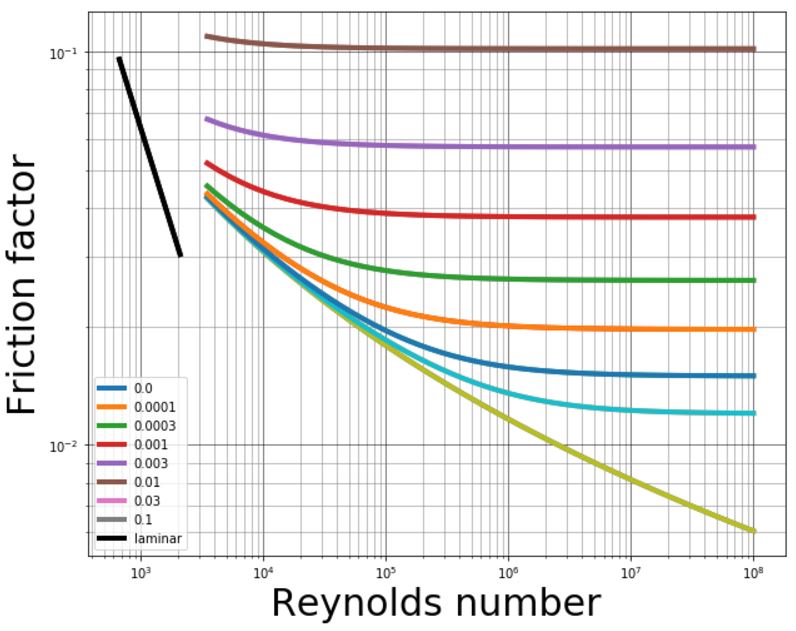
How do I complete my code to plot the Moody Chart? I was told to create an array of roughnesses and plug them into the colebrook equation. Then, plot the moody. I'm just not sure how to go about that.
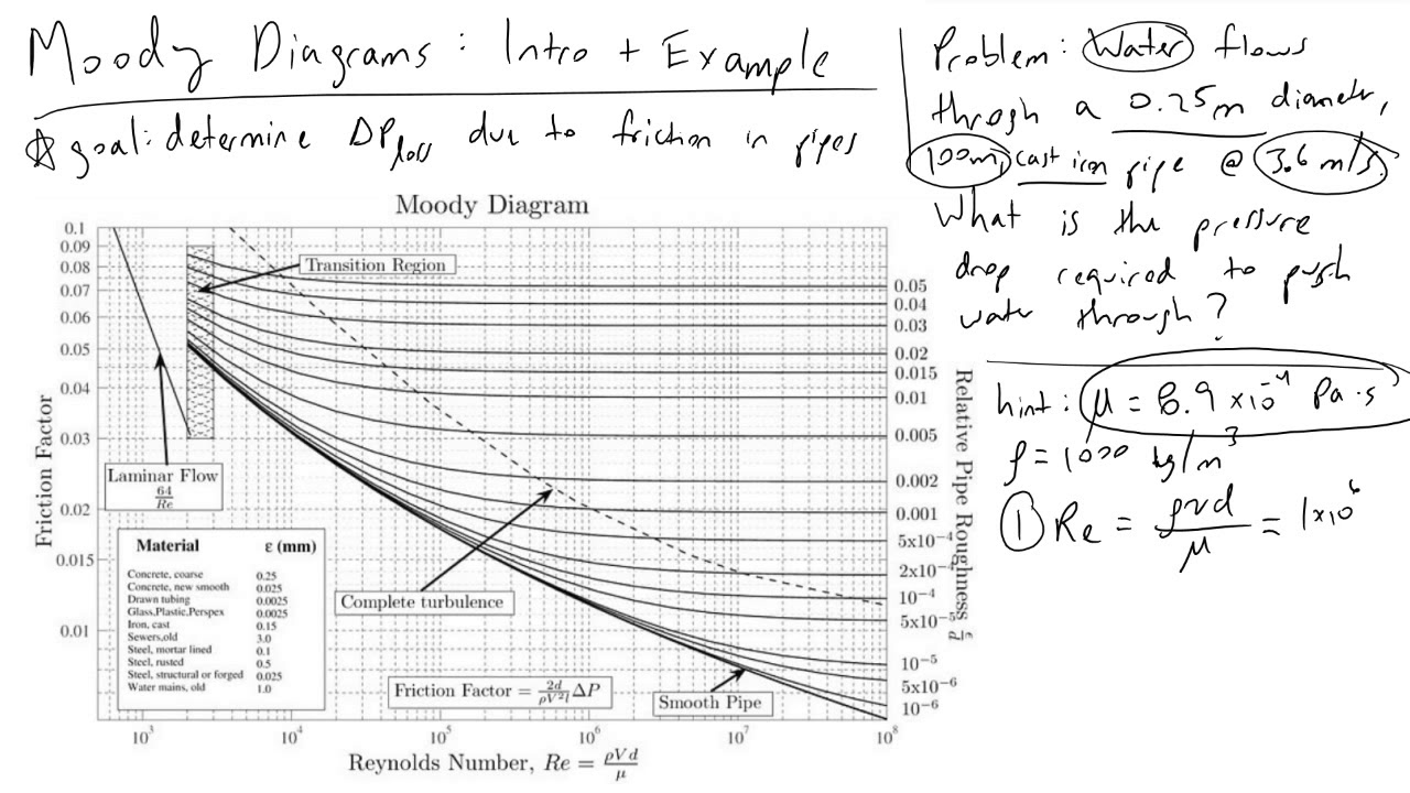
Moody Diagrams Intro and Example
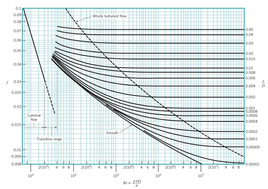
Moody Diagram - UNLP 10 3 10 4 10 5 10 6 10 7 10 8 10 −2 10 −1 8 9 1.2 1.4 1.6 1.8 2 2.5 3 3.5 4 4.5 5 5.5 6 7 6 7 8 2 3 4 5 6 7 8 2 3 4 5 6 7 8 2 3 4 5 6 7 8 2 3 4 5 6 7 8 2 3 4 5 6 ...
How to Read a Moody Chart (Moody Diagram) - Owlcation
Friction Factor Calculation in Excel - LEV ... - LEV Central But now, thanks to the miracle of Excel, you can use your trusty old Moody Diagram AND have an instant answer at the push of a button. The Excel spreadsheet linked at the bottom of this page contains the Churchill Correlation equations for the friction factor along with a plot that has been carefully overlaid on top of a standard Moody diagram ...
Experiment #4: Energy Loss in Pipes – Applied Fluid Mechanics ...
Moody Diagram | Software Configuration Tips from an Idiot Moody Diagram. I appear to be making a career out of re-drawing old diagrams which the department has been photocopying since 1968 and now are a bit tatty. One of my latest attempts was to produce a Moody Diagram in SI Units on A4 paper. The code is available elsewhere but for your viewing pleasure I include the diagram here.

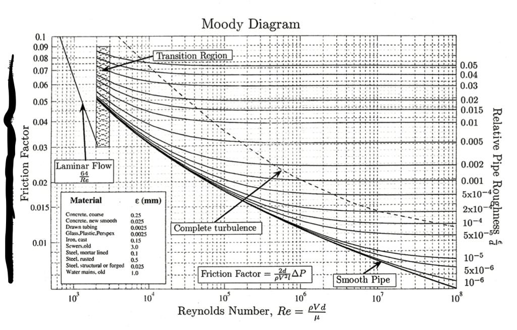
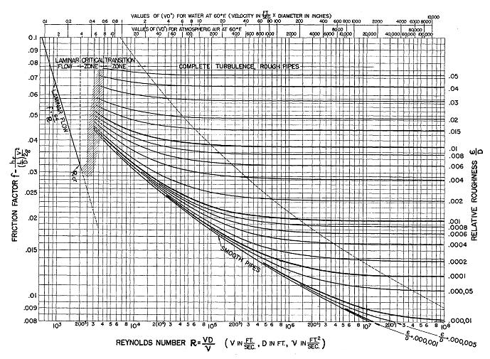
Moody Chart for Darcy Friction Factor Estimate (Source: Moody ...
Relative Roughness of Pipe | Calculation | nuclear-power.com The Moody chart (also known as the Moody diagram) is a graph in the non-dimensional form that relates the Darcy friction factor, Reynolds number, and the relative roughness for fully developed flow in a circular pipe. The relative roughness is equal to ε = 0.035 / 700 = 5 x 10 -5. Using the Moody Chart, a Reynolds number of 50 000 000 ...

Using a Moody Chart
Using a Moody Chart - YouTube Explains how to read a Moody chart for determining frictional factors in pipe flow problems. Made by faculty at the University of Colorado Boulder, Departmen...

Moody Diagram - File Exchange - MATLAB Central
How to Read a Moody Chart (Moody Diagram) - Owlcation Using a straight edge, follow the point straight left, parallel to the x axis, until you reach the far left side of the chart. Read off the corresponding friction factor. Calculate the energy losses knowing the friction factor. Calculate a new velocity and Reynolds Number. Compare your new Reynolds Number with your previous value.
What is Moody Diagram - Definition
Solving the Colebrook Equation for Friction Factors ... The work of Moody, and the Moody Diagram on page 6 72 of the published transactions, has become the basis for many of the calculations on friction loss in pipes, ductwork and flues. While there are modified versions of the original Moody Diagram, I will strive to use the original diagram as the basis for terminology used here.
What is Moody Diagram - Definition
Moody Chart Calculator - EngineerExcel A Moody Chart (or Moody Diagram) is a diagram used in the calculation of pressure drop or head loss due to friction in pipe flow. More specifically, a Moody diagram is used to find the friction factor for flow in a pipe. Friction factor is plotted vs. Reynolds number and relative roughness on a Moody chart.

Friction Factor - an overview | ScienceDirect Topics
Moody Diagram - an overview | ScienceDirect Topics The friction factor (f) can be calculated from the Moody diagram (chart) using the Reynolds number (Re = ρ Dv / μ) and the effective roughness (ε / D), where μ is the dynamic viscosity of the fluid (kg/m s) and ε is the casing roughness height or absolute roughness (mm). The Moody diagram covers all types of single-phase flow regimes: laminar, transitional and completely turbulent flows (Dougherty et al. 1985).
How to Read a Moody Chart (Moody Diagram) - Owlcation
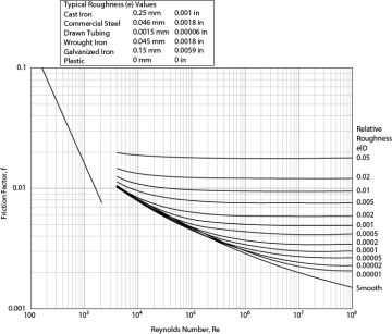
Moody Chart for Estimating Friction Factors - EngineerExcel Moody Chart for Estimating Friction Factors A Moody Chart (or Moody Diagram) is used to estimate the friction factor for fluid flow in a pipe. The chart represents friction factor as a function of Reynolds number and the ratio between internal pipe roughness and pipe diameter, or relative roughness, ε/D. Contents What is a Moody Chart Used for?
What are the ordinate and abscissa in a Moody diagram for ...
PDF Lecture 7—Friction factors - Kent State University The first guy to do this was Lewis Moody, in 1944. Moody was a "sanitation engineer", and as a result, his diagram attempts to talk about how big a pump you have to put on one end of a pipe to make water flow given roughness in the pipe. This results in the first curiosity in the Moody diagram—the Reynolds number uses
Lab 01 - Moody Diagram & Intro to Mathcad (w jpegs)

Moody chart - Wikipedia
Colebrook Equation

Moody chart - File Exchange - MATLAB Central
SOLVED:Moody Diagram 0.09 0.08 0.07 0.06 Tansition Region ...

Moody diagram - Calculation of friction coefficients graphically

Discussion of “Transformation of Moody Diagram” | Journal of ...

Pipe Friction Calculation for Fluid Flow in a Pipe
Moody chart - Big Chemical Encyclopedia
Solved] Use the Moody diagram to find the shear stress and ...
19.3 Frictional Pipe Flow | Process Fluid Mechanics | InformIT

Moody Diagram
Fluid Mechanics Review — AguaClara Textbook v1.2.6 documentation
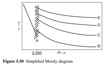
Get Answer) - Given an over-simplified Moody diagram (Fig ...
Which Head Loss Equation is Right?

Friction diagrams – Dr Ove Bratland Systems Pte. Ltd.
Understanding the Darcy-Weisbach Equation - Sprinkler Age
Pipe flow pressure drop
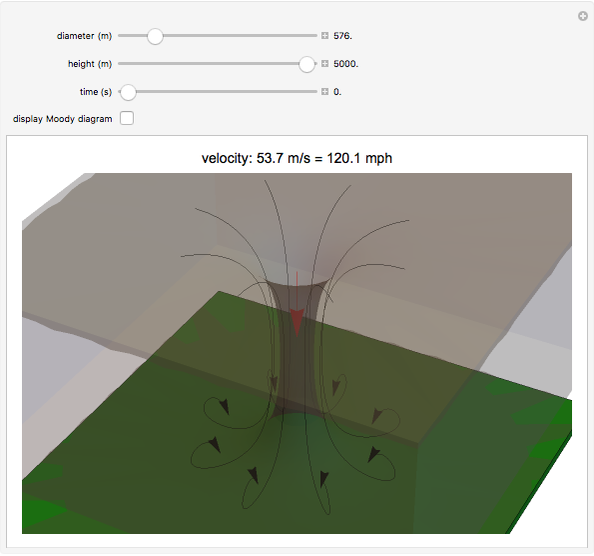
Downbursts and the Moody Diagram - Wolfram Demonstrations Project
Moody Chart, Moody's Table Engineers Edge
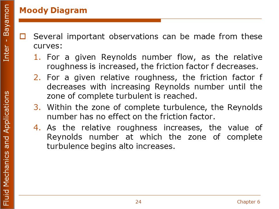
Fluid Mechanics and Applications MECN ppt download

Friction diagrams – Dr Ove Bratland Systems Pte. Ltd.

Pin on hhjj
0 Response to "38 how to use moody diagram"
Post a Comment