38 phase locked loop block diagram
Phase Locked Loops (PLL) and Frequency Synthesis Phase Locked Loop Block Diagram ÖN Ref Div Loop Filter VCO Phase Locked Loops (PLL) are ubiquitous circuits used in countless communication and engineering applications. Components include a VCO, a frequency divider, a phase detector (PD), and a loop lter. Niknejad PLLs and Frequency Synthesis Phase Locked Loops PDF Phase Locked Loop Control of Inverters in a Microgrid C. Three-phase PLL design A block diagram displaying the functional components of a generic PLL is shown in Figure 3. For small deviations, standard simplifying assumptions [7] allow the PLL to be modeled according to the linear block diagram of Figure 4, where t is the phase of the measured voltage and p is the phase estimate given by the PLL.
0.1 MHz to 500 MHz Clock Generator with Integer N PLL Data ... Low frequency phase-locked loops (PLLs) Frequency translation . Oven controlled crystal oscillator ( OCXO) frequency multipliers . Phase lock clean high frequency references to 10 MHz equipment . FUNCTIONAL BLOCK DIAGRAM Figure 1. GENERAL DESCRIPTION . Together with an external loop filter and a voltage controlled crystal oscillator ( VCXO), the
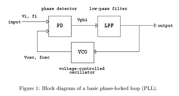
Phase locked loop block diagram
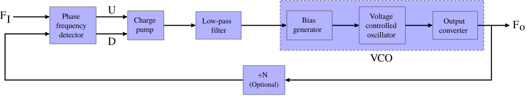
Phase Locked Loop System Working and Applications The figure shows the block diagram of the phase locked loop system in FM transmitter that consists of different blocks such as a crystal oscillator, phase detector, loop filter, voltage controlled oscillator (VCO), and frequency divider. Crystal Oscillator It is the most important part of the phase locked loop system. Phase Locked Loop Operating Principle and Applications BASIC DIAGRAM OF PHASE LOCKED LOOP Block Diagram And Working Principle Of PLL The phase-locked loop consists of a phase detector, a voltage controlled oscillator and, in between them, a low pass filter is fixed. The input signal 'Vi' with an input frequency 'Fi' is conceded by a phase detector. Phase Locked Loop (PLL) - its Operation, Characteristics ... Block Diagram A PLL operates like a typical feedback system. It updates the output frequency of VCO until it matches the frequency of the input signal i.e. in sync with the input signal. Concept Of Operation The operation of Phase locked loop is based on the phase difference between the input and output signals.
Phase locked loop block diagram. LECTURE 430 – PHASE-LOCKED LOOPS PHASE-LOCKED LOOPS Components of a Phase-Locked Loop Function of a phase-locked loop is to lock the frequency of a VCO to an input frequency. Block diagram: Phase FrequencyVo Detector (PFD) LPF VCO Input Frequency fin fosc MPLL09 Output Voltage What Is a Phase-Locked Loop (PLL)? - NI A phase-locked loop (PLL) is a feedback circuit designed to allow one circuit board to synchronize the phase of its on board clock with an external timing signal. PLL circuits operate by comparing the phase of an external signal to the phase of a clock signal produced by a voltage controlled crystal oscillator (VCXO). PDF Lecture 070 - Digital Phase Lock Loops (Dpll) Block diagram: x(t) PFD QA QB VDD Cp I1 I2 S1 S2 VCO y(t) Fig. 2.2-20 The charge pump and capacitor Cp serve as the loop filter for the PLL. The charge pump can provide infinite gain for a static phase shift. SAM D21/DA1 Family Data Sheet SAM D21/DA1 Family Low-Power, 32-bit Cortex-M0+ MCU with Advanced Analog and PWM Features • Processor – Arm® Cortex®-M0+ CPU running at up to 48 MHz • …
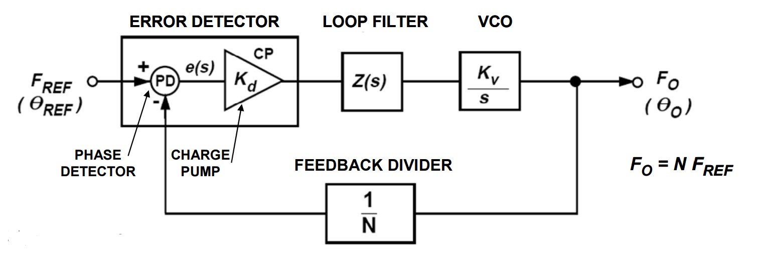
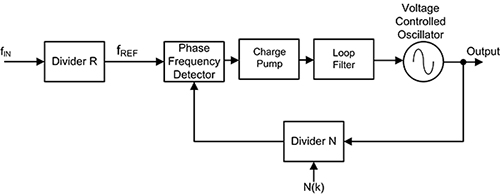
Predicting the Phase Noise and Jitter of PLL-Based ... The block diagram of a PLL operating as a frequency synthesizer is shown in Figure 1 [8]. It consists of a reference oscillator (OSC), a phase/frequency detector (PFD), a charge pump (CP), a loop filter (LF), a voltage-controlled oscillator (VCO), and two frequency dividers (FDs). The PLL is a feedback loop that, wh en in lock, forces Phase-Locked Loop(PLL)-Block Diagram and Application – GeeksGod Jul 10, 2021 · Phase-Locked Loop (PLL)-Block Diagram and Application Analog Electronics 0 Comments A Phase-Locked Loop can be designed to lock to the incoming signal despite the noise. The phase of the output signal is related to the phase of the input signal. First used in 1930. Block Diagram of Phase-Locked Loop: The main building blocks of PLL Demo: Phase Locked Loop - MathWorks Demo: Phase Locked Loop. This demo shows the executable specifications and design with simulation capabilities of Simulink. It highlights: 1. Creating conceptual models of signal processing systems and running simulations. 2. Adding finite state machines to the design. 3. Creating models of physical components (e.g. circuitery) 4. PLL Synthesizers - Analog Devices The synthesizer works in a phase-locked loop (PLL), where a phase/frequency detector (PFD) compares a fed back frequency with a divided-down version of the reference frequency (Figure 1). ... Block diagram of a PLL. Frequency is scaled by the use of counters.
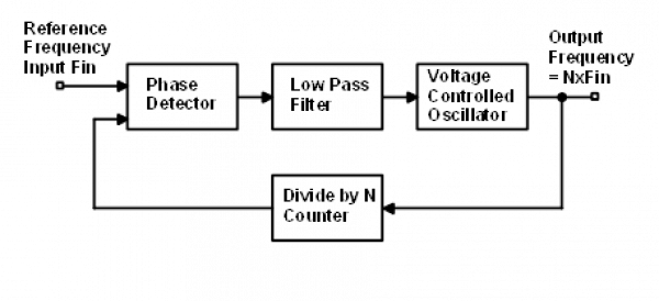
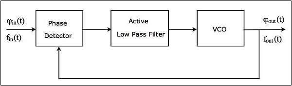
Simulating phase locked loops with MATLAB - aaron.scher Below is a block diagram of a Type 1 PLL: Below is the MATLAB program that simulates the above phase locked loop. ... %analog phase locked loop (Type 2 with multiplier and low-pass filter) % %Written by Aaron Scher % %The reference signal is a simple sinusoid. The output should be a sinusoid Phase Locked Loop - an overview | ScienceDirect Topics The block diagram of a phase locked loop. (11.35) f ref = f d = F out N or (11.36) F out = N f ref Since the divisor N is easy to change in practice, a wide range of frequencies can be generated from a single reference. These frequencies have the accuracy and long-term stability of the original reference. Phase Locked Loop IC - Tutorialspoint Block Diagram of PLL A Phase Locked Loop (PLL) mainly consists of the following three blocks − Phase Detector Active Low Pass Filter Voltage Controlled Oscillator (VCO) The block diagram of PLL is shown in the following figure − The output of a phase detector is applied as an input of active low pass filter. Introduction to phase-locked loop system modeling Introduction to phase-locked loop system modeling Introduction Phase-locked loops (PLLs) are one of the basic building blocks in modern electronic systems. They have been widely used in com-munications, multimedia and many other applications. The theory and mathematical models used to describe PLLs are of two types: linear and nonlinear ...
Activity: The Phase Locked Loop - ADALM2000 [Analog Devices Wiki]
PDF Digital Phase Locked Loop - Electrical & Computer Engineering A phase locked loop is a device which generates a clock and sychronizes it with an input signal. ... Figure 1: DPLL Block Diagram 7. 2.2.1 Voltage Controlled Oscillator Generates a digital clock. The frequency of the clock generated is controlled by one or more voltage inputs.

Phase Locked Loop Operating Principle(हिन्दी )
Phase-locked loop - Wikipedia A phase-locked loop or phase lock loop (PLL) is a control system that generates an output signal whose phase is related to the phase of an input signal. There are several different types; the simplest is an electronic circuit consisting of a variable frequency oscillator and a phase detector in a feedback loop.The oscillator generates a periodic signal, and the phase detector compares the ...

General block diagram of ADPLL Beginning of all digital phase ...
Phase Locked Loop (PLL) for Symbol Timing Recovery ... A Phase Locked Loop (PLL) is a device used to synchronize a periodic waveform with a reference periodic waveform. It is an automatic control system in which the phase of the output signal is locked to the phase of the input reference signal. In the context of carrier phase synchronization, we talk about tracking the phase of an input reference ...
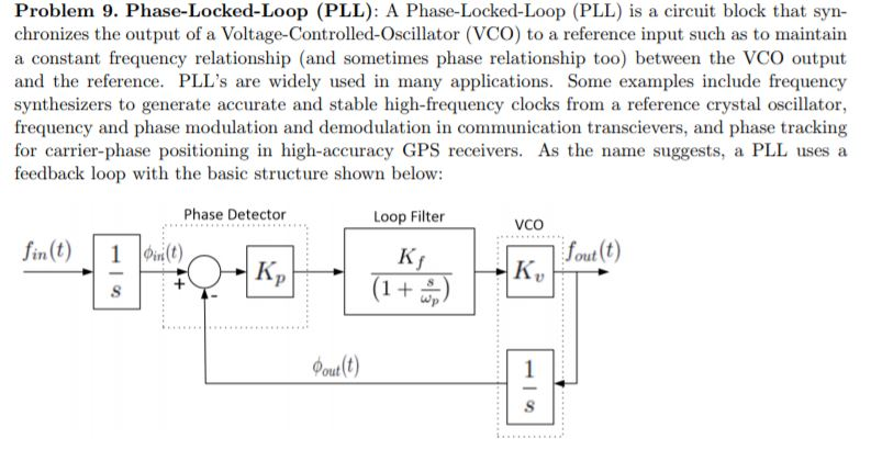
Solved Problem 9. Phase-Locked-Loop (PLL): A | Chegg.com
Phase Locked Loop Tutorial - Block Diagrams - Electronics ... Block Diagrams Phase Locked Loop Tutorial The Phase Locked Loop (PLL) synchronizes a local oscillator with a remote one. This ensures that the local oscillator is at the same frequency and in phase with the remote one. The local oscillator is voltage controlled (it is a VCO).
Reference Clock/Phase-Lock Loop - NI High-Speed Digitizers ...
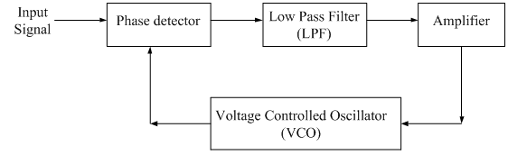
What are Phase-Locked Loops (PLL)? Definition, Block Diagram ... Block Diagram and Working of Phase-Locked Loop The figure here represents the basic block diagram of a phase-locked loop circuit: Let us now move further and understand how each block inside a PLL circuit operates in order to eliminate the phase error between two signals. Phase Detector A phase detector is nothing but a comparator here.
Phase Locked Loops
SAM D21/DA1 Family - Microchip Technology – Internal and external clock options with 48 MHz Digital Frequency-Locked Loop (DFLL48M) and 48 MHz to 96 MHz Fractional Digital Phase-Locked Loop (FDPLL96M) – External Interrupt Controller (EIC) – 16 external interrupts ... Block Diagram ...
Phase Locked Loop IC
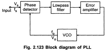
Phase Locked Loops, block diagram,working,operation,Design ... Block Diagram – Phase Locked Loops The input signal Vi with an input frequency fi is passed through a phase detector. A phase detector basically a comparator which compares the input frequency fiwith the feedback frequency fo .The phase detector provides an output error voltage Ver (=fi+fo),which is a DC voltage.
Phase Locked Loop: A fundamental building block in wireless ...
Phase-Locked Loop (PLL) Fundamentals - Analog Devices For phase-locked loop circuits, the bandwidth of the low-pass filter has a direct influence on the settling time of the system. The low-pass filter is the final element in our circuit. If settling time is critical, the loop bandwidth should be increased to the maximum bandwidth permissible for achieving stable lock and meeting phase noise and ...

Phase Locked Loop System Working and Applications
CD4046B Phase-Locked Loop: A Versatile Building Block for ... 4 CD4046B Phase-Locked Loop: A Versatile Building Block for Micropower Digital and Analog Applications 3 CD4046B PLL Technical Description Figure 2 shows a block diagram of the CD4046B, which has been implemented on a single monolithic integrated circuit. The PLL structure consists of a low-power, linear VCO and two
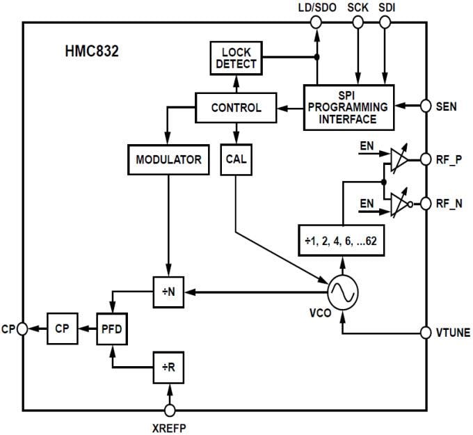
HMC832 Fractional-N Phase-Locked Loop (PLL) - ADI | Mouser
Phase-locked loop block diagram. | Download Scientific Diagram Phase Locked Loop (PLL) is basic building block of several communication systems to achieve synchronization. In this paper the PLL is designed using improved performance ring VCO with 0.18 μm ...

Driving the VCO of a High Voltage Phase-Locked Loop Frequency ...
Phased locked loop.docx - Phase-locked loop Simplest ... Phase-locked loop Simplest analog phase locked loop A phase-locked loop or phase lock loop abbreviated as PLL is a control system that generates an output signal whose phase is related to the phase of an input signal. There are several different types; the simplest is an electronic circuit consisting of a variable frequency oscillator and a phase detector in a feedback loop.

Simulation block diagram for a classical digital phase locked ...
Negative feedback - Wikipedia Negative feedback was implemented in the 17th Century. Cornelius Drebbel had built thermostatically-controlled incubators and ovens in the early 1600s, and centrifugal governors were used to regulate the distance and pressure between millstones in windmills. James Watt patented a form of governor in 1788 to control the speed of his steam engine, and James Clerk …

Demystifying phase-locked loops - Embedded.com
Writing a Phase-locked Loop in Straight C - liquidsdr.org scale:0.85 Continuous time analog phase-locked loop block diagram [ analog_pll_diagram ] depicts a simplified continuous-time analog PLL. We can think of the input to the system as being an unknown phase \(\phi\) , possibly corrupted by noise, while the output of is an estimate of this phase, \(\hat{\phi}\) .

Phase-Locked Loop (PLL) Fundamentals | Analog Devices
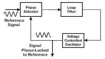
PLL Phase Locked Loop: How it Works - Electronics Notes The diagram for a basic phase locked loop shows the three main element of the PLL: phase detector, voltage controlled oscillator and the loop filter. In the basic PLL, reference signal and the signal from the voltage controlled oscillator are connected to the two input ports of the phase detector.

Phase Locked Loop System Working and Applications
PDF Phase Locked Loop Circuits - UC Santa Barbara Range of input signal frequencies over which the loop remains locked once it has captured the input signal. This can be limited either by the phase detector or the VCO frequency range. a. If limited by phase detector: π/2 π φ KDπ/2-KDπ/2 Ve 0 < φ < π is the active range where lock can be maintained. For the phase detector type

Phase-locked loop - Wikipedia
PLL FM Demodulator: Phase Locked Loop Detector ... The phase locked loop, PLL is a very useful RF building block. The PLL uses the concept of minimising the difference in phase between two signals: a reference signal and a local oscillator to replicate the reference signal frequency.
Phase-locked loop - Wikipedia
PLL Working | Phase Locked Loop Working operation The figure-1 depicts Block Diagram of Phase locked loop i.e. PLL Circuit in order to explain PLL working operation. PLL mathematical equation can be expressed as Fo = Fr * N , Hence Fo can be changed to different values within the range in either of the following ways. 1. keeping Fr fixed and varying N 2. Keeping N fixed and varying Fr.

Choose your PLL lock-time measurement - EDN
Describe the basic block diagram of the phase locked loop ... Phased Locked Loop (PLL) A phase locked loop is basically a closed loop system designed to lock the output frequency and phase to the frequency and phase of an input signal. They are used in applications such as frequency synthesis, frequency modulation/demodulation, AM detection, tracking filters, FSK demodulator, tone detector etc.
Optical Phase Locking techniques: an overview and a novel ...
Phase Locked Loop (PLL) - its Operation, Characteristics ... Block Diagram A PLL operates like a typical feedback system. It updates the output frequency of VCO until it matches the frequency of the input signal i.e. in sync with the input signal. Concept Of Operation The operation of Phase locked loop is based on the phase difference between the input and output signals.

PLL Phase Locked Loop: How it Works » Electronics Notes
Phase Locked Loop Operating Principle and Applications BASIC DIAGRAM OF PHASE LOCKED LOOP Block Diagram And Working Principle Of PLL The phase-locked loop consists of a phase detector, a voltage controlled oscillator and, in between them, a low pass filter is fixed. The input signal 'Vi' with an input frequency 'Fi' is conceded by a phase detector.

Consider the Source Part 1: What is a Phase Locked Loop ...
Phase Locked Loop System Working and Applications The figure shows the block diagram of the phase locked loop system in FM transmitter that consists of different blocks such as a crystal oscillator, phase detector, loop filter, voltage controlled oscillator (VCO), and frequency divider. Crystal Oscillator It is the most important part of the phase locked loop system.
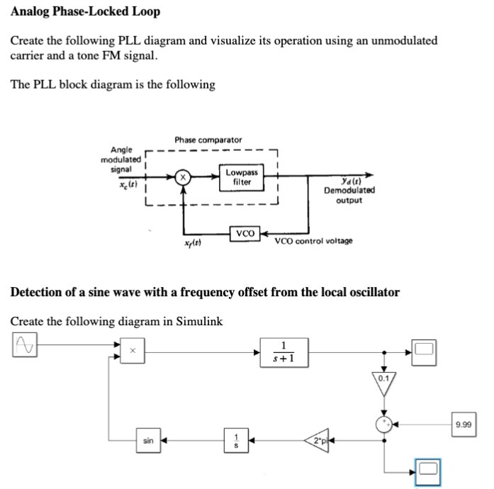
Solved Analog Phase-Locked Loop Create the following PLL ...
Phase Locked Loop | Analog-integrated-circuits || Electronics ...
Lab_6,7,8) Phase Lock Loop - D.Son978
Phase-Locked-Loop | Mini Projects | Electronics tutorial ...

Phase Locked Loop Tutorial - Block Diagrams - Electronics ...

Simulating phase locked loops with MATLAB
Sensors | Free Full-Text | Design and Implementation of an ...

Final Project: Phase Lock Loop Design - Shane McNamara Elec
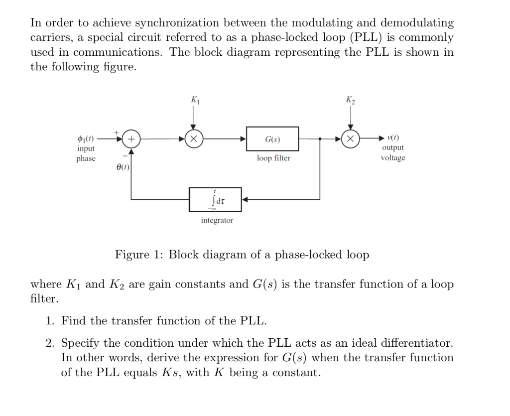
Solved In order to achieve synchronization between the ...
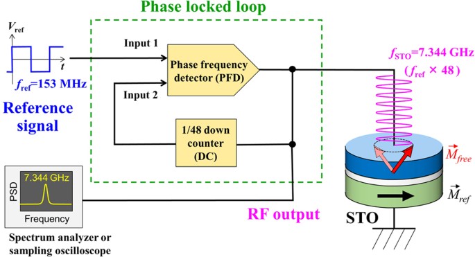
Extremely Coherent Microwave Emission from Spin Torque ...

Phase-Lock Loop Applications Using the MAX9382
Clock Generation Using PLL Frequency Synthesizers | DigiKey

Phase Locked Loop (PLL) and Delay Locked Loop (DLL) Basics ...

Phase Locked Loops - an overview | ScienceDirect Topics

Phase Locked Loop – Analog/RF IntgCkts

Phase-Locked Loops Worksheet - Analog Integrated Circuits
Phase Locked Loop Working Principle | PLL block diagram ...
0 Response to "38 phase locked loop block diagram"
Post a Comment