39 allen-bradley 700 relay wiring diagram
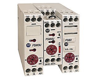
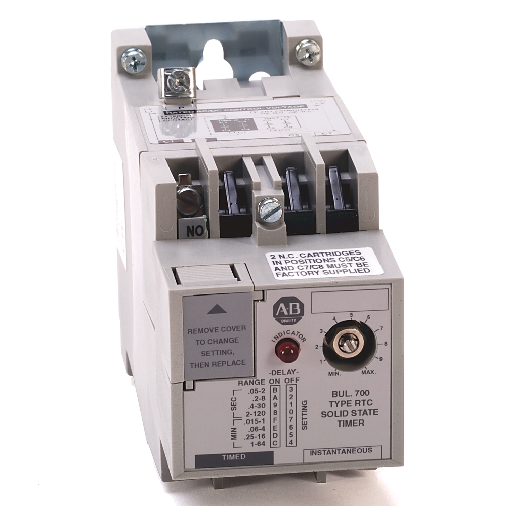
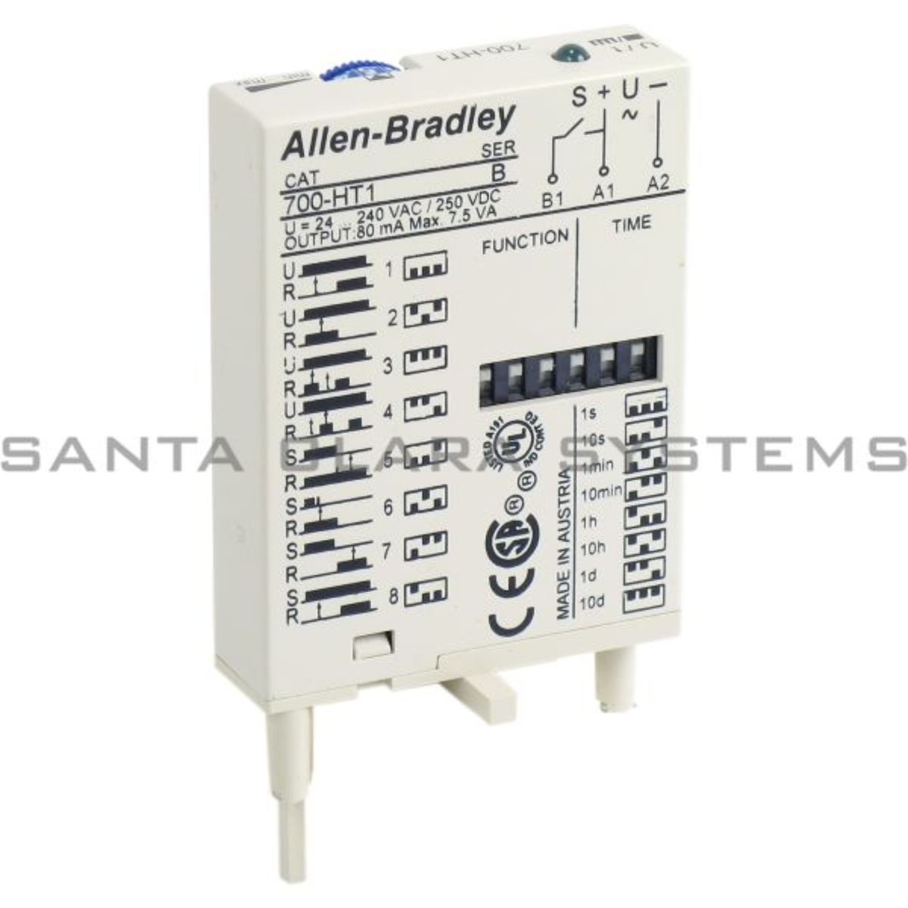
Allen Bradley 700 Relay Wiring Diagram - GORGEOUS DIAGRAM 700 N Low Profile Relays Allen Bradley United States. Wiring Diagrams ww introduction This booklet has been prepared as a guide to some of the useful ways Allen-Bradleys manual and magnetic across-the-line starters may be applied. 44 Beautiful 24vdc Relay Wiring Diagram Relay Electronic Parts Electromagnet Relays & Timers | Allen-Bradley United States NEMA Solid-state Timing Relays. Our Bulletin 700-PS Solid-state Timing Relays are accurate solid-state timers that can be mounted on 4-pole Bulletin 700-P, -PK, -R, or -RM relays and on 2-pole Bulletin 700-PH relays. Using an adapter plate, you can also mount it for standalone use. Product Details.
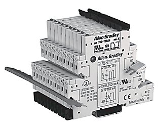
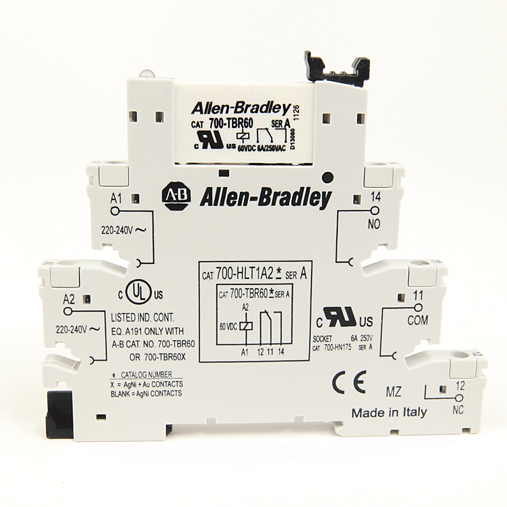
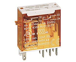
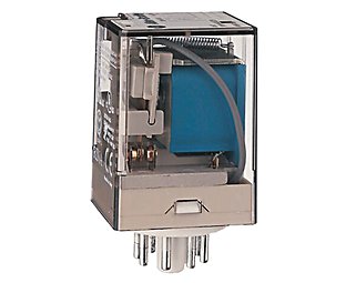
700-N Low Profile Industrial Relays | Allen-Bradley United ... Our Bulletin 700-N Industrial Relays are a low profile, high reliability switching solution. These electrically held relays have manual override capability with easy-to-identify status indication on the highly visible red bar. Contact a Distributor Find A Sales Office. Support. Support.
Allen-bradley 700 relay wiring diagram
PDF Literature Library | Rockwell Automation Literature Library | Rockwell Automation PDF Bulletin 700P NEMA AC Integral DIN Relay - Rockwell Automation that allows the Allen-Bradley Bulletin 700 heavy duty AC NEMA relays (up to 12 poles) to be installed on 35 mm DIN Rail. This new feature ... • Contact terminal screws are easily accessed for wiring and continuity testing ... Bulletin 700-P Relays- ... PDF Allen-Bradley 700-FSK3CU23-EX - Harvard University ‡ Available on multifunction "M," and single function "A" or "B" option timing relays along with code "4" (2PDT contacts). Bridge or potentiometer 10 kΩ, 0.25 W min. (low voltage) for external time setting.
Allen-bradley 700 relay wiring diagram. PDF Bulletin 700-P Heavy-Duty Industrial Relays Allen-Bradley distributor. Electrically Held Relays — Typical Wiring Diagrams Contacts Contact Arrangement and Markings Open Type Relay Rail Mount Open Type DIN Rail Mount N.O. N.O. Cat. No. Cat. No. 2 — 4-Pole Relay 700DC-PK200 ⊗700DC-PK200D 4— 700DC-PK400⊗ 700DC-PK400D⊗ 6 — 8-Pole Relay 700DC-PK600 ⊗700DC-PK600D PDF Bulletin 700S-CF IEC Industrial Control Relays Allen-Bradley 700S-CF620EJBC. Bulletin 700S-CF ... connection such as a loose wire). ... Helps prevent restart of the 5 safety outputs if there is a single fault anywhere in the system. Use (3) 700S-CF relays and this diagram to construct the circuit Basic Circuit (1) Output Circuit (3 Relays, 9 Terminal Blocks) ... Miniature "Ice Cube" Relays | Allen-Bradley United States Our Bulletin 700-HC Miniature Square Base Relays are 4-pole plug-in relays for your low-energy switching applications. Contact a Distributor Find A Sales Office Support. Get Support Distributor. Find a Product Partner Popular Resources/Quicklinks ... FactoryTalk and Allen‑Bradley products, services and solutions. ... 🇹🇹 ⚡⏲ ALLEN-BRADLEY 11 PIN (700 ... - YouTube #allenbradley #relay #powerThis timer is wonderful and easy to use with all it's different FUNCTIONS WHO CAN GO WRONG.
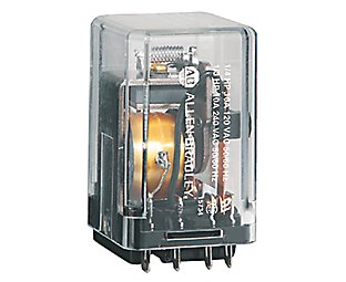
PDF BULLETIN 700-HA TUBE BASE RELAY - Tasker Bulletin 700-HA Tube Base Relay with PIN Terminals (Single Contact) — Mechanical ON/OFF Indicator included BULLETIN 700-HA TUBE BASE RELAY Product Overview Build a Catalog Number Description Contact Rating Wiring Diagrams Coil Voltage Cat. No.7 ‡ § U.S./Canada International DPDT 2-pole 2 Form C Single AgNi Contact 10 A B300 PDF General Purpose, Interposing, Solid-State and Specialty Relays 700-HA700-HA 700-HB700-HB 700-HD700-HD Allen-Bradley relays and timers off er compatible and versatile solutions for control applications - from programmable controllers and motor starters to push buttons and terminal blocks. General purpose relays feature an excellent fl exible design and industry-proven reliability. Download Allen Bradley 700 Relay Wiring Diagram Pictures ... Home » wiring diagram » allen bradley safety relay wiring diagram. 2004 polaris sportsman 600 twin wiring diagram. Allen bradley 700 series relay contact conversion. First choose the wire then the reel number where you want it spooled. 2004 polaris sportsman 600 twin wiring diagram. Source: General purpose relays timing relays u0026 timers ... PDF 700-2.14: Safety Relays - Rockwell Automation This is similar to the internal circuit found in an Allen -Bradley safety relay. It is redundant because it uses three relays (redundancy requires two ... Wiring Diagram and logic circuit for 700-ZBR520-- And 700-ZBR100--Figure 5 Safety Relay Operating Principle. 50 msec Max Legend 0 1 8 Safety Relays E-Stop Open All relays are
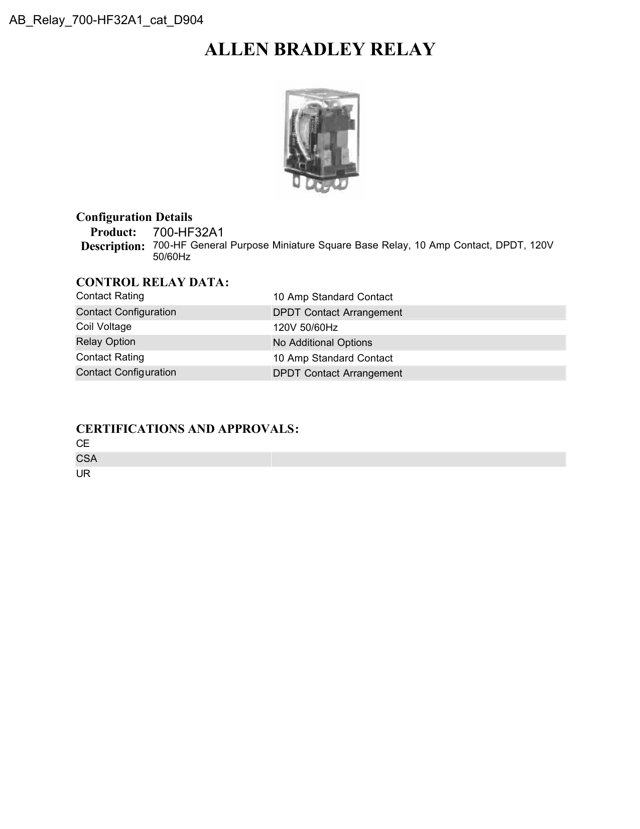
PDF Bulletin 700-FE - Rockwell Automation Allen-Bradley Part Numbers 700-FEA1SU22 700-FEB1SU22 700-FED1SU22 700-FEF1SU22 700-FEM1RU22 700-FEA1TU22 serA 700-FEB1TU22 serA 700-FED1TU22 serA 700-FEF1TU22 serA 700-FEM1TU22 serA Terminal Layout 700-FEM1R / 700-FEB1S A1 A3 15 18 A2 B1 A1 B1 15 Empty 18 A2 Terminal Layout 700-FE_1S A1 A3 15 18 A2 Empty A1 Empty 15 Empty 18 A2 Allen Bradley Safety Relay Wiring Diagram - Wirings Diagram Allen Bradley Safety Relay Wiring Diagram - allen bradley guardmaster safety relay wiring diagram, allen bradley safety relay wiring diagram, Every electric structure consists of various distinct pieces. Each component ought to be placed and connected with other parts in particular way. If not, the structure will not work as it should be. PDF Bulletin 700-HF - Rockwell Automation ∂ Push-to-Test and Manual Override Option: Add suffix (-3) to the selected bulletin 700-HF relay. Description Wiring Diagrams Coil Voltage Cat. No. U.S./Canada International ⋆ ‡ ∂ DPDT 2-pole 2 Form C AgCdO Contacts 6V AC 700-HF32A06 12V AC 700-HF32A12 24V AC 700-HF32A24 120V AC 700-HF32A1 240V AC 700-HF32A2 6V DC 700-HF32Z06 12V DC 700 ... Allen Bradley 700 Relay Wiring Diagram - Wiring Diagram Allen Bradley 700 Relay Wiring Diagram. Relay and timer specifications technical data 700 hls2z24 allen bradley 有現貨 santa clara systems asi equivalent hlt1z24 terminal block hlt2z24 24v dc gp india ha33z2 3 4 ha general purpose base 10 amp contact 3pdt 220v push to test manual override function pilot light quad industry gmbh hn154 11 ...
PDF GI-2.0: Typical Wiring Diagrams - Rockwell Automation Wiring Diagrams ww introduction This booklet has been prepared as a guide to some of the useful ways Allen-Bradley's manual and magnetic across-the-line starters may be applied. It will also serve as a useful aid where simple wiring systems are to be studied. When applying these diagrams, it is well to
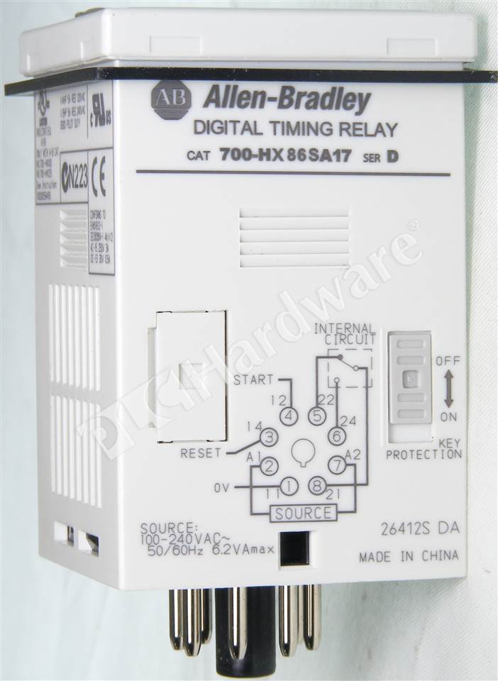
PDF Bulletin 700-HR Plug-in Timing Relays - Harvard University Pin for use with Bulletin 700-HR and -HX timing relays. No retainer clip required. 10 700-HN125 Cat. No. 700-HN125 Screw Terminal Tube Base Sockets — Panel or DIN Rail Mounting; Guarded Terminal Construction. 11-pin for use with 3PDT 700-HA relays. 10 700-HN101 Cat. No. 700-HN101
PDF Allen-Bradley 700-FSK3CU23-EX - Harvard University ‡ Available on multifunction "M," and single function "A" or "B" option timing relays along with code "4" (2PDT contacts). Bridge or potentiometer 10 kΩ, 0.25 W min. (low voltage) for external time setting.
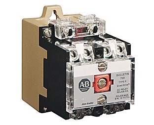
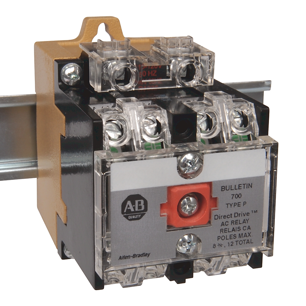
PDF Bulletin 700P NEMA AC Integral DIN Relay - Rockwell Automation that allows the Allen-Bradley Bulletin 700 heavy duty AC NEMA relays (up to 12 poles) to be installed on 35 mm DIN Rail. This new feature ... • Contact terminal screws are easily accessed for wiring and continuity testing ... Bulletin 700-P Relays- ...
PDF Literature Library | Rockwell Automation Literature Library | Rockwell Automation












0 Response to "39 allen-bradley 700 relay wiring diagram"
Post a Comment