39 lng process flow diagram
LNG Liquefaction Plants - Chart Industries Chart's modular liquefaction plants and associated process technology enable displacement of liquid fuels through small- and mid-scale LNG. Defining the New Generation of Liquefaction Plants Chart defined small-scale LNG through a range of standard plants with capacities ranging from 3,000 gallons per day (10 tons per day) to 450,000 gallons ... Natural Gas Liquefaction Simplified LNG plant block diagram TEP 10 – Gas Processing and LNG – Fall 2008. Jostein Pettersen ... Hammerfest LNG plant - block flow diagram ... Gas liquefaction process - ideal.28 pages
Lng Process Flow Diagram - Diagram Niche Ideas Lng process flow diagram. The process flow diagram (pfd) represents a quantum step up from the bfd in terms of the amount of information that it contains. Overview lng terminal flow diagram process description recondenser design detailed description of the figure control systems to bog recondensation process.

Lng process flow diagram
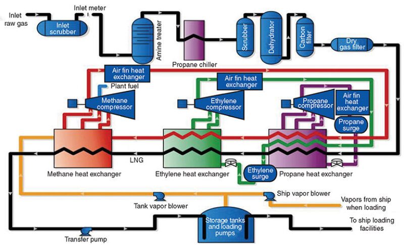
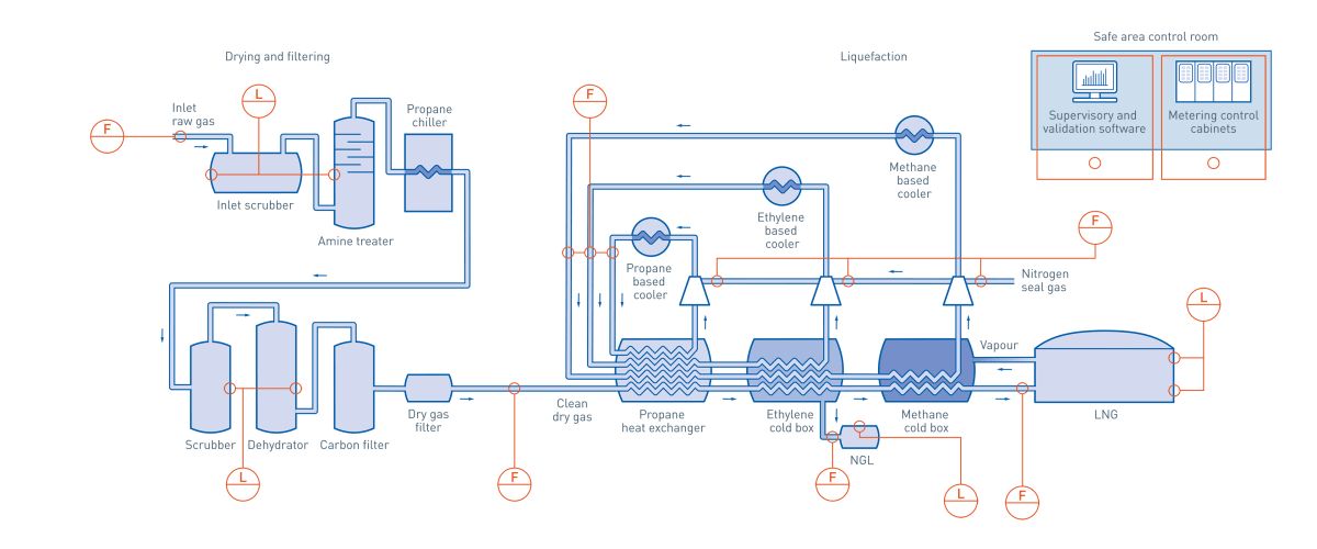
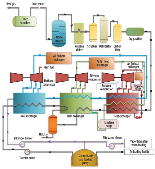
Process selection and recent design innovations for LNG ... Optimized cascade process. The optimized cascade process (OCP) is a simple and reliable technology. A process flow diagram for the OCP is shown in Fig. 6. In this process, three pure-component refrigerants (namely propane, ethane and methane) are used at different pressures during the refrigeration and liquefaction processes. files.chartindustries.com › BAHX-LNG-processexplore how gas liquefaction. - Chart Industries improves process efficiency. Another advantage of using BAHXs in MR processes is the ability to scale capacity. BAHXs work well in both small and multi-train mid scale LNG applications as capacity can be easily managed for increasingly larger flow volumes. The construction of Figure 6. IPSMR® mixed refrigerant process technology scheme. Liquefied Natural Gas (LNG) - WordPress.com The refrigeration and liquefaction process is the key ele- ment of an LNG project, ... An example of a LNG plant overall flow diagram and the main pro-.33 pages
Lng process flow diagram. PDF LNG Dehydration(Drying of Natural Gas) - CHERIC LNG Dehydration(Drying of Natural Gas) Absorption and refrigeration with hydrate inhibition is the most common dehydration process used to meet pipeline sales specifications. ... Insensitive to moderate changes in gas temperature, flow rate, and pressure. They are relatively free from problems of corrosion, foaming, etc. Liquefied Natural Gas Process - an overview ... The following is a general guideline for the startup for an LNG production plant. A generic C3MCR liquefaction train process flow diagram is shown in Figure 7-2.Startup of other liquefaction technologies may be slightly different. Liquified Natural Gas: Properties, Uses, Origin ... Liquefied Natural Gas or LNG is natural gas with the primary element as methane. The Liquefied Natural Gas is converted to liquid form for ease of transport and storage. While in liquid form, Liquified Natural Gas takes up around 1/600th of the volume of its gaseous form. So, LNG can easily be transported in liquid form in locations where natural gas transportation through pipelines is not ... PDF Energy Systems - Chart Industries processing and Chart's process expertise and proven experience in providing integrated NRU systems that enrich and recover helium is highly regarded by companies around the world seeking to exploit their valuable helium resources. Liquefied Natural Gas Chart is developing the LNG infra-structure right across
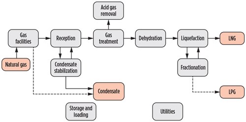
PDF LNG Plants - Technical operations (Part I) LNG plant normal operation . Molecular sieve unit: Designed to meet the product specifications on water and mercaptans (RSH) content. The main items that should be checked in this unit: • Mercaptans buildup • Regeneration gas temperature • Flow rate • Flow channeling • Oxygen • Inlet separator • Bed fouling • Dehydratation bed ... Liquefied Natural Gas (LNG): Exploration & Production ... LNG Process Flow Diagram Natural-gas Condensate (Condensate), a by-product of the LNG process is a low-density mixture of hydrocarbon liquids that are present as gaseous components in the raw natural gas produced from many natural gas fields. PDF Liquefied Natural Gas and Floating LNG - AIChE Liquefied Natural Gas and Liquefied Hazardous Gas • 49-CFR-193 LNG Facilities: Federal Safety Standards • NFPA 59A Standard for the Production, (2001) Storage and Handling of LNG LNG Process Safety LNG Gabriel Castaneda, P.E. 49-CFR-193 is based on NFPA 59A, 2001 Natural Gas Industry Process Flow Diagram - SmartDraw Natural Gas Industry Process Flow Diagram. Create Process Flow Diagram examples like this template called Natural Gas Industry Process Flow Diagram that you can easily edit and customize in minutes. 1/16 EXAMPLES.
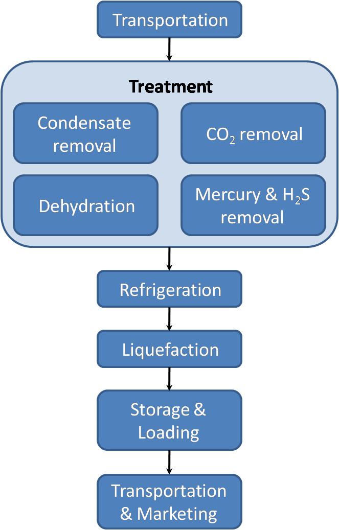
PDF 6. Project Description: Lng Plant A simplified schematic of the LNG process is shown in Figure 6.4. Although similar, the liquefaction process varies depending on the powering option adopted for the LNG plant - all mechanical drive or all electrical power. Figures 6.5 and 6.6 show simplified process flow diagrams for the plant for the mechanical drive and electrical power options PDF Processes and Pump Services in The Lng Industry Liquefaction Process A block flow diagram of the liquefaction process is shown in Figure 2. The first step in the process is removal of acid gases such as carbon dioxide (CO2) and hydrogen sulfide (H2S). CO2 would freeze at cryogenic process temperatures and H 2S must be removed to meet the LNG product specifications. Typical specifications for › class › che-designDesign of LNG Facilities - University of Oklahoma Flow Diagram for a Typical LNG Plant LNG (Liquefied Natural Gas) Basics Combustible mixture of hydrocarbons Dry VS. Wet NGL Extraction Dehydration/Scrubbing Liquefied Natural Gas Target temperature for Natural gas:-260°F Reduces volume by a factor 600 Objective Main Objectives Simulate Processes Optimize Processes Minimize compressor work PDF LNG Plant Overview - Murmanshelf •At atmospheric pressure LNG has a temperature of about -162ºC •LNG contains about 85-95 % methane •LNG is colorless, odorless, non-corrosive and non-toxic •Evaporated LNG can displace oxygen and cause human suffocation •Flammability range, 5-15 vol % concentration in air •Autoignition temperature, 540 C 5 LNG is a cryogenic liquid
Natural Gas Liquefaction Processes: Design and Optimisation ...
cameronlng.com › 2018 › 10and the Liquefaction Process - Cameron LNG storage tanks, which takes approximately 14-16 hours. The LNG remains at -160°C for the duration of the process. LNG has been transported commercially by ships since 1964 and as of the end of 2016 there have been 88,000 cargoes or 176,000 voyages without an LNG loss. T. ransPorTaTion. A 155,000 m. 3. membrane vessel is approximately the same ...

A generalized natural gas industry process flow diagram that ...
› watchLNG Plant Flow Chart - YouTube Liquefied Natural Gas (LNG) is Natural Gas that has been cooled to –260° F (–162° C), changing it from a gas into a liquid that is 1/600th of its original vo...
Liquefied Natural Gas (LNG)
› media › filesLiquefied Natural Gas (LNG) - SPE-GCS –Onshore LNG vs. FLNG, baseload plants vs. tolling facilities •Market views / growth of LNG –Industry statistics, project forecasts, and LNG news •Review of liquefaction projects and process technologies –History, size, and growth of LNG trains and complexes –Licensor share, process selection, cycle efficiency, equipment, etc.

Typical Process Diagram of Small LNG Refasification
Flow diagram of LNG process | Download Scientific Diagram The LCI was initiated with the drawing of a flow diagram specifically for Western Australian LNG production in Darwin and Karratha (Figure 1) in which the boundaries for each of the above mentioned...

Gas Gorgon gas project Liquefied natural gas Regasification ...
Regasification Facility - an overview | ScienceDirect Topics An example of a LNG plant overall flow diagram and the main process units are shown in Figure 6-1. Typically, the feed gas is delivered at high pressure (for example, up to 1,300 psi) from upstream gas fields via trunklines and any associated condensate will be removed.
LNG Plant Overview
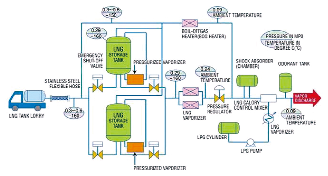
missrifka.com › energy › lngTypical Process Diagram of Small LNG Refasification Dec 18, 2018 · Typical Process Diagram for Small LNG Regasification (Part 1) August 2, 2016 December 18, 2018 Rifka Aisyah LNG. Today I want to share you Typical Process Diagram for Small LNG Regasification. For your information, small LNG regasification is very useful to be built in remote location where power supply is very limited.

Gas Processing Plant Process Flow Diagram and Explanation
LNG - SlideShare Fig. 2 Cascade Process Simplified Flow Diagram 3.1.1. LINDE PROCESS This process is a three cycle process, like the cascade process, but with mixed refrigerant on all cycles (Fig.3.). Compared to the cascade, the efficiency is better, as mixed refrigerants allows to have 9. 9 a closer approach.
Basic Properties of LNG
Typical Process Diagram for Small LNG Regasification (Part 2) Typical Process Diagram for Small LNG Regasification (Part 2) August 2, 2016 December 18, 2018 Rifka Aisyah LNG As mentioned in part 1, small LNG regasification facility typically consists of LNG unloading facility (which can be flexible hose or marine loading arm), LNG storage tank, LNG sendout pump, ambient air vaporizer, and metering .

Liquified Natural Gas: Properties, Uses, Origin, Composition ...
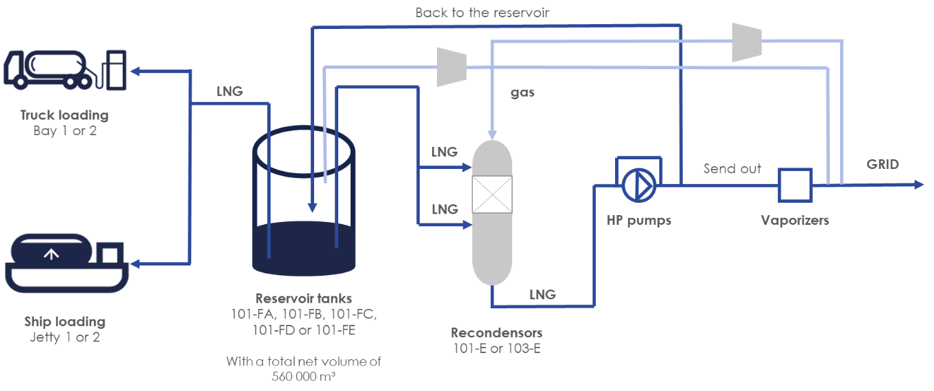
PDF MWKL LNG Terminals Recent Developments II. The Process A simplified process flow diagram is shown in Figure 1. Figure 1 - LNG Receiving Terminal Simplified Process Flow Diagram The LNG receiving terminal receives liquefied natural gas from special ships, stores the liquid in special storage tanks, vaporises the LNG, and then delivers the natural gas into a distribution pipeline.
Process flow of a typical LNG receiving and regasification ...
› figure › Process-flow-of-a-typical-LNG-receiving-and-reProcess flow of a typical LNG receiving and regasification ... Download scientific diagram | Process flow of a typical LNG receiving and regasification terminal. from publication: Comparative Well-to-Tank energy use and greenhouse gas assessment of natural ...
Will LNG Plants Meet a Growing Demand for Clean Energy?
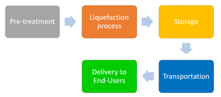
PDF LNG R&D for the Liquefaction and Regasification Processes Basically the LNG process is composed by the following steps[1]: Extracted natural gas is liquefied in the production field or in a close site, after removing the impurities. Usually, in the liquefaction process the gas is cooled to a temperature of approximately -162°C at ambient pressure. Then, the LNG is loaded onto double-hulled ships which
KOREA GAS ENGINEERING - Endeavor and Passion make the possible.
PDF LNG Technology - Linde Engineering Liquefied Natural Gas LNG is natural gas in liquid form. In order to liquefy natural gas, it must be cooled to cryogenic temperatures of approximately -160°C. As a liquid, natural gas occupies only 1/600 of the volume of natural gas (at atmospheric pressure) in gaseous form, making LNG more economical and practical to store.
Liquefied Natural Gas in the oil & gas industry | KROHNE ...
Liquefied Natural Gas (LNG) - WordPress.com The refrigeration and liquefaction process is the key ele- ment of an LNG project, ... An example of a LNG plant overall flow diagram and the main pro-.33 pages

How Does an LNG Plant Work?
files.chartindustries.com › BAHX-LNG-processexplore how gas liquefaction. - Chart Industries improves process efficiency. Another advantage of using BAHXs in MR processes is the ability to scale capacity. BAHXs work well in both small and multi-train mid scale LNG applications as capacity can be easily managed for increasingly larger flow volumes. The construction of Figure 6. IPSMR® mixed refrigerant process technology scheme.

Flowchart for LNG plant with two trains | Download Scientific ...
Process selection and recent design innovations for LNG ... Optimized cascade process. The optimized cascade process (OCP) is a simple and reliable technology. A process flow diagram for the OCP is shown in Fig. 6. In this process, three pure-component refrigerants (namely propane, ethane and methane) are used at different pressures during the refrigeration and liquefaction processes.
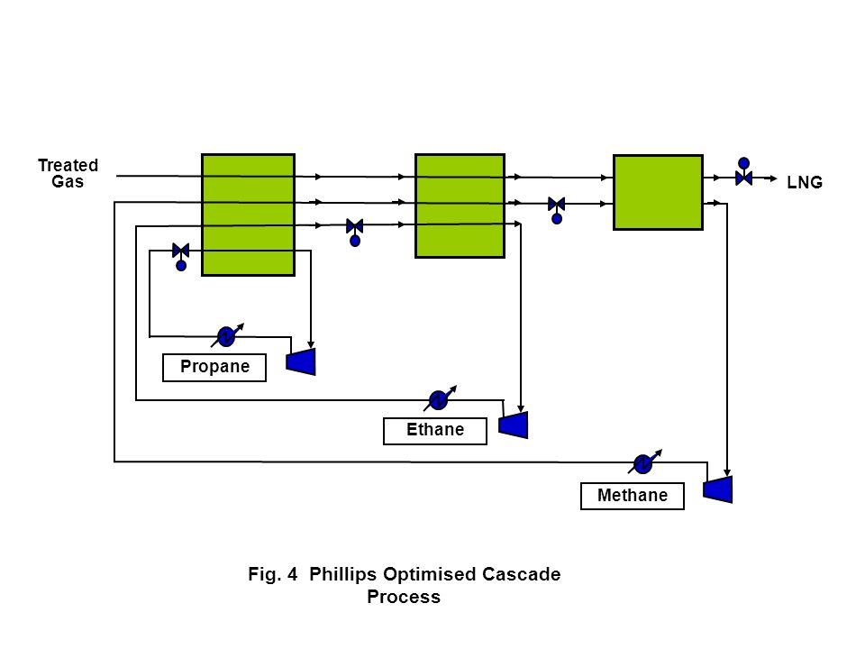
Fig. 1 LNG Block Flow Diagram - ppt video online download

Simplified process flow diagram for the operating LNG train ...
Process Modeling of an Innovative Power to LNG Demonstration ...
BioLNG te Zeebrugge

LNG industry faces challenge of monetizing huge CSG resources ...

Overview of LNG Technologies | OwnerTeamConsultation
Liquefied natural gas - Wikipedia

Liquefied Natural Gas Process - an overview | ScienceDirect ...
Process selection and recent design innovations for LNG ...
Process Modeling of an Innovative Power to LNG Demonstration ...
Contamination Control for LNG Production

How LNG Terminals Work

Floating LNG Plant Processess and Equipment
Process selection and recent design innovations for LNG ...
LNG R&D for the Liquefaction and Regasification Processes

Liquified Natural Gas: Properties, Uses, Origin, Composition ...

Optimized Cascade Process | ConocoPhillips LNG Technology ...
YAMAL LNG: MEETING THE CHALLENGES OF NATURAL GAS LIQUEFACTION ...
Optimization control of LNG regasification plant using Model ...

Natural Gas Liquefaction - ScienceDirect
World Bank Document
Liquefied natural gas - Wikipedia

16 Chemical manufacturing process flow chart ideas | process ...
Natural Gas Liquefaction Simplified LNG plant block diagram
0 Response to "39 lng process flow diagram"
Post a Comment