39 udp state transition diagram
OS Process State and State Transition Diagram... - EXAMRADAR What is process state? Explain state transition diagram. Transition 4 occurs when the external event for which a process was waiting (such as the arrival of some input) happens. If no other process is running at that time, transition 3 will be triggered and the process will start running. UML protocol state machine diagrams overview, show usage... Major elements of the protocol state machine diagram are protocol state, protocol transition, and different pseudostates, as shown on the overview diagram below.
PDF TCP/IP Illustrated | Chapter 11. UDP: User Datagram Protocol 10.4 RIP: Routing Information Protocol 10.5 RIP Version 2 10.6 OSPF: Open Shortest Path First 10.7 BGP: Border Gateway Protocol 10.8 CIDR: Classless Interdomain Routing 10.9 Summary. Chapter 11. UDP: User Datagram Protocol.

Udp state transition diagram
What is State Transition Testing? Diagram, Technique, Example In state transition diagram the states are shown in boxed texts, and the transition is represented by arrows. It is also called State Chart or Graph. State Transition testing is defined as the testing technique in which changes in input conditions cause's state changes in the Application under Test. TCP connection status | Table 1. TCP state transition description table ...diagram illustrates the possible states for a TCP connection and how the states transition based Waiting for a connection request from a remote TCP application. This is the state in which you can For UDP sockets, the foreign socket field that is shown in the various Netstat reports is displayed as... State Machine Diagram - UML 2 Tutorial | Sparx Systems A state machine diagram models the behaviour of a single object, specifying the sequence of events that an object goes through during its lifetime in A state can have a transition that returns to itself, as in the following diagram. This is most useful when an effect is associated with the transition.
Udp state transition diagram. State Transition Diagram - an overview | ScienceDirect Topics The state transition diagram is abstract in that it uses states labeled {S0, S1, S2, S3} and outputs labeled {red, yellow, green}. To build a real circuit, the states and outputs must be assigned binary encodings . Ben chooses the simple encodings given in Tables 3.2 and 3.3 . Tranquility: TCP State Transition Diagram One reason for showing the state transition diagram is to show the 11 TCP states with their names. These states are displayed by netstat, which is a useful tool when debugging client/server applications. State Transition Diagram with example in software... | T4Tutorials.com What is the State transition Diagram? When we write our program in Object-oriented programming, then we need to take classes and objects. In the state transition diagram, a guard is a boolean expression. Suppose if the guard is true, then it enables an event to trigger a transition. PDF Topic support guide | 2.1 What are state-transition diagrams? State-transition diagrams are also useful for showing the working of algorithms that involve a finite number of states. The following are useful resources for understanding state-transition diagrams. The content of websites is dynamic and constantly changing.
PDF Figure 4. 802.11 MAC state transition diagram State transition diagram can help us read or write network programs. Figure 4 shows a reference 802.11 state transition diagram [5]. The main states in ns-2 are described as follows. (b) Figure 8. UDP Throughputs and Captures/Collisions at a function of the distance d from BS (a) Without Fading... All You Need to Know about State Diagrams A state diagram consists of states, transitions, events, and activities. You use state diagrams to illustrate the dynamic view of a system. They are especially important in modeling the behavior of an interface, class, or collaboration. State Transition Diagrams State-Transition diagrams, like decision tables, are another excellent tool to capture certain types of system requirements and to document internal system design. These diagrams document the events that come into and are processed by a system as well as the system's responses. (PDF) State Transition Diagrams State transition diagrams are based on the concept of a state machine (STM), which we introduce first. ... ... Note that none of the above given sets needs to be finite. A finite representation is obtained by a graphical notation, called state transition diagrams (STDs) [14].
Figure 3-2 Process State Transition Diagram Process State Transition. Applications that have strict real-time constraints might need to prevent processes from being swapped or paged out to secondary memory. An active process is normally in one of the five states in the diagram. State Transition Testing Technique and State Transition Diagram... Learn what is State Transition Testing and How to use State Transition Diagram: In our last article, we saw the 'Cause and Effect graph' test case writing technique. Today let's move to the next dynamic test case writing method - State Transition technique. PDF Media Access Control Protocol Based on DOCSIS 1.1 The top-level state transition diagram filters Dynamic Service messages and passes them to the appropriate transaction based on Service Flow Identifier (SFID), Service Flow Reference number, and TransactionID. State Transition Diagram for an ATM System - GeeksforGeeks uccState Transition Diagram are also known as Dynamic models. As the name suggests, it is a type of diagram that is used The System consists of various states that are being represented using various symbols in the state transition diagram. You can see the symbols and their description given below
State transition diagram for the AR-TP protocol operation ...
State-Transition Diagrams | StickyMinds State-Transition Diagrams State-transition diagrams describe all of the states that an object can have, the events under which an object changes state (transitions), the conditions that must be fulfilled before the transition will occur (guards), and the activities undertaken during the life of an object...

State Transition Diagram of TCP Reno | Download Scientific ...
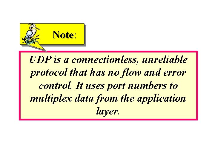
User Datagram Protocol - Wikipedia In computer networking, the User Datagram Protocol (UDP) is one of the core members of the Internet protocol suite. With UDP, computer applications can send messages...
Manual TwinCAT 3 | TCP/UDP Realtime
Modeling System States: State-Transition Diagrams and... | Medium State-transition diagrams and state tables are two analysis models that provide a concise, complete, and unambiguous representation of an object's or When our user representatives reviewed my first draft of this diagram, they identified one state that wasn't needed, noticed that another essential...
State
State Transition Diagram State transition diagrams describe the logical transition of a system through various states of operation. Presented in a freeform layout, the state transition diagram represents states, the transitions that connect them, and the events that trigger transitions.

Structure and Mechanism of Human UDP-xylose Synthase ...
uml - difference between state chart, state machine diagrams and... what are the differences between state chart diagrams, state machine diagrams and state transition diagrams? while at several places i got to learn UML state machine diagram also known as UML statechart diagram. It shows state transitions in the system. So in UML context, practically they all...

Communication Networks/TCP and UDP Protocols - Wikibooks ...
3SL Reference: State Transition Diagram (STD) - Functional Diagram State Transition Diagrams (STDs) are used along with specifications to define the functional detail for a system. Unlike data processes, control processes have a specialised role: enforcing sequencing over environmental control stimuli to the system, and the internal operation of the system.
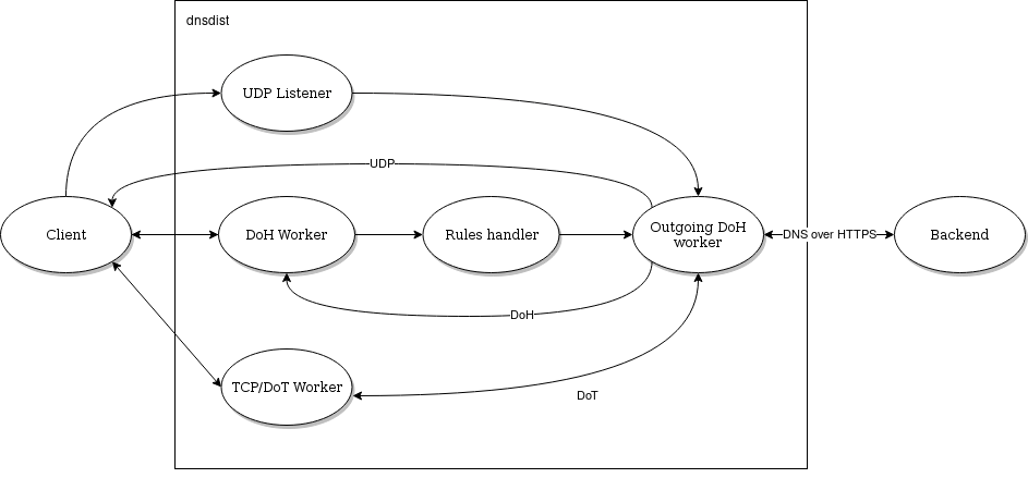
Performance Tuning — dnsdist documentation
State Transition Testing | TMap State Transition testing is a process-oriented test design technique that focuses on states, events that initiate a transition to another state and Since a state transition diagram doesn't show invalid transitions, only test cases with valid transitions can be derived from a state transition diagram.
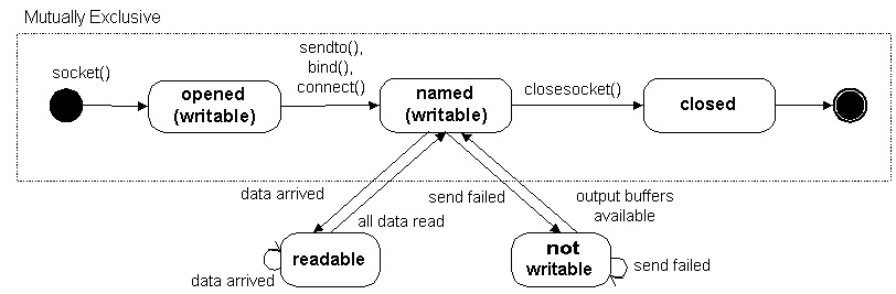
Socket States
State Machine Diagram - UML 2 Tutorial | Sparx Systems A state machine diagram models the behaviour of a single object, specifying the sequence of events that an object goes through during its lifetime in A state can have a transition that returns to itself, as in the following diagram. This is most useful when an effect is associated with the transition.

User Datagram Protocol (UDP) (article) | Khan Academy
TCP connection status | Table 1. TCP state transition description table ...diagram illustrates the possible states for a TCP connection and how the states transition based Waiting for a connection request from a remote TCP application. This is the state in which you can For UDP sockets, the foreign socket field that is shown in the various Netstat reports is displayed as...
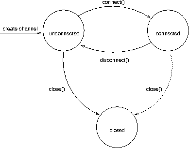
Chapter 3. API
What is State Transition Testing? Diagram, Technique, Example In state transition diagram the states are shown in boxed texts, and the transition is represented by arrows. It is also called State Chart or Graph. State Transition testing is defined as the testing technique in which changes in input conditions cause's state changes in the Application under Test.

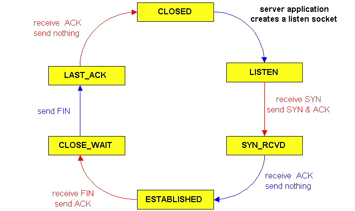
State Transition Diagram of server's application. | Download ...

Communication Networks/TCP and UDP Protocols - Wikibooks ...
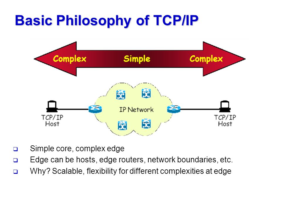
The Transport Layer: TCP and UDP Chap 2. Basic Philosophy of ...

16 UDP Transport — An Introduction to Computer Networks ...
OpenState: An Interface for Stateful Packet Processing in ...

Chapter 2. The Transport Layer: TCP, UDP, and SCTP ...

State transition diagram for ATCP at the sender [8 ...
Kapitel 22 UDP och TCP Kapitel 23 Congestion
Draw a state transition diagram | MCA IGNOU GROUP
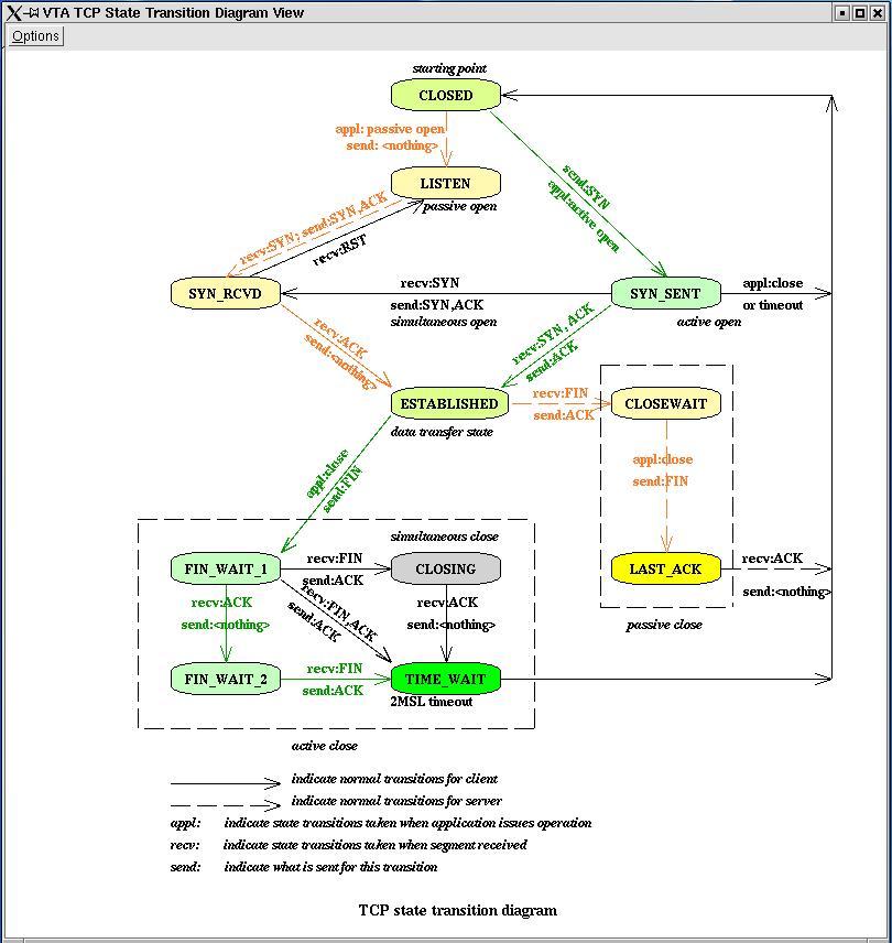
VTA User's Guide: V1.0 for VTA 1.0 Chapter 3. Using VTA 3.3 ...

Tcp State Transition Diagram - Digital Transmission
![MS-RDPEA]: Message Processing Events and Sequencing Rules ...](https://docs.microsoft.com/en-us/openspecs/windows_protocols/ms-rdpea/ms-rdpea_files/image007.png)
MS-RDPEA]: Message Processing Events and Sequencing Rules ...

State Transition Diagram of server's application. | Download ...

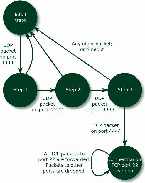
State transition diagram for HTH Upon arrival of a UDP packet ...
Solved] SCTP uses a transition state diagram to handle ...

State Transition Diagram of server's application. | Download ...
Protocol states and transition - Stack Overflow

State transition diagram for HTH Upon arrival of a UDP packet ...

Synthesis and Biochemical Properties of Reversible Inhibitors ...
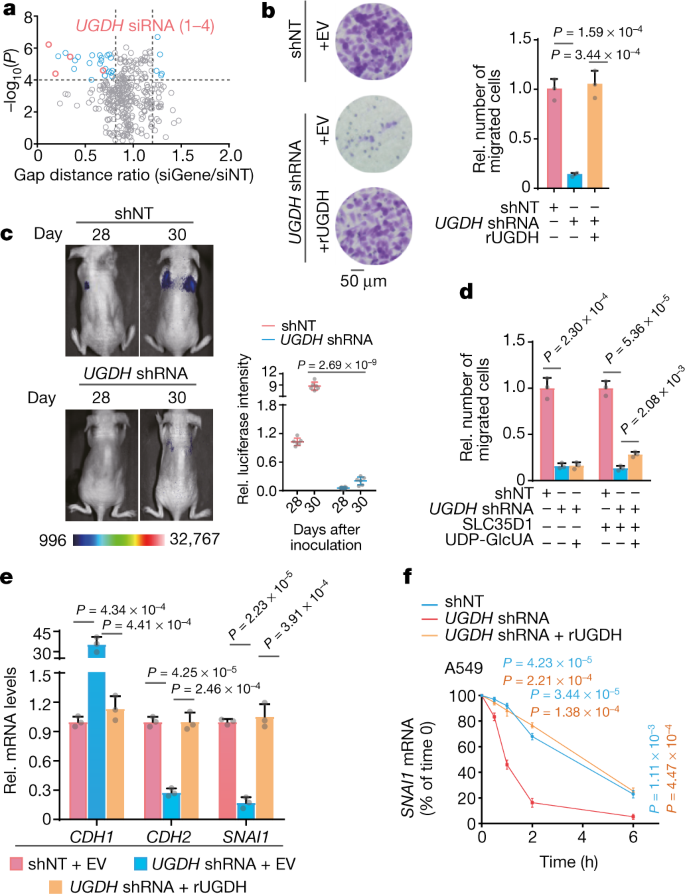
UDP-glucose accelerates SNAI1 mRNA decay and impairs lung ...
Transmission Control Protocol
State Transition Diagram

Transport Layer: TCP and UDP

State transition diagram for the TCP Reno. | Download ...
TCP/UDP and Sockets Study Notes for GATE & Computer Science ...
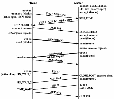
Chapter 18. TCP Connection Establishment and Termination
Synthesis and biological evaluation of new inhibitors of UDP ...

File:Tcp state diagram fixed new.svg - Wikimedia Commons
UDP Protocol | User Datagram Protocol - javatpoint
0 Response to "39 udp state transition diagram"
Post a Comment