38 hubbell occupancy sensor wiring diagram
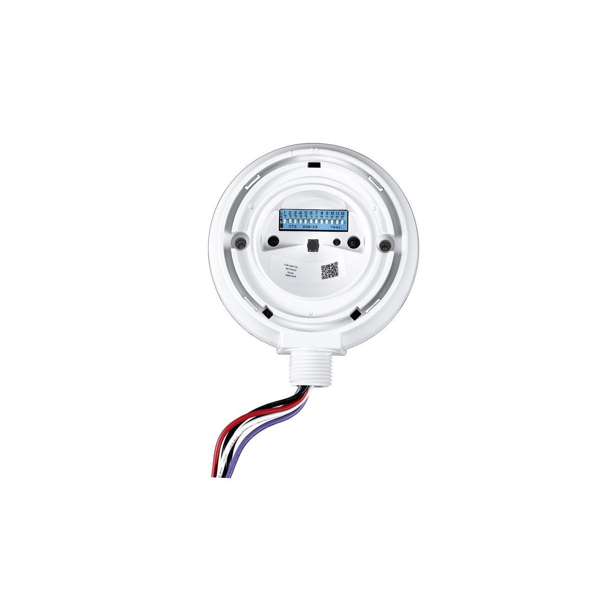
PDF OCCUPANCY SENSOR - hubbellcdn Thread the sensor's wires through the lock-nut. 4. Verify that the sensor is positioned correctly (i.e. facing downward). 5. Screw lock-nut onto the sensor's threaded nipple and tighten. 6. Electrically connect the sensor to the lighting system per the applicable wiring diagram on page 2. 7. Ceiling Motion Sensor Wiring Diagram | Shelly Lighting Ceiling Motion Sensor Wiring Diagram Shelly Lighting June 30, 2018 Motion detectors occupancy sensors wiring diagrams occupancy sensor ceiling mounted ultrasonic occupancy sensor ceiling occupancy sensor wiring diagram
PDF wiHUBB® Occupancy Sensors Installation Instructions Plug wiring harness into connector located on the left side (opposite exit slot) and place wiring under wire tabs (See Figure 6). Align sensor and tighten adjustment screw. 10. Replace sensor cover (See Figure 7). NOTE: LEDs should be on the right. 11. Reapply power at service panel. 12.
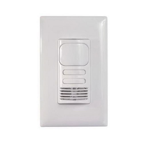
Hubbell occupancy sensor wiring diagram
Stihl Fs 90 Parts Diagram - Wiring Diagram Pictures Liste des pièces. 07/ A Kurbelgehäuse, Zylinder. Crankcase, Cylinder. Carter, Cylindre. Stihl FS 90 R parts list manual. FREE to view or download PDF manual, save or print from all devices. Schematic diagrams and parts numbers for this trimmer. Stihl FS 90 R parts list manual. FREE to view or download PDF manual, save or print from all devices. Ceiling Mount Occupancy Sensor Wiring Diagram | Shelly ... Wrg 4948 Watt Stopper Occupancy Sensor Wiring Diagram 100 Ceiling Mounted Occupancy Sensor Dual Technology Pir Ssiintr003 Wireless Ceiling Mounted Occupancy Sensor User Manual Leviton Ceiling Mount 360 Occupancy Motion Sensor Odc0s I1w 120v Infrared Wall Mounted Occupancy Sensor Installation PDF CONTROL - hubbellcdn These diagrams visually represent occupancy sensor design recommendations based on specific spaces in different building types 8 7 Restrooms are typically occupied less than 50% of the day, but lights are often left ON all the time.
Hubbell occupancy sensor wiring diagram. PDF WASP Occupancy Sensors INSTALLATION INSTRUCTIONS Insert the sensor's wires and threaded nipple into a ½" knockout on the fixture body or an electrical junction box. 3. Thread the sensor's wires through the lock-nut. 4. Verify that the sensor is positioned correctly (i.e. facing downward). 5. Screw lock-nut onto the sensor's threaded nipple and tighten. 6. Asus Rt68u Router Wiring Diagram RT-AC68U AC Dual-Band Gigabit Wi-Fi router: 3X faster than n routers with better Wi-Fi range. AiProtection for enterprise-level security. Step 1: Before you start to setup ASUS AiMesh, be sure to have to have the following devices available: 1. Two ASUS routers which support. No part of this manual, including the products and software described ... PDF LightHawk Wall Switch Occupancy Sensors Installation and ... Wire as shown in the Wiring Diagram section. A secure connection to ground is necessary for the sensor to function properly. 4. Install sensor in wall box using mounting screws provided. 5. Restore power to the sensor and allow it to warm up (up to 2 min.). 6. Remove the sensor's cover - see Adjustments section. 7. Switches and Lighting Controls, Occupancy Sensors ... By Hubbell Wiring Device-Kellems Catalog ID: ATD2000C Switches and Lighting Controls, Occupancy Sensors, Adaptive TechnologyDual (Ultrasonic and PIR) Ceiling Sensors, 2000 Square Feet Coverage Coverage 2000 sq. ft. (360°), low voltage sensor Minimize the risk of false triggering lights turning ON when the space is un-occupied.
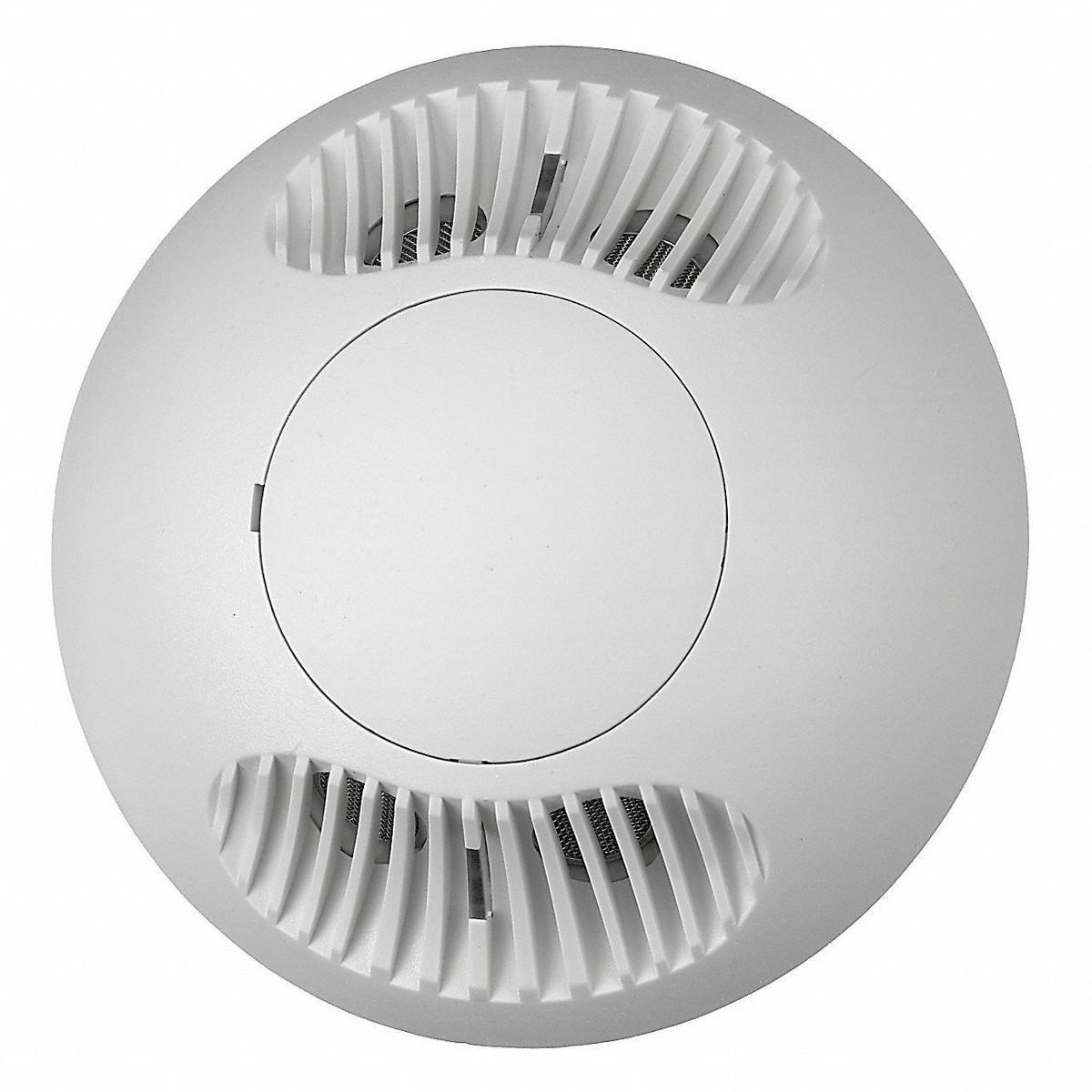
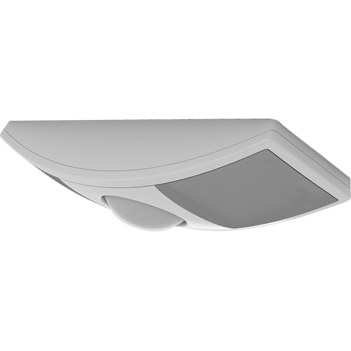
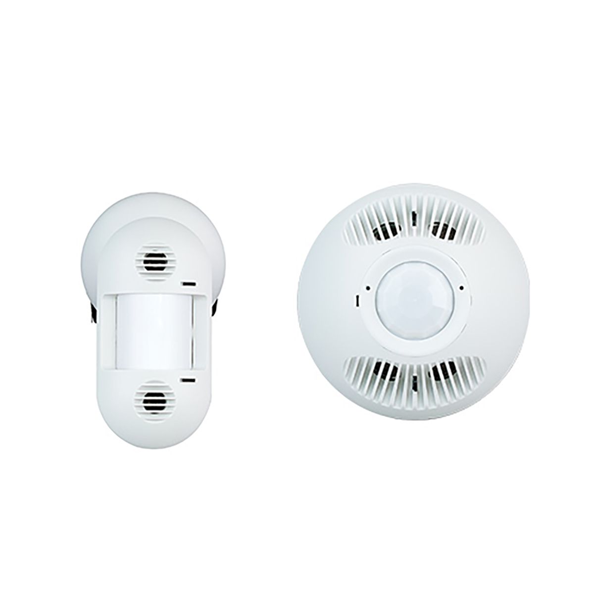
Hubbell Occupancy Sensor Wiring Diagram Database Effectively read a cabling diagram, one offers to learn how the particular components inside the method operate. For example , if a module is usually powered up also it sends out a new signal of fifty percent the voltage plus the technician will not know this, he would think he provides an issue, as this individual would expect a 12V signal. Low Voltage Ultrasonic and PIR Ceiling Sensor - Hubbell The OMNIDT combines ultrasonic (US) and passive infrared (PIR) technologies to turn lighting on and off based on occupancy. This dual technology provides accurate turn-ons while virtually eliminating false-offs. This sensor features Hubbell Control Solutions' patented IntelliDAPT technology, which makes all the sensor adjustments automatically. Throughout the product's lifespan, smart software ... Campbell Hausfeld Ultra Pal Air Compressor 2 Hp Wiring Diagram Sick Microscan 3 Ponz Safety Relay Wiring Diagram; Xlr To 1/4 Inch Mono Wiring Diagram; 2012 Corvette 7.0 Starter Wiring Diagram; Hubbell Occupancy Sensor Wiring Diagram; John Deere La175 Wiring Diagram; 18 Hp Briggs Charging Wiring Diagram Diode; Ef Falcon Wiring Diagram; Parallelogram Steering Diagram; Recent Comments. Silas L. on Campbell ... Hubbell Lighting Resources : Instruction Sheets NX High Mount Outdoor Sensor Module - NXSMP-HMO_LMO_Installation_Sheet.pdf. NX Slide Mount Indoor Sensor Module - NXSMP-SMI_Installation_Sheet.pdf. NX HubbNET™ Radio Module - NXRM-H_Installation_Sheet.pdf. RJ45 Adapter and CAT5 System Cables - RJ45 Adapter Installation Instructions.
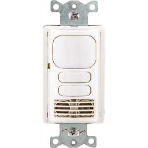
Dmx Cat5 Wiring - Wiring Diagrams The following table is shows the ANSI E standard DMX pinout when using Category 5 (or higher) wire and an RJ45 connector: Wire Color and # Function. Equivalent XLR Pin # 1 - White/Orange. Data + (Pair 1 True) 3. DMX-5XM-CAT5 5-Pin XLR Male To RJ45 Adapter-by-Tecnec. by Tecnec. $ $ 8 01 + $ shipping. out of 5 stars 8. PDF Hubbell Occupancy Sensors - Womack Electric Hubbell AT1277 and ATP1277 series wall switch occupancy sensors utilize passive infrared technology to determine occupancy. These sensors require line of sight to detect body heat in motion. Wall switch occupancy sensors are best suited for small enclosed spaces such as offices, conference rooms, storage closets, small lunch rooms and copy rooms. Occupancy Sensors - Hubbell Control Solutions Instruction Sheets Specification Sheets Wiring Diagrams. Building Information Modeling (BIM) Files Customer Use Drawings. ... Hubbell Lighting Brands. ... -savings while reducing maintenance costs by Maximizereplacing standard switches with LightHAWK® Wall Mount Vacancy/Occupancy Sensors. Compare. View Details. Resource Quick View. Check ... PDF OCCUPANCY SENSORS AND CONTROLLERS - Royal Electric OCCUPANCY SENSORS AND CONTROLLERS PROJECT INFORMATION Project Name Catalog No. Date End Mount WASP2 Sensor ... Wiring Diagram 24V WASP2 Wiring Diagram 9601 Dessau Road | Building One | Austin, Texas 78754 | 512-450-1100 | 512-450-1215 fax | 2101A 5.10.2016 Example: WSP EM UNV - Wasp End Mount Sensor, 120-347VAC ...
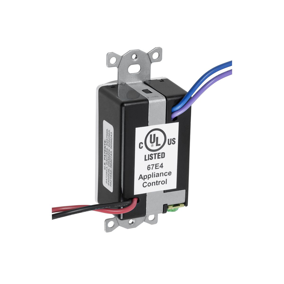
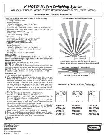
Hubbell Occupancy Sensor Wiring Diagram Wire the sensoras shown in the wiring diagram: The BL CK. The WSW is a passive infrared wall switch Occupancy Sensor combines PIR sensing technology, photocell control and Hubbell's patented three wire.mounting diagrams. SURFACE MOUNT SENSOR INSTALLATION 1. Turn power off at the service panel before installing sensor. 2.
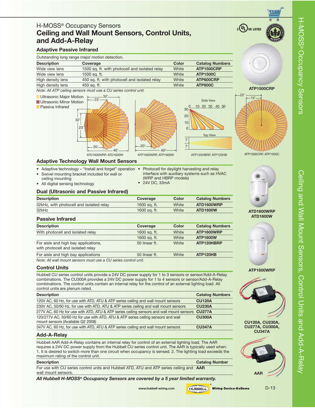
PDF Section E H-MOSS Controls - Steven Engineering Ultrasonic (US) technology senses occupancy by bouncing sound waves (32 kHz - 45 kHz) off of objects and detecting a frequency shift between the emitted and reflected sound waves. Movement by a person or object within a space causes a shift in frequency, which the sensor interprets as occupancy.
Es335 Wiring Kit - Wiring Diagrams This kit is a complete electrical replacement for any Gibson or Epiphone ES, ES copy or any guitar with a standard ES layout. 50's Wiring: This kit is. Prewired harness to suit Gibson® or Epiphone® ES ®, ES ®, Dot and Casino style guitars. The perfect upgrade to imported far eastern models, this. ES Wiring Kit - available online from ...
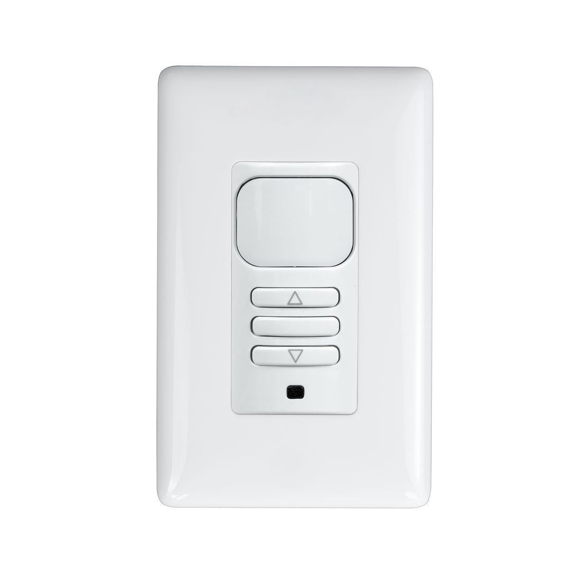
Lighting Controls, Vacancy/Occupancy Sensors ... - Hubbell By Hubbell Wiring Device-Kellems. Catalog ID: WS1000W. Lighting Controls, Vacancy/Occupancy Sensors, Wall Switch, Passive Infrared Technology, Single Circuit, 120V AC, 500 Watt, White. No Neutral; Contact Us. Add to List. × Add to Project List ...
Hubbell Lighting Resources : Specification Sheets OMNI Ceiling Mount Vacancy/Occupancy Sensor Product Line - OMNI-BP DIA Spec Sheet. PHDIM-1277 - HCS PHDIM Dimming Converter Specification Sheet. NX Room Controller - NX Room Controller Spec Sheet. NX Lighting Control Panels 8,16,24, 32 and 48 Relays - NX Panel Specification Sheet. NX Lighting Control Panels 8,16,24, 32 and 48 Relays - HCS_3460A ...
Lighting Controls, Occupancy/Vacancy Sensors ... - Hubbell By Hubbell Wiring Device-Kellems Catalog ID: WS2000W Lighting Controls, Occupancy/Vacancy Sensors, Wall Switch, Passive Infrared Technology, 120/277V AC, White Designed for use on 120 or 277V AC circuits, no neutral required, fast retrofits. Built in photocell prevents lights from turning ON with sufficient natural light. 3-Way capable
PDF Vacancy Sensor Wiring Diagram Vacancy Sensor Wiring Diagram Common Source Manual ON Power 24V DC + Control ... Audible Alert 7 Visible Alert 8 Hold ON 9 ON OFF. MPC-50L Passive infrared Occupancy Sensü, *24VDC connect to MPP-24 or any other Class 2 Power Packs For Indoor use Only Revolution Lighting . Author: Joe Herbst Created Date:
PDF Passive Infrared / Ultrasonic Occupancy Sensors Wire as shown in the Wiring Diagram section. A secure connection to ground is necessary for the sensor to function properly. 4. Install sensor in wall box using mounting screws provided. 5. Restore power to the sensor and allow it to self adjust (up to 2min.). Lights may be off during this time. 6.
PDF WASP2 Occupancy Sensor OCCUPANCY SENSORS AND CONTROLLERS PROJECT INFORMATION Project Name Catalog No. Date End Mount WASP2 Sensor ... Wiring Diagram 24V WASP2 Wiring Diagram 9601 Dessau Road | Building One | Austin, Texas 78754 | 512-450-1100 | 512-450-1215 fax | 2101A 01.13.2016 Example: WSP EM UNV - Wasp End Mount Sensor, 120-347VAC ...
PDF CONTROL - hubbellcdn These diagrams visually represent occupancy sensor design recommendations based on specific spaces in different building types 8 7 Restrooms are typically occupied less than 50% of the day, but lights are often left ON all the time.
Ceiling Mount Occupancy Sensor Wiring Diagram | Shelly ... Wrg 4948 Watt Stopper Occupancy Sensor Wiring Diagram 100 Ceiling Mounted Occupancy Sensor Dual Technology Pir Ssiintr003 Wireless Ceiling Mounted Occupancy Sensor User Manual Leviton Ceiling Mount 360 Occupancy Motion Sensor Odc0s I1w 120v Infrared Wall Mounted Occupancy Sensor Installation
Stihl Fs 90 Parts Diagram - Wiring Diagram Pictures Liste des pièces. 07/ A Kurbelgehäuse, Zylinder. Crankcase, Cylinder. Carter, Cylindre. Stihl FS 90 R parts list manual. FREE to view or download PDF manual, save or print from all devices. Schematic diagrams and parts numbers for this trimmer. Stihl FS 90 R parts list manual. FREE to view or download PDF manual, save or print from all devices.











0 Response to "38 hubbell occupancy sensor wiring diagram"
Post a Comment