40 iron nickel phase diagram
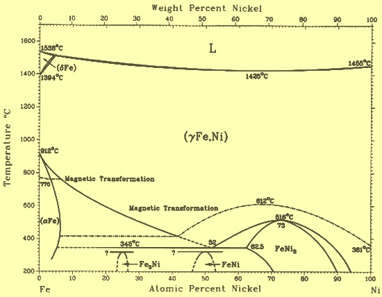
Phase relations of iron and iron-nickel alloys up to 300 ... On the other hand, the incorporation of nickel has a remarkable effect on expanding the stability field of fcc phase. The geometry of the temperature-composition phase diagram of iron-nickel alloys suggests that the hcp-fcc-liquid triple point is located at 10 to 20 wt.% Ni at the pressure of the inner core boundary. PDF Chapter 7 Alloys with Nickel 7.1. Al-Fe~Ni PHASE DIAGRAM This phase diagram can be used for the analysis of the phase composition of an 8001 alloy (Table 7.1) that contains only nickel and iron as the alloying elements. This phase diagram is also necessary for the analysis of more complex systems. In the Al-Fe-Ni ternary system, the AlsFe, AlsNi, and AIQECNI phases are
Allotropes of iron - Wikipedia The primary phase of low-carbon or mild steel and most cast irons at room temperature is ferromagnetic α-Fe. It has a hardness of approximately 80 Brinell. The maximum solubility of carbon is about 0.02 wt% at 727 °C (1,341 °F) and 0.001% at 0 °C (32 °F). When it dissolves in iron, carbon atoms occupy interstitial "holes". Being about twice the diameter of the tetrahedral hole, the carbon ...

Iron nickel phase diagram
The Formation of Ferrite in Iron-nickel Meteorites Figure 2.6: The iron-nickel phase diagram, which includes terminology describing meteorites of specific Ni concentrations. i.e. a medium octahedrite is an iron meteorite which contains 6.5 - 10.5 Ni wt %. Also, this figure shows the nickel percentages often found associated with PDF The Iron-nickel-tungsten Phase Diagram In the iron-tungsten binary ,(2) there are two intermediate phases, WFe2 and W2Fe3. Winkler and Vogel show only W2Fe3. In the iron-nickel binary, no new phases except an ordered phase, Fet'-li3, have been reported. Further work on the delt.o ferrite portion of the diagram, however, has significantly changed the phase bound aries. Iron-Carbon Phase Diagram Explained [with Graphs] - Fractory For example, in the iron carbon phase diagram, addition of nickel lowers the A3 boundary while the addition of chromium raises it. Eutectic Point. Eutectic point is a point where multiple phases meet. For the iron-carbon alloy diagram, the eutectic point is where the lines A1, A3 and ACM meet. The formation of these points is coincidental.
Iron nickel phase diagram. A magnetic study of the two-phase iron-nickel alloys. II magnetic properties of the two-phase iron-nickel alloys. Magnetic measurements showed the existence of a two-phase field and the phase diagram above 450° C was determined. The relations between the magnetization temperature curves and phase changes suggested that the magnetic method of investigating the phase PDF I i FE-NI PHASE DIAGRAM - NASA The new phase diagram proposed from the results of this work is shown in Figure 4, high temperatures. below 500°C and a maxim Ni content of approximately 7 At$ Ni is ... nickel is soluble in alpha-iron-nickel alloys than indicated by the presently accepted diagram. The Co−Ni (Cobalt-Nickel) system - Journal of Phase ... Indicates key paper. 79Tom: J. Tomiska, H. Nowotny, L. Erdelyi, and A. Neckel, "Thermodynamic Studies of the Cobalt-Nickel System: Mass Spectrometric Activity Measurements in the Liquid and Solid Phase and Calculation of the Melting Diagram",Ber. Bunsenges. PDF Chapter 9: Phase Diagrams - Florida International University Phase Diagrams • Indicate phases as function of T, Co, and P. • For this course:-binary systems: just 2 components.-independent variables: T and Co (P = 1 atm is almost always used). • Phase Diagram for Cu-Ni system Adapted from Fig. 9.3(a), Callister 7e. (Fig. 9.3(a) is adapted from Phase Diagrams of Binary Nickel Alloys , P. Nash
[PDF] Iron--Nickel--Tungsten Phase Diagram. | Semantic Scholar In support of a study of the properties of liquid-phase-sintered iron-nickel-tungsten alloys, the most probable phase diagram was drawn. The space diagram is shown as a series of isothermal sections between 1,650 and 800° C and a liquidus and solidus projection. (PDF) Fe-Ni-Si (Iron-Nickel-Silicon) | Vijayaraghavan ... Section II: Phase Diagram Evaluations JPEDAV (2010) 31:184-185 DOI: 10.1007/s11669-010-9653-4 1547-7037 ÓASM International Fe-Ni-Si (Iron-Nickel-Silicon) V. Raghavan The review of this system by [1988Ray] presented a an ordered phase FeNi3 (L12, AuCu3-type cubic) forms tentative liquidus projection, partial isothermal sections at congruently from c. Phase Relationships in The Nickel-zirconium and Nickel ... The phase diagram for the nickel- zirconium alloy system was established through solidus and liquidus temperature determinations, temperature vs resistance measurements, metallographic examinations, and x-ray diffraction investigations. The intermediate phases Ni/sub 11/Zr/sub 9/, Ni/sub 10/ Zr/sub 7/ , Ni/sub 5/ Zr/sub 2/. and Ni/sub 5/Zr are ... PDF Iron-Nickel Alloy in the Earth's Core The phase relations of an Fe10wt%Ni alloy were investigated in a diamond anvil cell up to 86 GPa and 2382 K. Adding nickel into iron stabilizes the fcc phase to higher pressures and lower temperatures compared to pure iron, and a region of two-phase coexistence between fcc and hcp phases is observed.
Phase-diagram Study of Alloys in The Iron-chromium ... osti.gov journal article: phase-diagram study of alloys in the iron-chromium-molybdenum-nickel system The Fe-Ni (iron-nickel) system | SpringerLink In Vol. 12, No. 3, page 301 ("The Fe-Ni (Iron-Nickel) System," by L.J. Swartzendruber, V.R Itkin, and C.B. Alcock), in Table 6 three figures contained incorrectly placed decimal points. In the first line following the subhead "bcc phase," 11 736.4 should be 127 364. In the first line following the subheading "fcc phase," 11 274 ... A Magnetic Study of the Two-Phase Iron-Nickel Alloys The relation of the irreversible changes to the equilibrium phase diagram is not clearly understood. Recently, however, equilibrium diagrams of the iron-nickel system, determined by means of X-ray data, have been pub-lished by Bradley and Goldschmidt (I939) and Owen and Sully (I939). An X-Ray Study of the Iron-Nickel-Aluminium Ternary ... The general result of the X-ray work is to confirm the phase diagram given by Merica (i93o), which is given in fig. 1. This shows the existence of two phase fields, one face-centred cubic stretching from pure nickel towards the iron end of the diagram, and the other body-centred. The iron-nickel-aluminitum ternary equilibrium diagram 355 cubic ...
Figure 3 from Elastic Properties of Metals and Alloys, I ...
PDF Iron-Nickel alloy in the Earth's core [8] Compared to the phase diagram of pure Fe [Hemley and Mao, 2001], it is evident that the stability field of the fcc phase can be extended to higher pressures and lower temperatures with the addition of Ni (Figure 1). However, the effect of Ni on the phase diagram of Fe is not as dramatic as the addition of silicon in Fe [Lin et al., 2002].
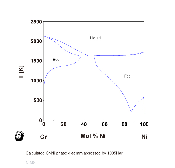
Cr-Ni (NIMS)
Iron--Nickel--Tungsten Phase Diagram. - UNT Digital Library Iron--Nickel--Tungsten Phase Diagram. Showing 1-4 of 25 pages in this report. PDF Version Also Available for Download. Physical Description. 21 p. Creation Information. Winslow, F. R. January 1, 1971. Context ...
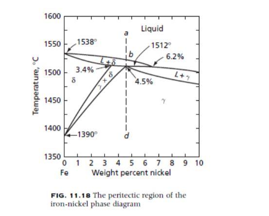
Solved What phases are in equilibrium at the peritectic ...
PDF Chapter Outline: Phase Diagrams We will limit our discussion of phase diagrams of multi-component systems to binary alloys and will assume pressure to be constant at one atmosphere. Phase diagrams for materials with more than two components are complex and difficult to represent. An example of a phase diagram for a ternary alloy is shown for a fixed T and P below.
Fe (Iron) Binary Alloy Phase Diagrams
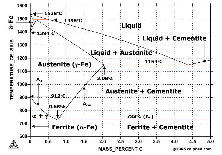
Iron-Carbon Diagram Explanation [PDF] - Mechanical E-Notes Iron-Carbon Phase Diagram with Detailed Explanation: If the percentage of the carbon is in the range of 0 to 2.11 % then it is called Steel and if the percentage of carbon is in the range of 2.11 to 6.67% then it is called Cast iron. As the carbon content increases, it produces more Iron-Carbide volume and that phase will exhibit high hardness.
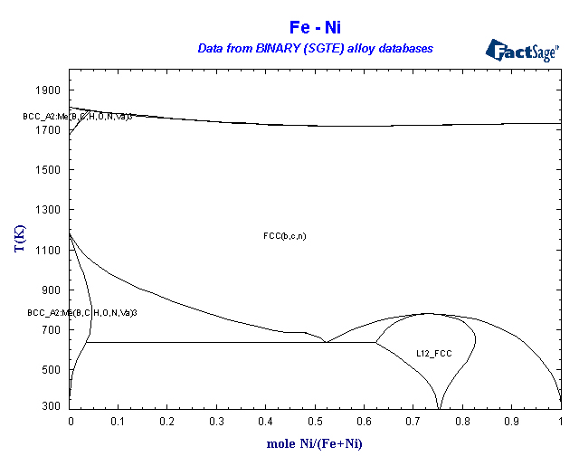
BINARY (SGTE) Alloy Phase Diagrams
The Iron-Carbon Alloys And Fe-C Phase Diagram - MD ... The iron-carbon phase diagram and the iron-carbon systems are the most important binary systems in engineering. Steels, cast irons, and various kinds of applications are dependent on iron-carbon systems. We also explained the tin-lead phase diagram and nickel-copper phase diagrams which are also very important in metallurgy and engineering. In ...

PDF) Fe-Ni-Si (Iron-Nickel-Silicon) | Vijayaraghavan ...
An X-ray study of the iron-nickel-aluminium ternary ... The general result of the X-ray work is to confirm the phase diagram given by Merica (1930), which is given in fig. 1. This shows the existence of two phase fields, one face-centred cubic stretching from pure nickel towards the iron end of the diagram, and the other body-centred. The iron-nickel-aluminium ternary equilibrium diagram 355
Thermodynamics at the nanoscale: phase diagrams of nickel ...
PDF Fe-ni phase diagram - NASA Technical Reports Server (NTRS) Fe-ni phase diagram Alpha and gamma solubility limits in iron-nickel phase diagram at high temperatures - quench- and-anneal and diffusion couple techniques and electron probe microanalysis. Document ID. 19650020214. Document Type. Technical Memorandum (TM) Authors. Goldstein, J. I. (NASA Goddard Space Flight Center Greenbelt, MD, United States)

Austenitic Steels :: Total Materia Article
Fe-Ni phase diagram. [16] | Download Scientific Diagram Download scientific diagram | Fe-Ni phase diagram. [16] from publication: Synthesis by hydrogen reduction and characterization of iron nickel alloys | Iron nickel alloy has been prepared from the ...
Solution for Homework Assignment #4
PDF Iron-Nickel Alloy in the Earth's Core Iron-nickel (Fe-Ni) alloy is the most abundant component in the Earth's core [1]. The amount ofNi in the core is about 5.5wt%, on the basis of geochemical models [2]. The phase diagram and physical properties of Fe have been extensively studied [3]. Iron crystallizes in the bcc structure under ambient conditions, and it
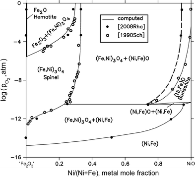
Fe-Ni-O (Iron-Nickel-Oxygen) | SpringerLink
Cobalt - Iron - Nickel | Request PDF - ResearchGate The relation of the depth of chroming of iron-chrome-nickel alloys to the structure of an isothermic section of the ternary phase diagram has been indicated. 2.
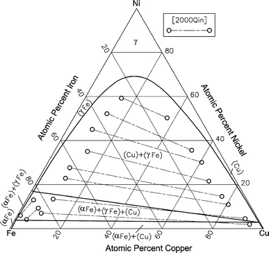
Cu-Fe-Ni (Copper-Iron-Nickel) | SpringerLink
Iron-Carbon Phase Diagram Explained [with Graphs] - Fractory For example, in the iron carbon phase diagram, addition of nickel lowers the A3 boundary while the addition of chromium raises it. Eutectic Point. Eutectic point is a point where multiple phases meet. For the iron-carbon alloy diagram, the eutectic point is where the lines A1, A3 and ACM meet. The formation of these points is coincidental.

Iron-Nickel Alloys - an overview | ScienceDirect Topics
PDF The Iron-nickel-tungsten Phase Diagram In the iron-tungsten binary ,(2) there are two intermediate phases, WFe2 and W2Fe3. Winkler and Vogel show only W2Fe3. In the iron-nickel binary, no new phases except an ordered phase, Fet'-li3, have been reported. Further work on the delt.o ferrite portion of the diagram, however, has significantly changed the phase bound aries.

Binary Alloys - an overview | ScienceDirect Topics
The Formation of Ferrite in Iron-nickel Meteorites Figure 2.6: The iron-nickel phase diagram, which includes terminology describing meteorites of specific Ni concentrations. i.e. a medium octahedrite is an iron meteorite which contains 6.5 - 10.5 Ni wt %. Also, this figure shows the nickel percentages often found associated with

Electroplating and characterization of cobalt–nickel–iron and ...
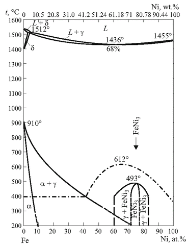
Compilative Fe – Ni phase diagram with author's correction ...
phase diagram iron carbon | Metallurgy for Dummies

File:Iron-titanium phase diagram.png - Wikiversity

Fe-Ni phase diagram calculated thanks to the optimizations of ...
Nickel in Steels – IspatGuru

Experimentally obtained “metastable” phase diagram of Ni–Fe ...

Determination of the iron rich portion of the iron - nickel ...
![The Fe-Ni phase diagram from a literature [26]. | Download ...](https://www.researchgate.net/publication/272879847/figure/fig2/AS:615086280413192@1523659405670/The-Fe-Ni-phase-diagram-from-a-literature-26.png)
The Fe-Ni phase diagram from a literature [26]. | Download ...
![Iron-Carbon Phase Diagram Explained [with Graphs]](https://fractory.com/wp-content/uploads/2020/03/Iron-carbon-phase-diagram-explained.jpg)
Iron-Carbon Phase Diagram Explained [with Graphs]

File:Fe-Cr Phase Diagram.gif - Wikiversity

Influence of Alloying Elements on Steel Microstructure ...
Processes | Free Full-Text | On the Application of the ...
Short Course Notes

Magnetic phase diagram of the Fe–Ni system - ScienceDirect

Iron-Nickel Alloys - an overview | ScienceDirect Topics
metallurgy - Schaeffler, De Long, and WRC welding diagrams ...
Solved: Consider an Fe−4.2 wt % Ni alloy (Fig. 8.17) that is ...
![Fe-Ni phase diagram. [16] | Download Scientific Diagram](https://www.researchgate.net/profile/Rcs-Navarro/publication/286807012/figure/fig3/AS:587504373760005@1517083366669/Fe-Ni-phase-diagram-16.png)
Fe-Ni phase diagram. [16] | Download Scientific Diagram

Phase relations in the system Fe–Ni–Si to 200 GPa and 3900 K ...

Figure 7 from Iron--Nickel--Tungsten Phase Diagram ...
Chapter 8 Phase Diagrams

Materials Engineering - ppt download
Teach Yourself Phase Diagrams and Phase Transformations
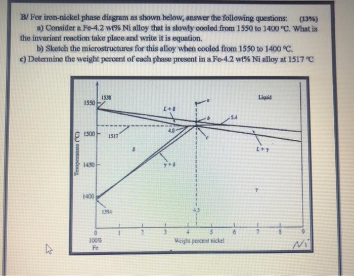
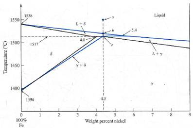
Solved B/ For iron-nickel phase diagram as shown below ...

Equilibrium phase diagram for Iron-Nickel-Chromium alloy ...
1 a)Aluminum Nickel Phase diagram b)Aluminum Iron Phase ...
0 Response to "40 iron nickel phase diagram"
Post a Comment