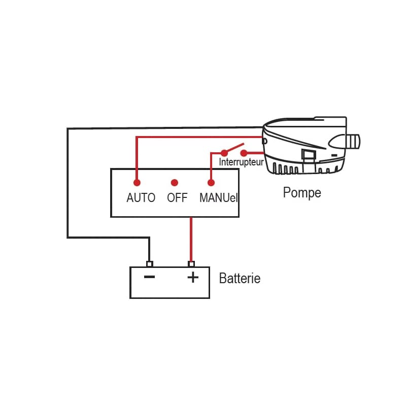
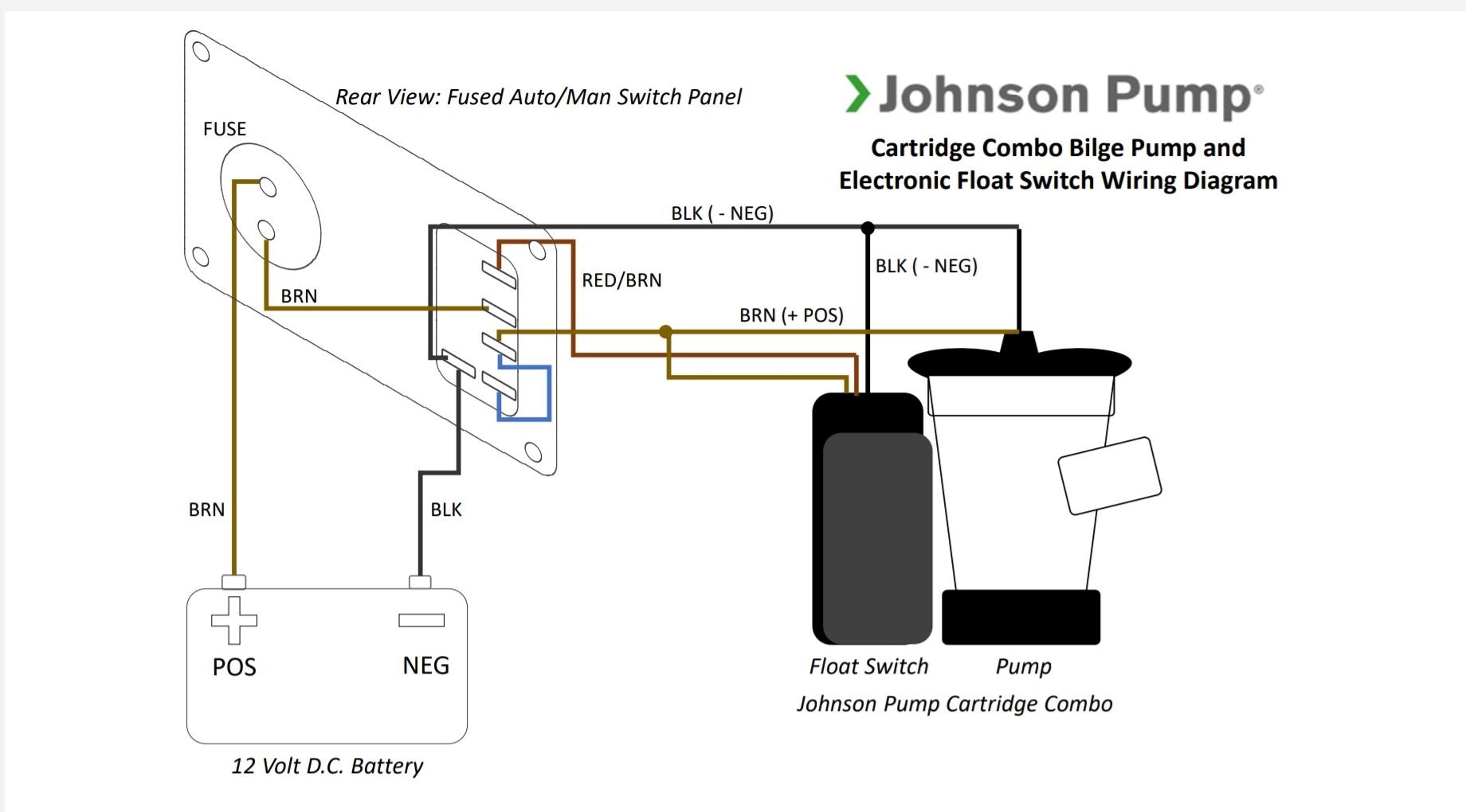
40 johnson bilge pump wiring diagram
Rule Mate Bilge Pump Wiring - diagramweb.net Rule's non-automatic cartridge series bilge pumps offer traditional operation activated by a float or panel switch. Removal of the motor cartridge allows for easy cleaning of the strainer and impeller if clogged with debris.The Marine Installer's Rant: Johnson bilge pump wiring, "Splained to Lucy."Rule Pumps, Water Pumps - diagramweb.net Installing a Bilge Pump - BoatUS Run the wires up and secure them so that they do not sag into the bilge water. Don't skimp on wire size A 3,500 gph pump will draw 15 amps, typically necessitating 10-gauge, or maybe even 8-gauge wire. Consult the ABYC Wire Size Table to determine the appropriate wire for your pump and length of wire run. Use butt connectors and heat shrink
Johnson bilge pump wiring - cable woes | YBW Forum This mess, in diagram, looks like this (also up-side-down): The pump has a lead with 3 wires, so I am ok with re-attaching wires #2, #5 and #6. It was working before, in both auto and manual, so I should be fine.The + and - are noted and ok. What about WIRE #4 (seen at bottom of diagram)?

Johnson bilge pump wiring diagram
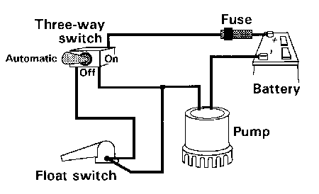
Mayfair Bilge Pump Wiring Diagram | Manual E-Books - Bilge ... According to previous, the traces at a Bilge Pump Float Switch Wiring Diagram represents wires. Sometimes, the cables will cross. However, it doesn't imply connection between the wires. Injunction of 2 wires is generally indicated by black dot in the junction of two lines. There will be main lines that are represented by L1, L2, L3, and so on. Mayfair Bilge Pump with Float wiring diagram | Boating ... I wanted to post this wiring diagram (simply drawn), for all the folks that have trouble following written directions for wiring a Mayfair Bilge Pump with Electronic Float Control. This is wired to an indash switch so it works with the manual switch and it works automatically when the switch is off. Hope you dont mind my artistry! Attachments Johnson Pump Float Switch - YouTube About Press Copyright Contact us Creators Advertise Developers Terms Privacy Policy & Safety How YouTube works Test new features Press Copyright Contact us Creators ...
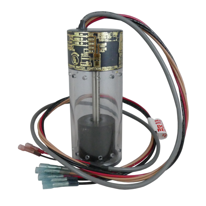
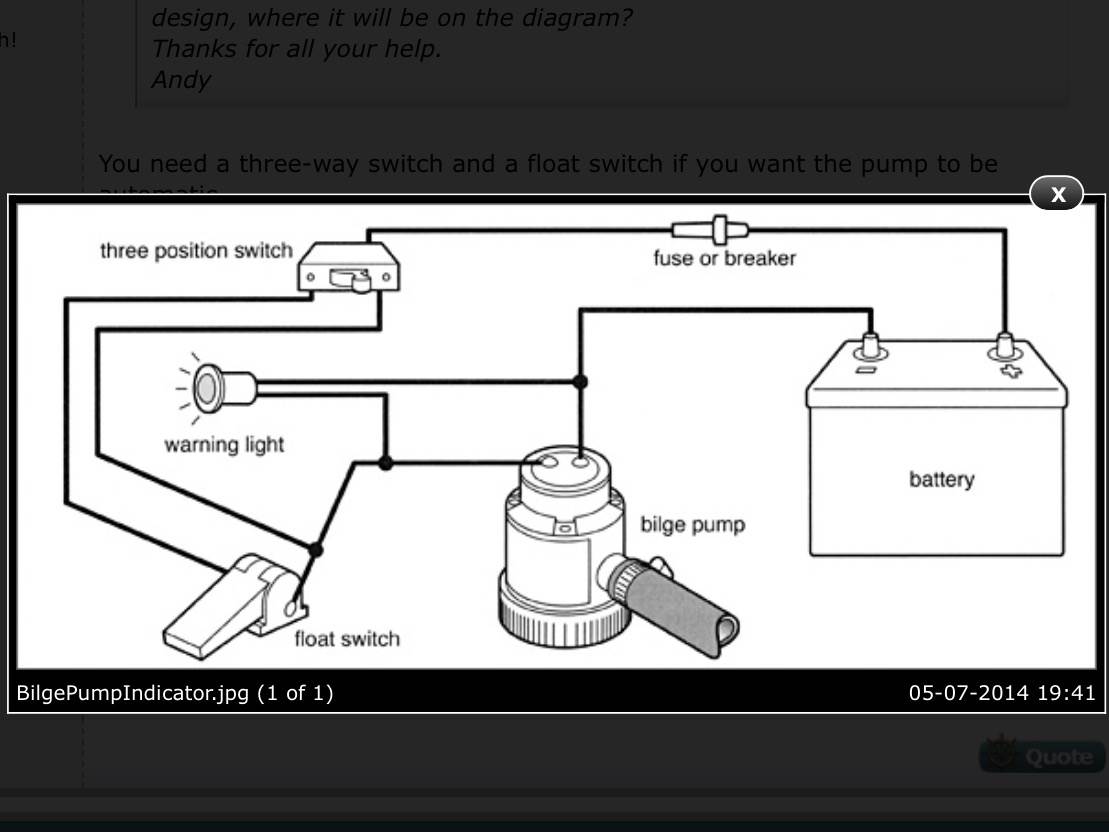
Johnson bilge pump wiring diagram. Amazon.com : Johnson Pumps 72303-001 Bilge Alert High ... If you have the small, wafer-style sensor (approx. 1 inch wide x 2 inches long), both it and the panel switch should have a black/red/white wire. If you have the Ultima switch, it would only have a brown and brown/white wire, and so would the panel switch. 3 Way Bilge Pump Switch Wiring Diagram at Wiring I am having trouble wiring a johnson 3 wire electronic float switch to a 3 way switch with manual off and automatic bilge pump operation. 3 way bilge pump switch wiring diagram. There's also a cool feature of wiring your bilge pump float switch like this: If not the arrangement will not work as it ought to be. Johnson Ultima Bilge Pump Wiring Diagram - 4K Wallpapers ... Johnson Ultima Bilge Pump Wiring Diagram Buy Johnson Pump Spx Flow Ultima Combo Bilge Pump 750gph 12v 12v Online In Vietnam B005uzi11u. Previous Next. Suggested Wallpapers: Johnson Ultima Bilge Pump Wiring Diagram Pdf, Related Gallery: ... PDF Automatic Bilge Pump Switch - Seachoice bilge pump. • Always install the switch according to wiring diagram (see illustration #2 and #3) • The wire connections must be sealed with a marine sealant. • Insulation or cable sheathings must be placed above the highest bilge water level. Installation The switch is designed to attach the SPX FLOW Johnson Pump Cartridge bilge pump.
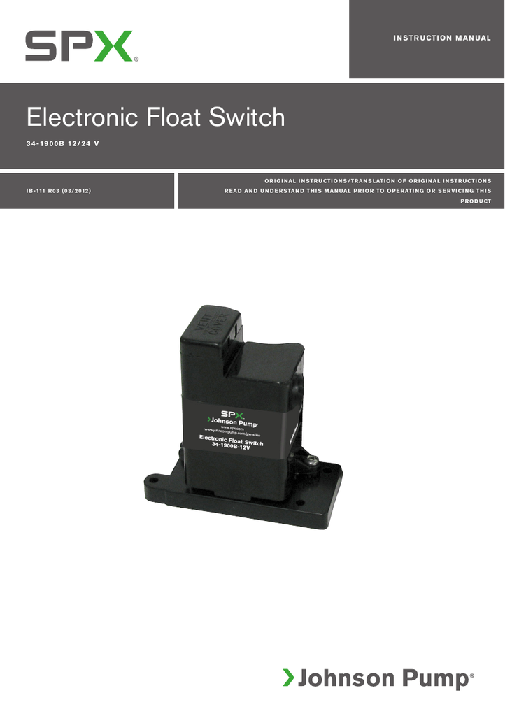
Johnson Bilge Pump Float Switch Wiring Diagram - 4K ... Johnson Bilge Pump Float Switch Wiring Diagram Tponwa. Previous Next. Suggested Wallpapers: Johnson Bilge Pump Float Switch Wiring Diagram, Related Gallery: Three Speed Fan Wiring Diagram | 74 Vw Bug Wiring Diagram | Best House Wiring Book | 7 Way Wiring Diagram | Wiring Diagram Coleman Mach Thermostat | Cat 7 Rj45 Wiring | 99 Jeep Grand Cherokee Tail Light Wiring Diagram | Wemo Light Switch ... PDF 52229 R01 Installation Instructions: Read and ... - Spx Flow bilge pump. • Always install the switch according to wiring diagram (see illustration #2 and #3) • The wire connections must be sealed with a marine sealant. • Insulation or cable sheathings must be placed above the highest bilge water level. Installation The switch is designed to attach the SPX FLOW Johnson Pump Cartridge bilge pump. photokrattphie-baby.de There are also four wires on this timer base; white, purple, blue & green. outboard motor, 1978 johnson 70 hp operation, wiring diagram for 1987 Evinrude 70 HP, Johnson 35 HP manual, 1968 65 HP Johnson outboard, wiring diagram for tilt and trim motor, Johnson Evinrude thermostat 5-235HP, 1973 - 1989 Johnson outboard repair, owner and part manual, 55. Quick … PDF Installation Instructions Automatic Bilge Pump 1. Use 16 Gauge marine-grade tinned wire. 2. Connect Brown wires as noted below. 3. Black (-) wire is negative and connects to the negative terminal of the battery. 4. Install a 5 amp fuse in the brown wire as near as possible to the battery. TRAC Automatic Bilge Pumps can be wired one of (3) three ways depending on your preference. We recommend
Johnson Pump Marine - SPX FLOW Serving both leisure and commercial vessels, Johnson Pump Marine manufactures high-efficiency products for either initial OEM fitting-out or subsequent after-market installation. Among these items are bilge pumps, fuel transfer pumps, engine cooling pumps, circulation pumps, emergency pumping equipment, clutch pumps, wastewater and toilet ... Johnson Bilge Pump Wiring Diagram With Float Switch Mar 31, · 3) The brown wire from the float switch connects to both the brown wire on the bilge pump and the 2nd 12VDC source from manual switch they show. (you will need to provide power to the other side of the manual switch) 4) Battery Negative connects to both the Float switch Black AND pump Black wires. Johnson Bilge Pump Wiring Diagram With Float Switch • Always install the switch according to the wiring diagram on pages the highest bilge water level. The UltimaSwitch™ is designed to attach to all Johnson. wiring johnson bilge pump The Salty Dogs. put a switch according to the diagram how will the pump get power from the float switch is this just. Johnson Pump 1600 Gph Bilge Pump 1-1/8" Hose 12v Johnson Pump 1600 Gph Bilge Pump 1-1/8" Hose 12v. designed to meet and exceed the tough demands of commercial and recreational duty. This pump has a liquid cooled, 12-pole motor with double ball bearings for extended service life. The 2200 motor is sealed off by a mechanical seal design, while the 1600 model has lipseal.
How to Wire a Bilge Pump (with Pictures) - wikiHow Fasten the bilge pump with brackets or use epoxy to attach bolts to the bilge bottom, which then serve as mounting studs. 3 Mount the float switch. 4 Connect the pump to the discharge using a hose with a smooth interior. Hoses sold with a corrugated interior can reduce water output by as much as 30 percent. 5
Needing a wiring diagram for a Johnson 3-wire electronic ... I am having trouble wiring a Johnson 3-wire electronic float switch to a 3-way switch with Manual, off, and automatic bilge pump operation. I need to see a wiring diagram and then I can wire the components together. I wired what I thought was correct and tried to test the float switch by holding the float up with no water. It seems that should ...
How do you wire a bilge pump? We wire up manual and ... How do you wire a bilge pump? We show how to wire in a manual 12V bilge pump, and wire an automatic bilge pump with a Seaflo bilge pump switch. Whether you...
Formidable Bilge Pump Switch Wiring Obd0 Engine Harness ... It includes guidelines and diagrams for different varieties of wiring strategies as well as other things like lights home windows etc. Rule bilge pump float switch wiring diagram source. Connect the pump to the discharge using a hose with a smooth interior. Steps for wiring bilge pump with float switch 1. All circuits are the same.
Dealership Showcased. 00. Runs No longer available. 1000s ... Because Chrysler engineers chose to make the electronic ignition system a drop-in replacement when it was introduced, it is very easy to adapt it to earlier vehicles or those Buy OEM Parts for Chrysler Outboard 25HP CARBURETOR Diagram Buy your Mercury outboard motor parts online from experienced boat specialists at Van's Sport Center! Mercury | CHRYSLER | 15 (1976) | …
Heartwarming Bilge Pump With Float Switch Wiring Diagram ... Bilge pump float switch wiring diagram you ll need an extensive expert and easy to comprehend wiring diagram. Mar 30 wiring johnson bilge pump the salty dogs. Mayfair bilge pump with float wiring diagram thats a great diagram. Ensure they are restrained so they don t fall and get damaged as they intake air 2. With this sort of an illustrative ...
How to wire a bilge pump | ON-OFF bilge switch | New Wire ... Let's look at a few schematics both with bilge pumps wired with a float switch: Manual Only Bilge Switch With a manual bilge switch - our recommended way - the float switch is always connected straight to the battery via a fuse. It cannot be turned off by the helm bilge switch. Manual / Auto Bilge Switch
Best Bilge Pump Switch Wiring Diagram Pioneer Radio ... The diagrams show conection of brown pump wire to float switch and an intemediary. 3 backlit bilge rocker switch wiring diagram. Turns out the johnson float switch was not activating the pump. Use brackets to fasten bilge pump or with epoxy so you can attach bolts at the bottom of the bilge that will be the mounting studs.
PDF Auto Bilge Pump Installation Instructions Auto Bilge Pump ... While installing, connect the pump's black wire to the negative (-) terminal and brown or brown white wire to the positive pole (+). Use the suitable fuse. The wire connections must be sealed by marine sealant. All wires and connections must be above the bilge water level. Unless necessary,please do not arbitrarily remove the insulator.
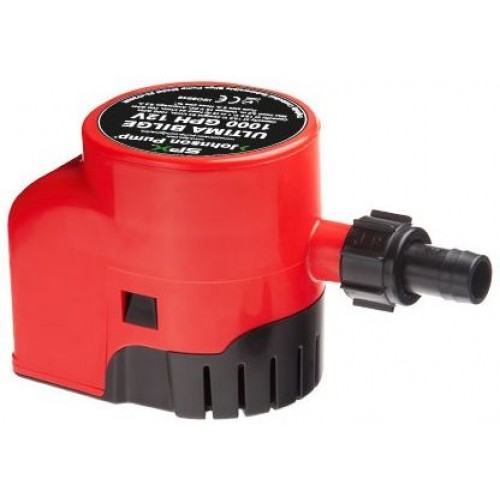
Johnson Ultima Bilge Pump Wiring Diagram - Wiring Diagram Ultima Bilge Automatic Submersible Pumps. Johnson bilge pump wiring cable woes advice the hull ultima switch electronic float spx flow 1600 gph water 3 way panel for 600gph 2280l h only pumps 32 47261 002 1250 diode truth two one ultra 1250gph 4740 l l750 uc 24vdc iom manual manualzz alert high alarm with 2002 sd 237 diagram hurricane alarms cartridge submersible 500 automatic combo 750gph ...
Favorite Bilge Pump Wiring Diagram Nissan Cube Fuse Box ... Manual bilge pump wiring diagram wiring diagram rule automatic bilge pump wiring diagram. If not the structure will not work as it ought to be. Johnson bilge pump wiring diagram with float switch shop read reviews or ask questions about johnson pump electro magnetic bilge pump float switch at the official west marine online store.
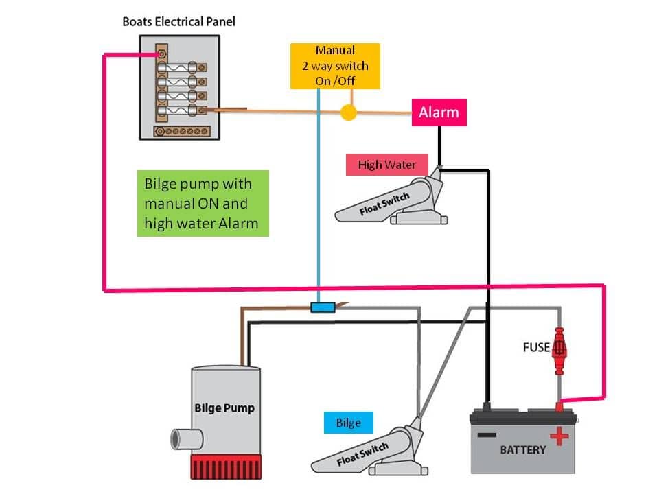
Johnson Bilge Pump | Boating Forum - iboats Boating Forums Here's a basic drawing showing how the float is wired in and operates the pump, as well as how the switch on the dash works... We use Rule pumps and float switches, the 2 leads coming off the float are gray. Yours may be brown... Thanks for the diagram, it deffinately helps. Mine does not have a float swith, just the bilge pump alone.
Johnson Pump Float Switch - YouTube About Press Copyright Contact us Creators Advertise Developers Terms Privacy Policy & Safety How YouTube works Test new features Press Copyright Contact us Creators ...
Mayfair Bilge Pump with Float wiring diagram | Boating ... I wanted to post this wiring diagram (simply drawn), for all the folks that have trouble following written directions for wiring a Mayfair Bilge Pump with Electronic Float Control. This is wired to an indash switch so it works with the manual switch and it works automatically when the switch is off. Hope you dont mind my artistry! Attachments
Mayfair Bilge Pump Wiring Diagram | Manual E-Books - Bilge ... According to previous, the traces at a Bilge Pump Float Switch Wiring Diagram represents wires. Sometimes, the cables will cross. However, it doesn't imply connection between the wires. Injunction of 2 wires is generally indicated by black dot in the junction of two lines. There will be main lines that are represented by L1, L2, L3, and so on.
















0 Response to "40 johnson bilge pump wiring diagram"
Post a Comment